Page 97 of 168

70019401960 Specifications
Section 2 B 280 Engine
Early type
Bosch No ........")
( ,
Lambda-sond
0258~ 138 112
Fuel pump
&' 0580254 ... 138069
Capacity at a line pressure of 250 kPa (36 psi)
70019401960 Specifications
Section 2 B 280 Engine
Early type
Bosch No ................ 020
Volvo PIN ............ 1 378 123-2
Resistance
of preheating resistors:
Late type
... 034
3501 753-2
cold Lambda sand (20°C = 68°F) ............... 3 n
warm Lambda sand (above 350°C = 662°F) . . .. 13 n
Tightening torque ....... ............ 55 Nm (40 ft Ib)*
* Apply Never seez (PIN 1 161 035-9) to threaded section of sond .
Type I
Bosch No ................ 948
Volvo PIN ............ 1 336 677-8
Type II
... 039
1 389449-8
+20°C (68°F) and 12 V .................................... . 140 litres/hr (37.0 US Galls. per hr)
120 litres/hr (31.7 US Galls . per hr)
95
litres/hr (25.0 US Galls. per hr)
11 V ........•............................
10V .. .................................. .
Current consumption
at a line pressure of 300 kPa (42 psi),
+20°C (68°F) and 12 V .................................... . max 5.0 A
Tank pump
Current consumption . . . . . . . . . . . . . . . . . . . . . . . . .. 3-4 A
95
'" III , II
NI' III ill ,II'
'"
)
Page 98 of 168

70019401960 Specifications
Section
2 B 280 E ngine
General
Group 26 Cooling system
Coolant -compos it ion -gua rantee
Since aluminium is used in ihe engines, active corrosion
protection
is necessary in the coolant to help prevent corro
sion damage.
Use genuine
Volvo coolant, type C (blue-green ) diluted
with clean water in proportions of 50/ 50. This mixture helps
to prevent corrosion and frost damage.
• Never top-up the cooling system with water alone. Use
genuine
Volvo coolant diluted with clean water in propor
tions of
50/50.
•
The coolant should be changed every 25,000 miles
(40,000
km) since the corrosion-protective additives in
the coolant lose their effect in time.
• Clean cooling system with solvent (P/N 1161328-8)
prior to
filling new coolant.
litres
Capacity. . . . . . . . . . . . . . . . . . . . . . . . . . . . . . . . . . . . . . . . . . . . . . . . . . . . 10.0 U S qts
10.5
Expans ion tank
Pressure valve in cap opens at:
overpressure ...................................... .. ..... .
underpressure
............................................ .
Thermostat
Marking .. .................................................. .
Starts opening at. ........................................... .
Fully open at ............................................... .
Fan belts
kPa
150
7.0
87
86-88° (187-190°F)
9l" (20l"F)
Designation, 760. . . . . . . . . . . . . . . . . . . . . . . . . . . . . . . . . . . . . . . . . . . . . HC 38 cog x 1075
780.
. . . . . . . . . . . . . . . . . . . . . . . . . . . . . . . . . . . . . . . . . . . . HC 38 cog x 1100
96
psi
21
1.0
Page 99 of 168

Group 28 Ignition system
~
~~ ~ 134864
Type ....................................................... .
EZ115K
1-6 -3-5 -2 -4
Firing
order ................................................. .
E ng in e
Ig niti on tim ing Speed rls
type b.t.d
.c. (rpm)
B280E 10° 12 .2-12 .8 (730-770)
B280 F 16° 12 .2-12.8 ( 7 30-770)
Ignit ion coil
Resistance of primary coil
(terminals
1 and 15) . . . . . . . . . . . . . . . . . . . . . . . 0.6-0.8 n
Resistance of secondary coil
(terminal
1 to HT terminal) ..... . . . . . . . . . .. 6 .9-8.5 kn
Spark plugs, glow plugs
Eng in e type Des
ig nation
B
280 E Scandinav ia , B 280 F HR6DC
B
280 E Other markets HR5DC
1317~
PIN
1 269915-3
1
389896-0
Kit num ber
273599-1
270590-3
70019401960 Specifications
Section
2 B 280 E ngine
Electrode gap . . . . . . . . . . . . . . . . . . . . . . . . . . . . . . . . . . . . . . . . . . . . . . . 0.6-0.7 mm (0.0236-0.0276 in)
Tightening torque, (unoiled plugs). . . . . . . . . . . . . . . . . . . . . . . . . . . . . . 12 Nm (9 ft Ib)
Knock sensor
14 6 805
Tightening torque. . . . . . . . . . . . . . . . . . . . . . . . . . . . . . . . . . . . . . . . . . . . 20 Nm (14.5 ft Ib)
97
III ... III II
II' ... II' ·11 II
Page 100 of 168

70019401960 Specifications
Section 2 B 6304 Engine
Section 2 B 6304 Engine
Group 20 General.... . . . . . . . . . . . . . . . . . . . . . . . . .. 98
Group 21 Engine............................... 98
Group
22 Lubricating System. . . . . . . . . . . . . . . . . . .. 101
Group 23 Fuel system . . . . . . . . . . . . . . . . . . . . . . . . .. 102
Group 26 Cooling system . . . . . . . . . . . . . . . . . . . . . .. 106
Group 28 Ignition system . . . . . . . . . . . . . . . . . . . . . . . . 107
Group 20 General
Performance , compression ratios, octane requirements
Engine Notes Compres-Octane
Output
type sion
requirement
Ratio
RON· kWat hp at Nm at
rls rim
rls
B6304F 10,71
) 95 150/100 204/6000 267172
Notes:
1) Unleaded fuel only. Can be run on 91 octane unleaded . • RON stands for Research Octane Number, and is a measure of the ability of the fuel to withstand knocking. MON stands for Motor Octane Number, another way of measuring the same property .
(R+M)/2, also called AKI (Anti Knock Index) is a combination of these two measurements . 95 RON is equivalent to 91 (R+M)/2. 91 RON is equivalent to 87 (R+M)/2 .
Other general data
Number of cylinders ......................................... .
Bore .
.................................................... .. .
Stroke .......................................... .......... . .
Displacement ......................... ................ ...... .
Firing order
............................................... .. .
Compression
(normal rating) 1) • ••••• ••••••••••••••••• •.••••••.•
Weight, approx ............................................. .
1) With hot engine, throttle wide open and starter motor cranking at 4.2-5.0 rls (250-300 rIm)
6
83.00 mm (3.268 in)
90 .00 mm (3.543 in)
2.922 dm3 (Iitres)
1-5 -3-6-2 -4
1 .3-1 .5 MPa (184-213 psi)
180 kg (397 Ib)
Group 21 Engine Block
Cylinder head
Max torque
kpm at
rim
27.214300
Height, new ............................... ........... mm (in) 129 .00±0.05
Max machining .............. ......................... mm (in) 0.3
(5.0787±0.0020)
(0.0012)
Max warp:
along ......... .... ................................. mm (in) 0.020
across .................................. ...... ..... mm (in) 0 .008
98
Page 101 of 168

........................... ....... mm (in)
(marked
D) ........... ....................... mm (in)
(marked
E) .................................. mm")
(
Cylinder block
Bore
Standard (marked C)
........................... ....... mm (in)
(marked
D) ........... ....................... mm (in)
(marked
E) .................................. mm (in)
(marked
G) ................... . .............. mm (in)
Rebore if wear exceeds 0.1 mm and oil consumption is abnormally high.
Pistons
Piston diameter
Diameter to be measured at right
angles to gudgeon pin and
16 mm from bottom of piston.
Standard (marked C)
.................................. mm (in)
(marked
D): ................................ . mm (in)
(marked
E) .. , ........................ ....... mm (in)
(marked
G) ............ ...................... mm (in)
Piston weight
.......................................... g (oz)
Max weight difference between pistons in same engine
......... g
Piston rings
Axial clearance in piston groove ............................ mm
in
Ring gap (measured in cylinder, bore 83.00 mm) ............. mm ? in
Gudgeon (P iston ) pins
Fit in connecting rod ......................................... .
in piston
................................................ .
Valve system
Hydraulic
Valves
Length inlet ...... .................................... mm (in)
exhaust
.............. ......................... mm (in)
Matching surface
angle .................................. .... 0
Edge height, new valve ................................ mm (in)
min after machining .
...................... mm (in)
Max machining of
valve stem ................ ........... mm (in)
Valve Seats
Diameter standard .................................... mm (in)
oversize
.... ................................ mm (in)
Matching surface
angle .......................... ............ 0
Reduction angle, upper ...................................... 0
lower ................. ....... .............. 0
Width ...................................... ... ...... mm (in)
70019401960 Specifications
Section 2 B 6304 Engine
83.00-83.01
83.01-83 .02
83.02-83.03
83.04-83.05
82.98--82.99
82.99--83.00
83.00-83.01
83.02 -83.03
350
± 5
10
(3.2677-3 .2681 )
(3.2681-3.2685)
(3.2685-3 .2689)
(3.2693-3.2697)
(3.2669--3.26 7
3)
(3.2673-3.2677)
(3.2677-3.
2681 )
(3.2685-3.2689)
(12.5 ±
0.2)
(0.4)
Upper
camp. rings
0.05-0.085
0.0020-0.0033
0.2-0.4
0.008--0.016
Lower
camp. rings
0.03-0.065
0.0012-0.0026
0.2-0.4
0.008--0.016
Oil scraper
ring s
0.02-0.055
0.0008 -0.0022
0.25-0.5
0.009--0 .020
Light thumb pressure (close running fit)
Thumb pressure (push fit)
104.05±0.18
103.30±0.18
45.5
1.5
1.2
0 .4 (4
.
096±0.007)
(4.067±0. 007)
(0.059)
(0.047)
(0.016)
inl et exhaust
32.61 (1.284) 28.61 (1.126)
33.11
(1.304) 29 .11 (1.146)
45.25 45.25
20.25 15.25
60.25 60.25
1.4-1.8 (0.055-0.071) 1.8--2.2 (0.071-0.087)
99
Itl
It
Itl
.... 1 '11 Itl ... Itl
Page 102 of 168

oversize 1
................................... mm (in)
oversize")
70019401960 Specifications
Section 2 B 6304 Engine
Valve Guides
Diameter standard .................................... mm (in)
oversize 1
................................... mm (in)
oversize 2
...................... ............. mm (in)
Clearance, valve stem-guide (measured with new valve) ... mm (in)
Min .
................................................ mm (in)
Valve Springs
External diameter ..................................... mm (in)
Internal diameter ...................................... mm (in)
Length at
270 ± 15 N ................................. mm (in)
Length at
670 ± 32 N ................................. mm (in)
Timing gear
Cams haft
Marking
Inlet ..................................................... .
Exhaust
.................................................. .
Max
lift height ................... ..................... mm (in)
Axial clearance ....................................... mm (in)
Crankshaft assembly
Crankshaft
Max out-ol-true ...................................... . mm (in)
Axial clearance ....................................... mm (in)
Radial clearance (main bearings) ....................... mm (in)
Main bearing journals
Diameter ............................................ mm (in)
Out-ol-round, max
.................................... mm (in)
Connecting rod bearing journ als
Diameter ................................... ......... mm (in)
Out-aI-round, max
.................................... mm (in)
Connecting rods
Axial clearance at crankshaft ........................... mm (in)
Tightening torques
Tightening torques apply to oiled nuts and bolts. Degreased
(washed) parts must
be oiled prior to assembly.
Cylinder
head (stage 1) .............................. Nm (ft Ib)
(stage 2) .............................. Nm (ft Ib)
(stage 3) angle -tightening ....................... 0
Bolts should be tightened in sequence Irom center towards ends .. .
Middle section M 10 (stage 1) ........................ Nm (ft Ib)
M 10 (stage 2) ........................ Nm (ft Ib)
M 8 (stage 3) ........................ Nm (It Ib)
M 7 (stage 4) ........................ Nm (It Ib)
M 10 (stage 5) angle -tightening ................. 0
Bolts should be tightened in sequence Irom center towards ends.
100
inlet
12.00 (0.4724)
12.1 (0.4764)
12.2 (0.4803)
0.06 (0.0024)
0.03 (0.0012)
27.90±0.20
20.10±0.20
34.00
24.50
PC I
PC E
9.00 0.05-0.20
0.004
0.08-0.19
0.024-0.047
65.00 0.004
50.00 0.004
0.15-0.45
20
60 150
20±2
45±4
24±4
17±3
90
exhaust
12.00 (0.4724)
12.1 (0.4764)
12.2 (0.4803)
0.06 (0.0024)
0.03 (0.0012)
(1.098±0.008)
(0.791 ±0.008)
(1.339)
(0.965)
(0.354)
(0.002-0.008)
(0. 00016)
(0.003-0.0075)
(0.00094-0.0019)
(2.559)
(0.00016)
(1.969)
(0.00016)
(0.0059-0 .0177)
(15)
(44)
(15±1.5)
(33±3)
(18±3)
(12±2)
Page 103 of 168
 ................ Nm (ft Ib)
(stage 2) angle-tightening ......... 0
Crankshaft pulley (vibration damper), center bolt ........ Nm (ft Ib)
Flange bolts, vibr")
(
Connecting rod bearing caps (stage 1) ................ Nm (ft Ib)
(stage 2) angle-tightening ......... 0
Crankshaft pulley (vibration damper), center bolt ........ Nm (ft Ib)
Flange bolts, vibration damper (stage 1) ............... Nm (ft Ib)
(stage 2) angle-tightening ........ 0
Driver plate (stage 1) ......................... ....... Nm (ft Ib)
(stage 2) angle-tightening ......................... 0
Camshaft wheel. .................................... Nm (ft Ib)
Tensi oning pulley, camshaft timing belt ................ Nm (ft Ib)
Damper unit, camshaft timing belt ..................... Nm (ft Ib)
Angle pulley, camshaft timing belt ..................... Nm (ft Ib)
Water pump ........................................ Nm (ft Ib)
Pin bolts, exhaust manifold (in cylinder head) ........... Nm (ft Ib)
(to front pipe) .............. Nm (ft Ib)
Oil sump pan ....................................... Nm (ft Ib)
Plug, oil sump ...................................... Nm (ft Ib)
Oil suction line ...................................... Nm (ft Ib)
Oil cooler, connector block ........................... Nm (ft Ib)
Oil trap ............................................ Nm (ft Ib)
Nipple, oil·filter ...................................... Nm (ft Ib)
Oil pressure switch .................................. Nrn (ft Ib)
Impulse sensor ..................................... ~~m (ft Ib)
Knock sensor ....................................... Nm (ft Ib)
Temperature sensor, rear edge of top cover ............ Nm (ft Ib)
Temperature sensor, thermostat ............... ....... Nm (ft Ib)
Plug, O-adjustment tool .............................. Nm (ft Ib)
Spark plugs ... ..................................... Nm (ft Ib)
20
90
300±30
35
60 45
50
20±2
39±5
24±4
24±6
17±3
20±3
35±5
17±3
38±5
17±3
17±3
15±2.5
40±2
40±5
8±2
20±2
20±2
10±2.5
38±6
25
Group 22 Lubricating System
Genera l
Oil fill volume and type, see p. 12.
Oil pressure with warm engine and new oil filter :
at 12,5 rls (750 rim), at least ....... ................ Mpa (psi) 0.1
at
50 rls (3 000 rim), at least ....................... Mpa (psi) 0.3
max
...................... ....................... Mpa (psi) 0.5
Lubricat ing oil pump
Relief valve spring, length under various loads
unloaded
.................... ....... mm (in)
loaded to 52±4 N (5.2 kp) ....... .... mm (in)
loaded to 85±8 N (8.5 kp) ........... mm (in)
82.13
56.1
39.9
70019401960 Specifications
Section 2 B 6304 Engine
(15)
(221 ±22)
(26)
(33)
(15±1.5)
(29±4)
(18±3)
(18±4)
(13±2)
(15±2)
(26±4)
(13±2)
(28±4)
(13±2)
(13±2)
(11 ±2)
(29±1.5)
(29±4)
(6±1.5)
(15±1.5)
(15±1.5)
(7±2)
(28±4)
(18)
(14)
(43)
(71 )
(3.233) (2.21)
(1.57)
101
I ..... ' '.','
"' ,III III ill u,1
Page 104 of 168
 Idli")
70019401960 Specifications ./ " ' "."--Section 2 B 6304 Engine
Group 23 Fuel System
CO content , idle speed
Check values for CO content. ............................... % 0.4-0.8
12.5 (750) Idling speed ............................ ......... .... rls (rim)
CO content and idling speed can not be adjusted , only checked. Shift
selector
to be in position P when checking.
150362
o 280 160 ... 145 789
t o 280 150 ...
145677
102
Motronic 1.8
Control unit
Bosch number ....................... . 0261 200362
Volvo part number. . . . . . . . . . . . . . . . . . . . . . . 3 517 623-9
Air mass meter
Bosch number ...................... " 0 280 213 012
Volvo part number ....................... 3517569-4
Resistance:
between
terminals 2 and 3. . . . . . . . . . . . . . . .. 2.5-4 0
Pressure regulator
Early type
Bosch number . . . . . . . . . . . . . . . . . . . . . .
.. 0 280 160 294
Volvo part number. . . . . . . . . . . . . . . . . . . . . .. 3 517 064-6
Line pressure ..................... " 300 kPa (4 3 psi)
Late type
Bosch number . . . . . . . . . . . . . . . . . . . . . . ..
0 280 160 731
Volvo part number ..................... .. . 3547653
Injector
Bosch number . . . . . . . . . . . . . . . . . . . . . . .. 0 280 150 762
Volvo part number ....................... 3517572-8
Injected quantity . . . . . . . . . . . . . . . . . . . . . .. 185 cm3/min
at line pressure .................. ... 300 kPa (43 psi)
 1
1 2
2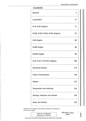 3
3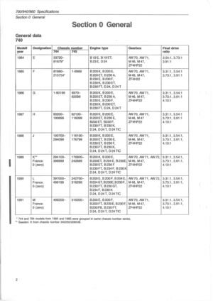 4
4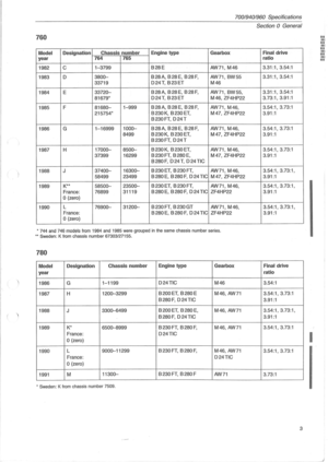 5
5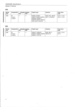 6
6 7
7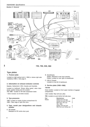 8
8 9
9 10
10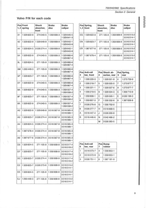 11
11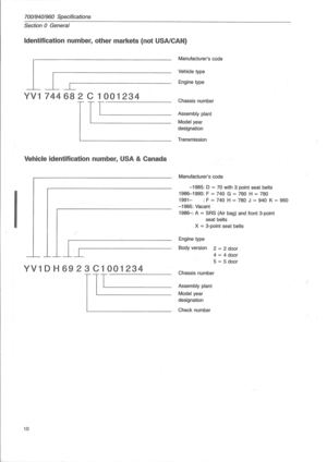 12
12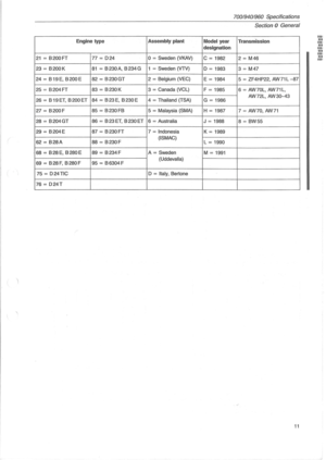 13
13 14
14 15
15 16
16 17
17 18
18 19
19 20
20 21
21 22
22 23
23 24
24 25
25 26
26 27
27 28
28 29
29 30
30 31
31 32
32 33
33 34
34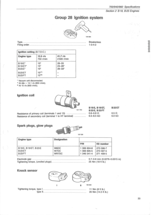 35
35 36
36 37
37 38
38 39
39 40
40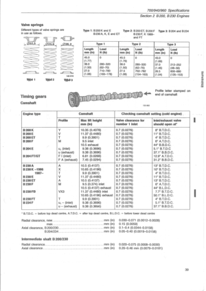 41
41 42
42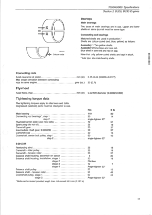 43
43 44
44 45
45 46
46 47
47 48
48 49
49 50
50 51
51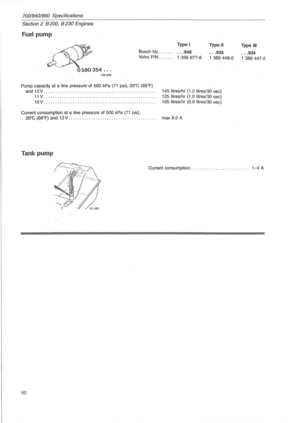 52
52 53
53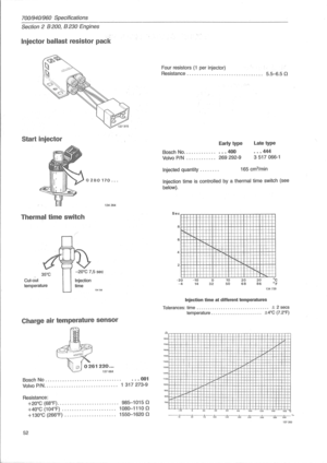 54
54 55
55 56
56 57
57 58
58 59
59 60
60 61
61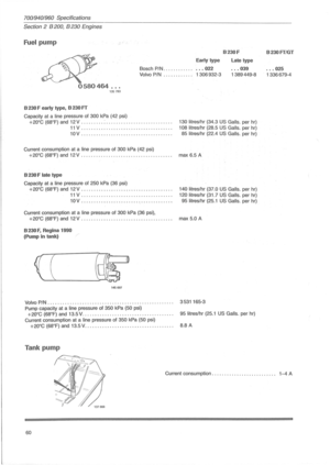 62
62 63
63 64
64 65
65 66
66 67
67 68
68 69
69 70
70 71
71 72
72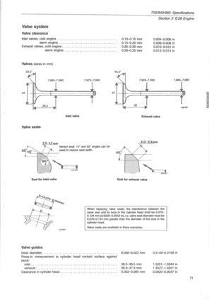 73
73 74
74 75
75 76
76 77
77 78
78 79
79 80
80 81
81 82
82 83
83 84
84 85
85 86
86 87
87 88
88 89
89 90
90 91
91 92
92 93
93 94
94 95
95 96
96 97
97 98
98 99
99 100
100 101
101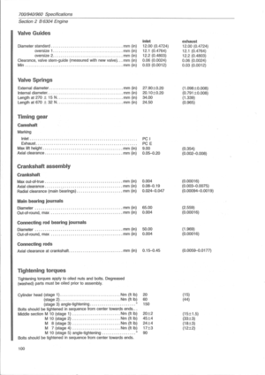 102
102 103
103 104
104 105
105 106
106 107
107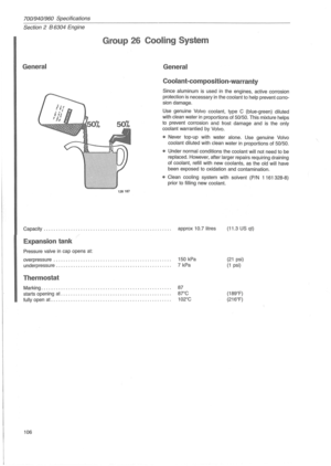 108
108 109
109 110
110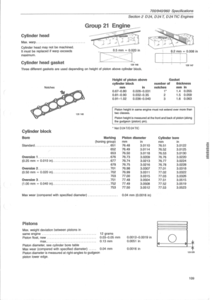 111
111 112
112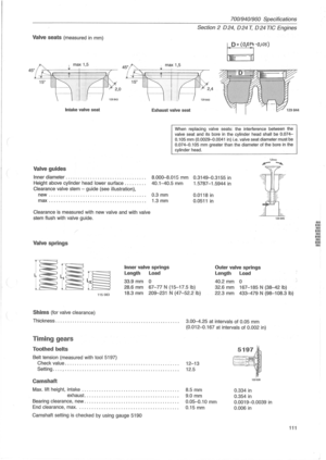 113
113 114
114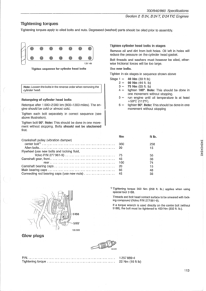 115
115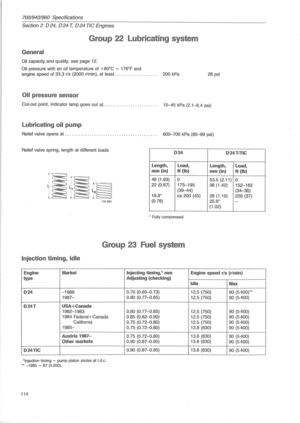 116
116 117
117 118
118 119
119 120
120 121
121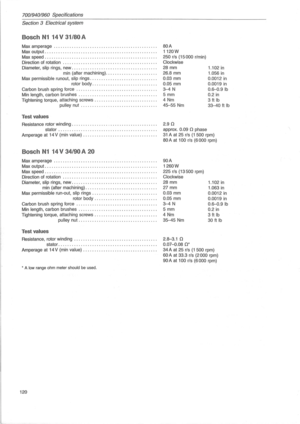 122
122 123
123 124
124 125
125 126
126 127
127 128
128 129
129 130
130 131
131 132
132 133
133 134
134 135
135 136
136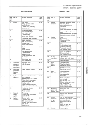 137
137 138
138 139
139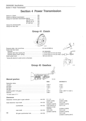 140
140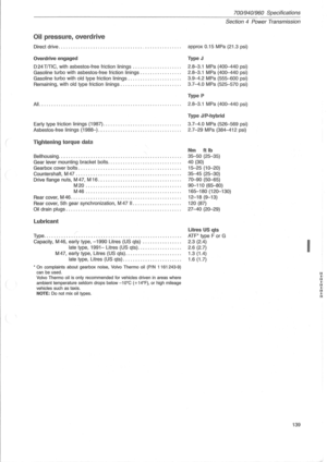 141
141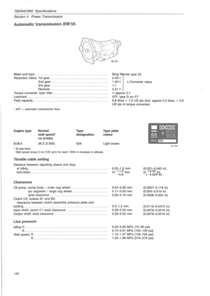 142
142 143
143 144
144 145
145 146
146 147
147 148
148 149
149 150
150 151
151 152
152 153
153 154
154 155
155 156
156 157
157 158
158 159
159 160
160 161
161 162
162 163
163 164
164 165
165 166
166 167
167