Page 17 of 168

70019401960 Specifications
Section 2 B 19, B 23 Engines
Section 2 B 19, B 23 Engines
Group 20 General ................................ 15
Group
21 Engine assembly ........................ 16
Group 22 Lubricating system
....................... 20
Group 23 Fuel system ............................ 21
Group 25 Intake and exhaust systems .............. 31
Group 26 Cooling system .......................... 32
Group 28
Ignition system .......................... 33
j'"
I.t
Group 20 General ~ :,
129750
Performance , compression ratios, octane requirements
Engine Remarks Compres-Octane
Output Max torque
type sion
ratio r
equire-
ment
kWat hp at
r/s r/min
819E 10.0:1 98 86/100
117/6000
819ET 7.5:1 98 110/92
150/5500
823E Scandinavia, Switzerland 10.3:1 96 95/88 129/5250
Other markets 10.0:1 98 96/90 131/5400
823ET 9.0:1 981 127/95 173/5700
823FT 8.7:1 912
• 3 117/88 160/5300
1575/5300
1) Australia 97-98 octane 2) Unleaded
petrol (gasoline) 91 octane RON (Research Octane Number). AKI = 87, according to R+2M where M stands for Motor Octane Number
. "
Nm at
r/s
158/50
230/60 190/50
190/60
250/57
250148
3) Fill with premium unleaded petrol (gasoline) (AKI = 91) to improve performance and driveability at altitudes in excess of 2000 It (600 m) in warm climates 4) Ft Ib 5) Horse power.
Other general data
No. of cylinders ............................................. .
Bore .
............................................. .. mm (in)
Stroke ..
.... ......................................... mm (in)
Displacement. ...................................... dm3 (litre)
Firing order ................................................. .
Compression pressure1) ..
............................ MPa (psi)
Max . deviation between
cylinders ................... MPa (psi)
Approx. weight.
............... ........... ..... ......... kg (Ib)
Turbocharged versions ................................. kg (Ib)
1) With hot engine, throttle wide open and starter motor cranking at 4.2-5.0 rls (250-300 r/min).
819
4
88.9
(3.503)
80 (3.152)
1.99
1-3-4-2
0.9 (128)
0 .2 (28)
165 (363)
170 (375)
823
4
96 (3.782)
80 (3.152)
2.32 1-3-4-2
0 .9 (128)
0 .2 (28)
165 (363)
170 (375)
kpm at
r/min
16.1/3000
23.4/3600
19.4/3000
19.4/3600
25.5/3400
25.5/2900 184
4/2900
15
Page 18 of 168
 146.1 (5.756)
min (after machining)
......")
70019401960 Specifications
Section 2 B 19, 823 Engines
Group 21 Engine block
Cylinder head
Height, new ................................... mm (in) 146.1 (5.756)
min (after machining)
.................... mm (in) 145.6 (5.737)
Max warp ..
.. ..................................... . .
NOTE: If warp is greater than 1 .0 mm (0.094 in) lengthwise
or 0 .5 mm (0.097 in) crosswise, cylinder head must be re
placed.
Cylinder block
Bore 819 823
Standard C ............................................ .. mm
(in)
D .............................................. mm (in)
E .............................................. mm
(in)
G ........................................... . .. mm
(in)
Oversize 1
...................................... .... .... mm
(in)
2 ..... . -:-......................... ....... ....... mm
(in) 88.9D-88
.
91
(3.5027-3 .5031 )
88 .
91-88.92
(3.5031-3.5034)
88.92 -88.93
(3.5034-3.5038)
88.94-88.95
(3.5042-3.5047)
89 .29-89.30
(3.518D-3 .5184)
89.67-89.68
(3. 533D-3 .5334)
96 .0D-96.01
(3.7824-3. 7828)
96 .01-96.02
(3.7828-3.7832)
96 .02-96.03
(3.7832-3.7836)
96 .04-96.05
(3.7 84D-3 .7844)
96.3
(3.7 942)
96 .6
(3.8060)
Rebore if wear exceeds 0.1 mm (0.004 in) and oil consumption is very high.
Pistons
A = Overall height
8
= From gudgeon (piston) pin to crown
C = Diameter to be measured at right angles to gudgeon pin at
distance
C from bottom of piston.
Engine Weight in gms1 (oz) Dimension mm (in)
type A 8
8 19 E
515±6 (18.4±0.2)
73.9 (2.912) 46.7 (1.840)
8 19
ET 510±6 (18.2±0.2) 71.0 (2.797) 46.0 (1.812)
823E 570±7 (20.4±0.3) 76.4 (3.010) 46.4 (1.828)
823ET 562±7 (19.8 ±0.3) 8.4 (2.657)
46.4 (1.828)
823FT 562±7 (19.8±0.3) 8.7 (2.657)
46.7 (1.840)
1) Max weight difference in same engine = 12 gms (0.43 oz)
Piston running clearance
819 E, 823 E ........................................ mm (in)
819ET .............................................. mm (in)
823 ET, 823 FT ...................................... mm (in)
16
C
7 (0.276)
7 (0.276)
8 (0.315)
12 (0.423)
12 (0.423)
0.01- 0 .04 (0.0004-0.0016)
0 .03- 0.06 (0.0012-0 .0024)
0 .05-0.07 (0.002D-0 .0028)
J
ma x o 25mm
129826
137551
Page 19 of 168

(
70019401960 Specifications
Section
2 B 19, B 23 Engines
P iston rings
129521
Clearance In piston groove
Clearance in piston groove
819 E, 819 ET, 823 E .................................. mm
(in)
823ET, 823FT .............. .......................... mm
(in)
Ring gap (see above)
819E, 819ET, 823E .................................. mm
(in)
823ET, 823FT ................ .......... .............. mm
Gudgeon (Piston ) pins
Fit, in connecting rod. . . . . .. Light thumb pressure
(close running fit)
in piston. . . . . . . . . . . . . .. Thumb pressure (push fit)
Valves
Valve clearance
Inlet
and exhaust valves
(in)
cold engine ............................................ mm
(in) warm engine ........................................... mm
(in)
Adjusting shim, thickness .................................. mm
(in)
Valves
Upper
Camp.
rings
0.040-0 .072
(0. 0016-0.0028)
0.060-0 .092
(0.0024-0.0036)
0 .35-0.65
(0.0014 -0 .0026)
0.40-0 .
65
(0.0158-0.0256)
Checking
0.30-0.40
(0.012-0.Q16)
0.35-0.45
(0.014-0.018)
3 .
30-4.50
Ring gap 129 520
Lower Oil scraper
Camp.
rings rings
0.040-0.072 0.030-0.062
(0.0016 -0 .0028) (0.0012 -0.0024)
0.040-0.072 0.030-0.065
(0.0016-0.0028) (0.0018-0.0026)
0.35-0.55 0.25-0.60
(0.0014-0.0022) (0.0010-0.0024)
0.40-0.65 0.30-0.60
(0.0016-0.0256) (0.0118-0.0236)
'Adjusting
0.35-0.40
(0. 014-0 .016)
0.40-0.45
(0. 016-0.018)
(0.1300-0 .1773)
in increments of
0.05 (0.002)
IMPORTANT: Valves are stellite-flashed and must not be machined . They may only be ground in against seat. IMPORTANT! Scrapping valves. Exhaust valves in turbo engines are sodium filled and must not be mixed with ordinary
scrap iron without first removing the sodium.
Min: 7,935
Inlet valve
44,5°
44,5 °
Min: 7,945
144027
Exhaust valve turbo engines (8 19 ET, 823 ET/FT)
Exhaust valve E-engines (8 19 E, 823 E)
17
III' III III
III
III ,111 III ·111 III
Page 20 of 168

70019401960 Specifications
Section 2 B 19, B 23 Engines
Valve seat
Inlet
Valve guides
Exhaust
D+O,17mm
~\ i~
133646 113945
When replacing valve seats the interference between the seat
and its bore should be 0.17 mm (0.0067 in) i. e . valve seat diameter should be 0.17 mm greater than the diameter of bore in cylinder head.
Inner diameter ........... . ..... ...... ....... ............. mm
Inlet valve
8.000-8.022 mm
(0.3152-0.3161 )
15.4-15.6
(0.6068-0.6146)
Exhaust valve
8.000-8. 022
(0.3152-0.3161 )
17 .
9-18.1
(0.7053-0.7131 )
(in)
Height above upper face of cylinder head ................... mm
(in)
Clearance , valve stem-guide (measured with new valve) ,
new .......... . ...................................... . mm
(in)
max .
................. ................ . ~ .. ,,~ ....... "" ....... mm
(in)
Valve guides are available in three oversizes, marked
with grooves .
0.030-0.060
(0.0012-0.0021
)
0 .15
(0.0059)
Marking
0.060-0.090
(0.0024-0.0035)
0.15
(0.0059)
Reamer for seat
Standard
No groove
V alv e springs mm (in)
~
I. 032,5 . 1
rn~
Typ e 1
113946
wu , .. 025,9 1 I •
..g======'lb
Type 2 135065
Adjusting shim s mm (in)
Oversize 1
1 groove 5161
Oversize 2 2 grooves 5162
Oversize 3 3 grooves 5163
NOTE! The force used when pressing in valve guides must be at least 9000 N (1980 Ib). If the pressing force used is lower
then the recess for the guide must be reamed out to the nearest oversize and a guide of the corresponding size pressed in.
B 19 E, B 23 E, B 23 ET
B 19 ET, B 23 FT
Type 1 Type 2
Length Load
Le
ngth Load
mm (in)
N (Ib) mm (in)
N (Ib)
45.0 0 45.5 0
(1.77)
(1.79)
38.0
280-320 38.0 280-320 (1.50) (62-70)
(1.50) (62-70)
27 .0
710-790 27 .5 702-782
(1.06)
(156-174)
(1.08) (154-172)
Thickness.
. . . . . . . . . . . . . . . . . . . . . . . . . . . . . . . . . . . . . . . . . . . . . . . . . . 3 .30-4.50 (in increments of 0.05) (0. 1300-0.1773) (in increments of 0.0020)
18
Page 21 of 168

Marking Max
lift height")
(
70019401960 Specifications
Section 2 B 19, B 23 Engines
Timin g gears
Camshaft Letter stamped on
end ot camshaft
Engine type Camshaft
Check valves (cold engine)
Marking Max
lift height mm (in) Valve clearance
No.1 intake
valve mm (in)
B
19E A 10.5 (0.4137) 0.7 (0.0276)
B19ET T 9.9 (0.3901)
0.7 (0.0276)
B23E A 10.5 (0.4137) 0.7 (0.0276)
B23ET B 10.6 (0.4176) 0.7 (0.0276)
B23FT T 9.9 (0.3901)
0.7 (0.0276)
Radial clearance
............................................ 0.030-0 .071
max... . .... ... ............................... 0.15
Axial clearance . . . . . . . . . . . . . . . . . . . . . . . . . . . . . . . . . . . . . . . . . . . . . . 0.1-0.4
Int ermed iate shaft
Intake valve should
open at
13° B.T.D.C
4° B.T.D.C
13° B.TD.C
19° B.TD.C
4° B.iD.C
(0.0012-0 .0028)
(0.0012-0.0028)
(0.0344-0.0158)
Radial clearance.
. . . . . . . . . . . . . . . . . . . . . . . . . . . . . . . . . . . . . . . . . . . . 0.020-0.075 (0.0008-0.0030)
Axial clearance .
. . . . . . . . . . . . . . . . . . . . . . . . . . . . . . . . . . . . . . . . . . . . . 0.20-0.46 (0.0079-0.0181)
Crankshaft assembly
Crankshaft
Max out-ot-true .............................. mm (in)
Axial clearance, max ......................... mm (in)
Radial clearance (main bearings) .............. mm (in)
Connecting
rod bearings,
axial clearance ............................. mm (in)
radial clearance ............................ mm (in)
Main bearing journals
Out-oft-round, max ........................... mm (in)
Taper, max
.................................. mm (in)
Diameter, Standard .
.......................... mm (in)
undersize 1
........................ mm (in)
2 .
................ ....... mm (in)
Connecting rod bear ing journ als
Out-ot- round max ............................ mm (in)
Taper, max
.................................. mm (in)
Diameter, standard
........................... mm (in)
undersize 1
........................ mm (in)
2 ........................ mm (in)
Connecting rods
0.05 (0.0020)
0.25 (0.098)
0 :028-0.083 (0.0011-0.0033)
0.15-0.35 (0.0059-0.0138)
0 .024-0.070 (0.0009-0.0028)
0.07 (0.0028)
0.05 (0.0020)
63.451-63.464 (2.5000-2.5005)
63.197-63.210 (2.4900-2.4905)
62.943-62.956 (2.4800-2.4805)
0.05 (0.020)
0.05 (0.020)
53.987-54.000
(2.1271-2.1276)
53.733-53.746 (2.1171-2.1176)
53.479-53.492
(2.1071-2.1076)
Axial clearance
at crankshaft .................. mm (in) 0.15-0.35 (0.0059-0.0138)
Max weight deviation between connecting rods
in same engine 10 gms
Flywheel
Axial throw, max ............................. mm (in) 0.02 mm/100 mm
(0.0008/3.94 in diameter)
Taper
Out-of-round
19
1111 :111
111/ III III '
, III
III '
·111 III
"1
I
~J
Page 22 of 168
 parts must be oiled prior to assembly.
Main bearings ..........")
70019401960 Specifications
Section 2 B
19, B 23 Engines
Tightening torques
Apply to oiled nuts and bolts.
Oegreased (washed) parts must be oiled prior to assembly.
Main bearings ....................... ' ....................... .
Connecting rod bearings,
old bolts ............................ .
new
bolts ......... .................. .
Flywheel (use new bolts) ..................................... .
Spark
plugs (unoiled) .............. ; ......................... .
Camshaft sprocket
............... ........................... .
Intermediate shaft sprocket ................................. .. .
Camshaft bearing caps .
............................ ......... .
Crankshaft center
bolt ....................................... .
Cylinder head , tighten in stages:
134266
Bolts should be replaced if center section shows signs of extension. Do not re-use bolts more than 5 times . If in doubt, fit
new bolts.
Nm
110
63
70
70
25±5
50
50 20
165
1 = 20 Nm (14 ft Ib)
2 = 60 Nm (43 ft Ib)
ft Ib
80
46
51
51
18±3.5
36
36 15
120
3 = Angle-tighten 900 in one motion
'7--3---
o 0
000
8-4-2-
--9
o
115326
Tightening sequence for cylinder head bolts
Group 22 Lubricating system
General
Oil capacity and quality, see page 12.
Oil pressure at 33 rls (2,000 r/min) with warm engine
and new
oil filter ...... .............................. MPa (psi) 0.25-0.60 (35-85)
Oil pump
Axial clearance .................. ..................... mm (in)
Radial clearance (excluding bearing clearance) .......... mm (in)
Backlash (excluding bearing clearance) ................. mm (in)
Bearing clearance, drive shaft
.......................... mm (in)
idling shaft ..... ........... .......... mm (in)
Relief valve spring length under different loads
~~~ 115083
20
Lengths
39.2 mm (1.5445 in)
26.25 mm (1.0343) in)
21.0 mm (0.8274 in)
0.02-0.12
0.02-0.09
0.15-0.35
0.032-0.070
0.014-0.043
Load
o
(0.0008-0 .0047)
(0.0008-0.0035)
(0.0059-0.0138)
(0.0013-0. 028)
(0.0006-0.0017)
46-54 N (10.1-11.9 Ib)
62 -78 N (13.6-17.2 Ib)
(
Page 23 of 168
 when checking/adjustin")
(
70019401960 Specifications
Section 2 B 19, B 23 Engines
Group 23 Fuel system
CO-content , idle speed
• Selector lever must be in position P (and handbrake applied) when checking/adjusting CO or
idle speed
• CO should be checked/adjusted when engine is warm and idling
• CO
content outside check values shown below = adjust to specified setting value
• CO
content within check values need not be adjusted provided engine is operating satisfactorily
Engine Rem ar ks CO co ntent Id le spee d
type r/s (r/m in)
CO m ete r % Volv o
Adjusting Mono tes te r
(checking)
8 19E 1.0 (0.5-2.0) -15 .0 (900)
819ET 2.0 (1.0--3.0) -15.0 (900)
823E 1.0 (0.5-2.0) 1 -15 .0 (900)
823ET 1.5 (1.0--2 .5) -14.2 (850)
823FT USA + Canada 0.6 (0.4-0
.8f 20--70°3 12.5 (75W
Japan 0.6
(0.4-0.8)2 20--70°3 15.0 (900)
I) Pulsai r system disconnected and plugged. 2) Lambda-sond disconnected. 3) Lambda -sond connected . 4) AC switched off. Engine speed increases to 15.0 rls (900 r/min) when AC is reconnected.
Page CI system (819 ElE T, 823 E ). . . . . . . . . . . . . . . . . .. 22
Motronic
(823 ET) ... ......................... 25
LH -Jetronic
(823 FT) . . . . . . . . . . . . . . . . . . . . . . . . .. 28
. ~
135528
21
III IN III
III III
III III
III
J
Page 24 of 168
.spe(jifiJjations
Section 2 819, 823 Engines
CI system (B 19 E, B 19 El, B 23 E)
Pressures B19ET
Line pressure ....................................... kPa (psi)
B19E, B23 E")
700/919!~o,(}).spe(jifiJjations
Section 2 819, 823 Engines
CI system (B 19 E, B 19 El, B 23 E)
Pressures B19ET
Line pressure ....................................... kPa (psi)
B19E, B23 E
450-530 (64-75)
150-240 (21-34)
520-580 (74-82)
240-320 (34-46) Rest pressure ................................ ....... kPa (psi)
Control pressure
warm engine ...................................... kPa (psi)
345-375 (49-53)
345-375 (49-53)
295-325 (42-46)
warm engine and charge pressure of
45 kPa (6.4 psi) ................................... kPa (psi)
cold engine (see diagram)
Control pressure regulator
0438140 ...
Injector s
22
"" ' n
0437502 ... 132945
2.5 250
2.0 200
1 .5 150
1.0 100
0.5 50
o 10 20 30 40 50 60 70 80 D C 32 50 68 66 104 122 140 158 176 e F 132943·2
Type of control pressure regulator fitted to vehicles de
pends
on engine type. Identification number (last three
digits
of part number) is stamped on top of regulator .
Bosch number
B 19 E,
B23E ...... 004
B19ET ............ 117
Volvo PIN
463971-2
1 336
077-1
Resistance . . . . . . . . . . . . . . . . . . . . . . . . . . . . . . .. 20-30 (1
Type of injector fitted to engine depends on engine type.
Identification number (last three digits of part number) is
stamped on side of injector .
Bosc h number
B 19 E,
B23E ...... 015
B 19 ET ............ 020 Volvo
PIN
1
276037-7
1 306499-9
Opening pressure
......... kPa (psi) 350-410 (50-58)
No leakage permissible
below
.............. ...... kPa (psi) 290 (41)
 1
1 2
2 3
3 4
4 5
5 6
6 7
7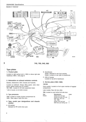 8
8 9
9 10
10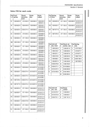 11
11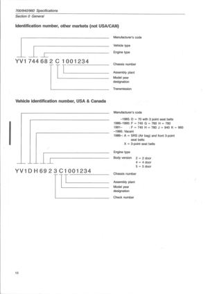 12
12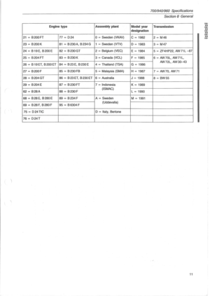 13
13 14
14 15
15 16
16 17
17 18
18 19
19 20
20 21
21 22
22 23
23 24
24 25
25 26
26 27
27 28
28 29
29 30
30 31
31 32
32 33
33 34
34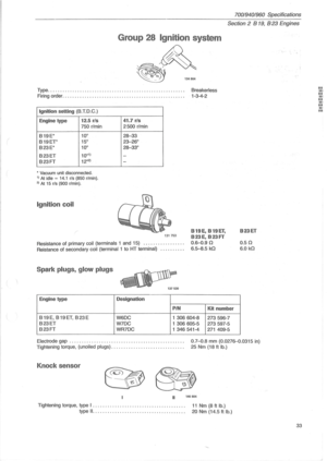 35
35 36
36 37
37 38
38 39
39 40
40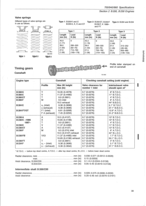 41
41 42
42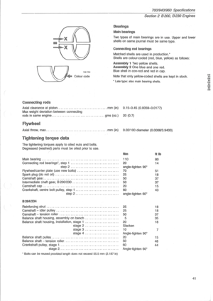 43
43 44
44 45
45 46
46 47
47 48
48 49
49 50
50 51
51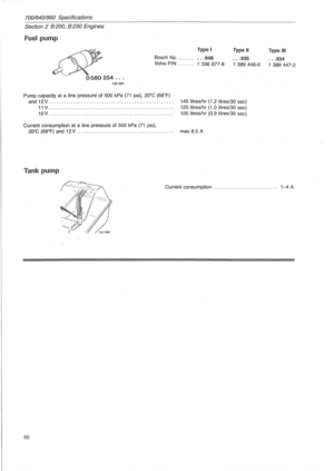 52
52 53
53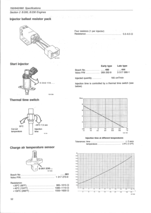 54
54 55
55 56
56 57
57 58
58 59
59 60
60 61
61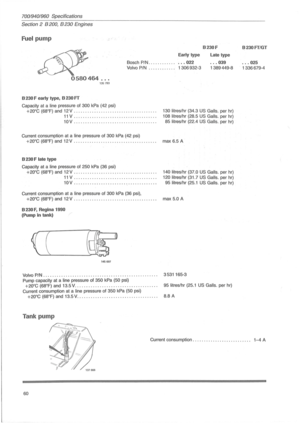 62
62 63
63 64
64 65
65 66
66 67
67 68
68 69
69 70
70 71
71 72
72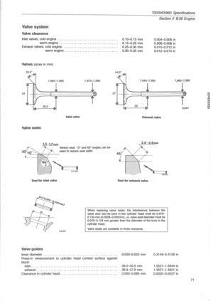 73
73 74
74 75
75 76
76 77
77 78
78 79
79 80
80 81
81 82
82 83
83 84
84 85
85 86
86 87
87 88
88 89
89 90
90 91
91 92
92 93
93 94
94 95
95 96
96 97
97 98
98 99
99 100
100 101
101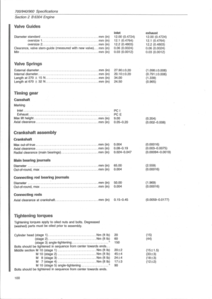 102
102 103
103 104
104 105
105 106
106 107
107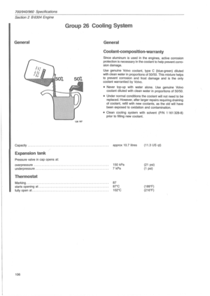 108
108 109
109 110
110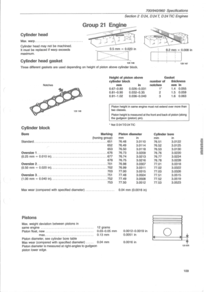 111
111 112
112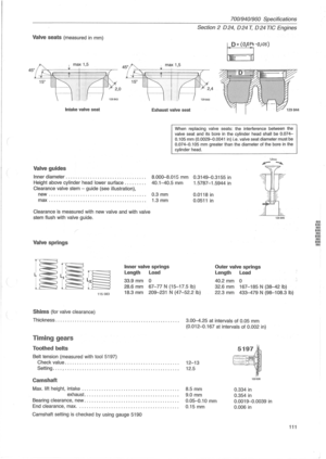 113
113 114
114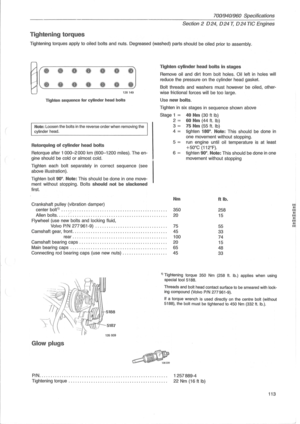 115
115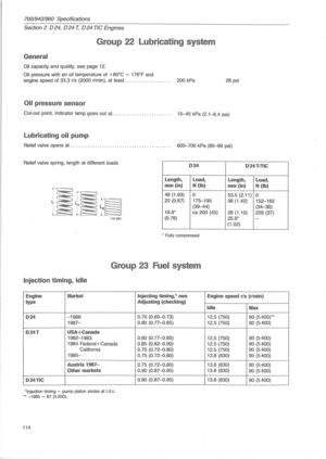 116
116 117
117 118
118 119
119 120
120 121
121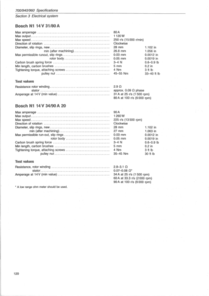 122
122 123
123 124
124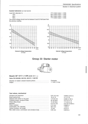 125
125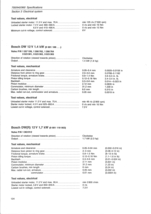 126
126 127
127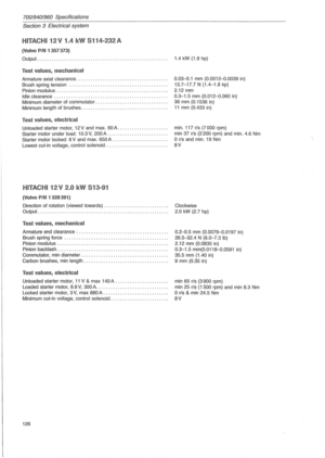 128
128 129
129 130
130 131
131 132
132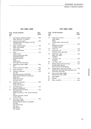 133
133 134
134 135
135 136
136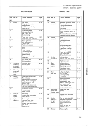 137
137 138
138 139
139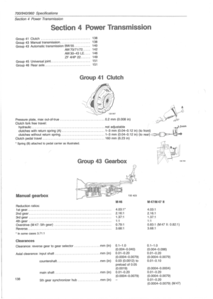 140
140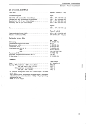 141
141 142
142 143
143 144
144 145
145 146
146 147
147 148
148 149
149 150
150 151
151 152
152 153
153 154
154 155
155 156
156 157
157 158
158 159
159 160
160 161
161 162
162 163
163 164
164 165
165 166
166 167
167