Page 137 of 168

740/940 1991
Fuse Fed
by Circuits
protected Fuse Fuse
num- rating num-
ber ber
1
Battery + Fuel pump 25 A 13 Relay, injection
system Ignition system
Lambda-sond preheating
(not B
230 FT) f-----2 Hazard flash
lights 25 A
Main beam flash (via
fuse 17 and 18)
Central locking f-----
( 3 Power seats (motors) 15 A (X-relay, main beam , not fused) 14
r----4 Brake lighi switch
15 A Bulb failure warning
- brake lights f-----15 P-shift lock, solenoid f-----5 Clock 15 A
Radio
Power antenna -Door warning lights 16
Courtesy lights Make-up mirror Glove compartment light Trunk light 17 f-----6 ECC,
heater fan 30 A
-
ECC, controll unit 18
7 30-busbar
Fog
lights (940) 30 A 19
(battery+ ) Rear fog lights or X-relay, main beam -20
8 Main relay, Power windows
(motors) 30 A
power and
heating,
21
seats
9
Ignition Fasten seat belt reminder 15 A
switch 15 I Turn indicators
Magnetic clutch, ECC comp o
-
22
Relay, electric cooling fan Main relay, power and
heating, seats
P-shift inhibitor (solenoid) (ABS surge protector not fused) I----(
10 Heated rear window 30 A
Heated mirrors 23
Power sun
roof
11 Relay , in- Tank pump
15 A
jection Lambda-sond,
pre-heating 24
system (not
B
230 FT)
12
Ignition Back-up lights 15 A 25
switch 15 Overdrive relay, M
46 Bulb failure warning
Exhaust temp. warn. (Japan)
OD, AW71
Cruise control
26
Fed by
Ignition switch 15
Ignition
switch X
X-relay, main beam
Bulb
failure
warning
Main
light relay
Main relay, power and
heating, seats
Ignition switch 15 I or light switch
Battery +
70019401960 Specifications
Section 3 Electrical System
740/940 199 1
Circuits protected Fuse
rating
Automatic preheating, diesel 15 A Fuel valve, diesel Charge pressure limiter turbo diesel EGR, diesel (Control unit, fuel system, not fused) (Control unit, ignition system, not
fused)
(Power stage , fuel system, not fused)
(Diagnostic connector, not fused)
Radio 15
A Power mirrors
Tailgate wash/wipe
Cigar
lighter
Horn 25
A Windshield wash/wipe Headlight wash/wipe Power seats (controls) (SRS Airbag not fused)
Heater fan (not ECC) 30 A
ECC , control unit
ECC, solenoid valves
Left main beam 15
A Indicator light, main beam
Right main beam 15
A
Left dipped beam 15
A
Relay, front foglight Beam length control
Right dipped beam 15
A
Beam length control
Left parking lights, 15 A
front and rear
Licence
plate light
Panel lights
Right parking lights, 15 A
front and rear
Relay, foglight front Belt and ashtray lights back
Shift selector light Lights, switches and
compartment on tunnel
Heated front seat 25
A
(power)
Reserve
(SRS diagnosis
socket)
Rear
fog lights USA/CDN 15 A
Automatic dipped beam EU/OS (can be turned off)
Radio, USA/CDN/GB
(lights) (Switch, fog lights, 940 USNCDN not fused)
Radio, amplifier 15 A
135
I
Itl Itll
,It I Iltl ·ltl 1111 III
'", II.
Page 138 of 168

70019401960 Specifications
Section
3 E lectrical System
I
960 1991
Fuse Fed by C ircuit s protecte d Fuse
960 1991
Fuse Fed by Circuit s protected Fuse nurn-rating nurn- r
ating
b er
ber
1 Light
Left
parking lights, 10 A
19 Ignition Control unit, ECC 15
A
switch Licence plate
light switch X Power
mirrors Bulb failure waring
Power seats (controls)
-outer rear lights
Tailgate wash/wipe t---2 Right
parking lights, 10 A Cigar lighter I----Bulb failure
warning 20 Horn 25
A -inner rear lights
Windshield wash/wipe
3 Main
light Left
main beam 15
A Headlight wash /wipe
relay Left auxiliary beam 21 Ignition Automatic pre-heat, diesel 5A r---4 Right
main beam 15 A switch
15 Mode selector I----Right auxiliary beam
22 ABS (control unit)
5
SRS diagnostic socket (Combined instrument not fused) 5A I----
6 Bulb failure Left dipped beam 15
A
warning , Beam length
control, left t---9-pole 7 Right
dipped beam 15
A 23
Control unit, AW 30-43 (A/power) 10 A
Control unit, fuel system Relay,
electric cooling fan
Beam length control, right (B
230/B 280)
8 Light
Foglights front
15 A Diagnostic
socket (B 6304)
r---switch
9 Foglights rear 10 A Indicator light, foglights rear -
24 Battery + Control unit, AW 30-43 10 A
(B/m emory) Control unit , fuel system
10 Lighting : 5A -Instrument panel
- Controls
-
Mode selector
-Beam length control Control
unit
, ignition system t---25 Hazard flash lights 25 A Central locking (Light switch not fused) I-----(Sun roof
26 Clock 10 A
-
ECC controls Courtesy lights
-Radio Door
warning lights
- Clock Engine compartment lighting
-Cigar lighter Trunk lighting
-Ashtray, front and rear -Shift selector scale
- Seat heating -Seat belt locks
I----27 Brake light switch 15
A Bulb failure warning sensor -brake lights P-shift inhibitor (solenoid)
11 Ignition Back-up lights 15 A
switch
151 Turn indicators
Cruise control
I----28 Heater
fan (ECC) 30 A
ECC compr essor t---t---12 Reduced
dip beam (Dim-dip) 15 A
P-shift inhibitor (control circuit) r---
29 Power antenna 30 A
Trailer (Turn indicator switch not fused)
13 Heated
rear window 25 A
Heated mirrors
t---
30 Relay,
fuel Tank pump 10 A
injection Lambda-sond
14 Exhaust
temp. warn. (Japan)
10 A
Overdrive
(M 46, AW 70/71)
Power windows (controls)
31 Battery + Relay, fuel injection 25
A -Fuel pump
Power sun roof
(controls) 32 Battery + Amplifier, radio 15
A
Heated seats (controls) Fasten seat belt reminder
I----33 Radio 10 A
Bulb
failure warning, 14-pole t---15 Reserve t---16 Reserve 3
4
Relay , power Power
windows (motors) 30 A
windows Power
sun roof (motor)
t---35 Heated
seats (power) 30 A
Power seats (motor)
17
Ignition Reserve t---switch X
18 Radio 5A (SRS
Airbag not fused)
136
Page 139 of 168

Volume
Empty ................... 0 L
Full ................. .")
(
70019401960 Specifications
Section 3 Electrical System
Group 38 Instrumentat ion
Fuel leve l sensor
Lever-type sensor (1982-86)
Volume
Empty ................... 0 L
Full ................. .... 60 L
(16 US gals)
Lever-type sensor (1987-)
Tubular-type se nsor (1986-)
Volume
Empty ............. , ..... 0 L
Full ..................... 60 L
(16 US gals)
Tubular-type
se nso r (7601780 1988-)
Volum e
Empty ................... 0 L
Full ..................... 80 L
(21 US gals)
Coo lant temperature sensor
Resistance at different temperatures
(1982-86)
Temperature
600e (140°F) ............ ..
900e (194°F) ............. .
1000e (212°F) ............. .
(1987 -)
Temperature
600e (140 °F) ............. .
900e (VWF) ............ . .
100De (212 °F) ............. .
Res istance
217±350
87±150
67±11 0
Resistance
5600
2060
1530
Resistance
296±1S 0
36±20
Resistance
00
2800
Resistance
00
363-3700
Lever-type sensor, incre ased-capac ity tank (1982-85)
Volum e
Empty ................ ... 0 L
Full .............. ....... 20 L
(S US gals)
Resistance
180
1 0
Lever-type sensor, increased-capac ity tank (1986-)
Volume
Empty extra tank . . . . . . . .. 0 L
Full extra tank
- extra tank
lever-type
sensor ................ 20 L
(S US gals)
-main tank lever-type
sensor . . . . . . . . . . . . . . .. 20 L
(S US gals)
Res istance
00
600
27 .S 0
137
fl'l 1 til 1 It I .1 til .1 til
Page 140 of 168

70019401960 Specifications
Section
4 Power Transmission
Section 4 Power Transmission
Group 41 Clutch ...... . . . . . . . . . . . . . . . . . . . . . . . .. 138
Group 43
Manual transmission. . . . . . . . . . . . . . . . . .. 138
Group 43 Automatic transmission BW 55 . . . . . . . . . .
140 AW70171/72 ..... 142
AW 30-43 LE. . .. 146
ZF 4HP 22 ...... 149
Group 45
Universal joint. . . . . . . . . . . . . . . . . . . . . . . .. 151
Group 46 Rear axle ............................. 151
Group 41 Clutch
~
~" A ~
-\ . 'I Pressure plate, max out-of-true ............................ 0.2 mm (0.008 in) /\'~\ dl'?
Clutch fork free travel: , ~-
hydraulic ... ", ........................................ not adjustable ... ~mm
clutches w!th return spring. (A) ............... , ........... 1:3 mm (0.04-0.12 !n) (to fro!:),t) . ~ . IllJ
clutches without return sprlng ............................ 1 3 mm (0.04-0.12 In) (to rear)-~"
Clutch pedal travel ............ ........................... 160 mm (6.23 in)
• Spring (8) attached to pedal carrier as illustrated . 1
-if. B .. ru~'
Group 43 Gearbox
Manual gearbox
Reduction ratios:
1st gear
................................................... , .
2nd gear .
............................... ................... .
3rd gear
................................................... .
4th gear
......................... ........... ............... .
Overdrive
(M 47 : 5th gear) ................................... .
Reverse ..
.......................................... ........ .
• In some cases 3.71:1
Clearances
Clearance: reverse gear to gear selector ................ mm (in)
Axial clearance : input shaft ............................ mm (in)
countershaft.
........... ............... mm (in)
main shaft ............................ mm (in)
138 5th gear synchronizer hub .............. mm (in)
M46
4.03:1'
2.16 :1
1.37 :1
1
:1
0.79 :1
3 .
68:1
0.1-1 .0
(0.004-0.040)
0.01-0 .20
(0.0004-0.0079)
0.03 (0.0012)
to
preload of 0.05
(0.0019)
0.01-0 .
20
(0.0004-0 .0079)
I@ ' " '..,,~ W 7 '\. /_-
\ 136763
M47/M47 II
4 .03:1
2 .16 :1
1 .
37:1
1: 1
0 .83:1 (M 47 II: 0.82 :1)
3.68:1
0 .1-1.0
(0.004-0.098)
0 .
01-0.20
(0.0004-0 .0079)
0 .01-0.10
(0.0004-0 .0004)
0.01-0.20 (0.0004-0.0079)
0 .
01- 0.20
(0.0004-0.0079) (M 47)
Page 141 of 168

70019401960 Specifications -------------------------------------------------------------
Oil pressure, overdrive
Direct drive .............................................. .. . .
Overdr ive engaged
D 24 TmC, with asbestos-free friction linings ................... .
Gasoline turbo with asbestos-free friction linings ................ .
Gasoline turbo with old type friction linings ..................... .
Remaining, with
old type friction linings ........................ .
All ......................................................... .
Early type friction linings (1987) ............................... .
Asbestos -
free linings (1988-) ................................. .
( Tightening torque data
8ellhousing ................................................. .
Gear
lever mounting bracket bolts ............................. .
Gearbox cover
bolts ......................................... .
Countershaft, M 47
.......................................... .
Drive
flange nuts, M 47, M 16 ................................. .
M20 ...................................... .
M46 ...................................... .
Rear cover, M 46
............................................ .
Rear cover,
5th gear synchronization, M 47 II ................... .
Oil drain plugs .............................................. .
Lubricant
/ Type ....................................................... .
Capacity, M46,
early type, -1990 Litres (US qts) ............... .
late type, 1991-Litres (US qts) ................. .
M
47, early type, Litres (US qts) ...................... .
late type, Litres (US qts) ....................... .
• On complaints about gearbox noise, Volvo Thermo oil (PIN 1161 243-9) can be used. Volvo Thermo oil is only recommended for vehicles driven in areas where
ambient temperature seldom drops below -10°C (+14°F), or high mileage vehicles such as taxis. NOTE: Do not mix oil types.
Section 4 Power Transmission
approx 0.15 MPa (21.3 psi)
Type J
2.8--3.1 MPa (400-440 psi)
2.8--3.1 MPa (400-440 psi)
3.9-4.2
MPa (555-600 psi)
3.7-4.0
MPa (525-570 psi)
Type P
2.8--3.1 MPa (400-440 psi)
Type J/P-hybrid
3.7-4.0 MPa (526-569 psi)
2.7-29
MPa (384-412 psi)
Nm ft Ib
35-50 (25-35)
40 (30)
15-25 (10-20)
35-45 (25-30)
70-90 (50-65)
90-110
(65-80)
165-180
(120-130)
12-18 (9-13)
120 (87)
27-40 (20-29)
Litres U S qts
ATF* type F or G
2 .3 (2.4)
2.6 (2.7)
1.3 (1.4)
1.6 (1.7)
139
I
.til I! II I! II I! ·1 , I!
Page 142 of 168

70019401960 Specifications
Section 4 Power Transmission
Automat ic transmission BW 55
Make and type .. ............................................ .
Reduction ratios, 1 st gear ..
................. ................. .
2nd gear
................................... .
3rd gear
................... ................. .
Reverse
.................................... .
Torque converter, type ratio
................................ .. .
Lubricant.
........................... ....................... .
Fluid capacity .................... ........................... .
* ATF = automatic transmission fluid.
1.45:1 x Converter ratios
Borg
Wirner type
55
2.45 :1
1 : 1
2.21 : 1
1-approx 2:1
ATF, type G (or F)*
6.9
litres = 7.2 US qts (inc!. approx 2.5 litres = 2 .6
US qts in torque converter)
.~ Engine type Normal
stall speed*
rls (r/min)
Type
designation
Type plate
colour
....... WAOIIHUH
55 e:> ~~D ~~~I~ f'"OUTUTAUS
B28A 38.3 (2300) 029 SERIAl~ Light brown 131755 * At sea level.
Stall speed drops 2 rls (120 rpm) for each 1000 m increase in altitude .
Throttle cable setting
Distance between adjusting sleeve and stop
at idling .................................................. .
kick -down
........................ ........................ .
C leara nces
Oil pump: pump body -outer cog wheel ....................... .
arc segment -
large cog wheel ...................... .
axial clearance .................................... .
Clutch C2, brakes B1 and B2:
clearance between
clutch assembly pressure plate and
locking ..................................................... .
Input shaft, clutch C1 axial clearance .......................... .
Output shaft,
axial clearance ................................. .
Line pressure
Idling D .................................................... .
R ..................... .... ........................... .
Stall speed, D .................. .............. ...... ........ .
R .............................................. .
140 0.25-1
.0
mm 51 +1.6mm -0.6
0.07-0.30 mm
0.11-0 .50 mm
0.02-0.10 mm
0.3-1 .2 mm
0.20-0 .55 mm
0.20-0.55 mm
(0.001-0.040 in) (2 +0.63 in) (-0.024Ih)
(0.0027-0.118 in)
(0.004-0 .019 in)
(0.0008-0.004 in)
(0.0118-0 .0472 in)
(0.0078-0.0216 in)
(0.0078-0.0216 in)
0.53-0.63 MPa (75-90 psi)
0.74-0.91 MPa (105-129 psi)
1 .12 -1.37
MPa (159-195 psi)
1.54-1.96
MPa (219-279 psi)
Page 143 of 168
 ........................................ .
At 60 km/h (38 mph) ....... ................................. .
At 110 km/h (69 mph)")
Regulator press ure
Final drive ratio 3.31:1
At 30 km/h (19 mph) ........................................ .
At 60 km/h (38 mph) ....... ................................. .
At 110 km/h (69 mph) ....................................... .
Gea r ch anging speeds
Limits for kick -down shift points , km/h (mph)
1-2 ........................................................ .
2 - 3
......... ............................................... .
3-2 ............................. ........................... .
3-1 ...................................................... .. .
Tran smiss io n brake an d clut ch pla tes
Min permissible thickness .................................. .. .
( Tig ht enin g to rq ue da ta
Drive plate - torque converter ....................... ......... .
Torque converter casing -engine, M
10 ....................... .
M12 ..................... ..
Center support -transmission housing
tighten
alternately in steps of 7 Nm (5 ft Ib) ................... .
Pump cover -pump housing
.................. ............... .
Pump -transmission housing ...
............................. .
Plate above parking detent ............................ .... ... .
Torque converter casing -transmission housing
4 x M
10 .................................................. .
2xM12 ....... . r. ............... ......................... .
Rear housing -transmission housing .......................... .
Valve bodies -transmission casing ........................... .
Valve bodies, for cam, M 6 ................................... .
Valve bodies, other bolis, M 5 ................................. .
Cover
plate - gearbox housing ............................... .
Strainer -
lower valve housing M 6 ......................... ... .
Oil pan - transmission housing (yellow gasket) ................. .
Oil pan -transmission housing (blue gasket) ................... .
Drive
plate - output shaft .... ............................. ... .
Blind plug, for pressure test ....................... .. ......... .
* Seal with Locking fluid 1 161 053-2 (1 161 054-2) .
0.10-0.13 MPa
0.14-0.18 MPa
0.30-0.36 MPa
71 (44)
128
(80)
117 (73)
approx.
60 (38)
2.1 mm
Nm
41-50
35-50 55-90
24-28
6-9
22-28
6-9
Nm
26-40
47 -60
26-40
8-12
6-9
5-6
5-6
6-9
6-10
8-12
40-50·
9-12
70019401960 Specifications
Section 4 Power Transmission
(14-18 psi)
(20-26 psi)
(43-51 psi)
(0.083 in)
ftlb
(30-37)
(26-37)
(41-66)
(18-21 )
(4-6)
(16-21)
(4-6)
ftlb
(19-29)
(35-44)
(19-29)
(7-9)
(4-6)
(3-4)
(4-6)
(3-4)
(4-8)
(7-9)
(29-37)
(6-9)
141
'", "" '", "" ·11"
"" ·11.· 1111 ,11'
Page 144 of 168
 colour
B19E AW70 36
.7 (2200) 1208314")
70019401960 Specifications
Section
4 Power Transm ission
Automatic transmission AW 70171/72
13B 733
Engine Type Stall speed1 Volvo PIN Plate
rls (rpm) colour
B19E AW70 36
.7 (2200) 1208314 Silver
B23E AW71 35.0 (2100) 1208300 Orange
B23FT AW71 41.7
(2500)2) 1208334 Pink
B28A AW71 35.0 (2100) 1208360 Yellow
B28E AW71 35.0
(2100) 1208310 Black
B28F AW71 33.0
(2000) 1208248 Blue
B200K AW70 38.0
(2300) 1208332 Red
B200E AW70 35.0
(2100) 1208415 Green
B200F AW70 37.0 (2200) 1208659 Pink
B230A AW71 35.0 (2100) 1208304 Black
B230K AW71 -1986 42.0 (2500) 1208371
Pink
AW71
1987-42 .0 (2500) 1208417 Blue
B230F AW70 USNCDN
5-door, Japan, 33.0 (2000) 1208563 Dark brown
Australia 1988
AW70
USNCDN Japanl 33.0 (2000) 1208604 Pink
Australia
AW70 Others 33.0 (2000) 1208652 Red
I
B230FB AW71 33.0 (2000) 1208682 White
B234
FIG AW72 USNCDN 30 .0 (1800) 1208637 White
41.0 (2450) 1208666 Orange
Europe 30.0 (1 800) 1208638 Black
41.0 (2450) 12086673
) Green
B230FT AW71 45.0
(2700)2) 1208334 Pink
45.0 (2700)2)
1208661
Yellow
USNCDN/Japanl
Australia 1990 42.0
(2500)2) 1208642
Others 1990 42,0 (250W) 1208643
B280E AW71 Scandinavia 35
(2100) 12085333
) Green
AW71
Others 35 (2100) 1208534 Orange
B280F AW71 35 (2100) 1208532 Purple
AW71 35 (2100) 12085333
) Green
1) At sea level. Stall speed drops 2 rls (120 rpm) for each 1000 m increase in altitude. 2) Start-stop . 3) With kick-down inhibitor.
AW70/71 AW72
Reduction ratios, 1 st gear .................................... 2.45 :1 2.83:1
2nd gear .................... ....... ......... 1.45 :1 1.49:1 x Converter
3rd gear
..................................... 1:1 1 :1
ratios
Overdrive .
........ ............... ............ 0.69:1 0.73:1
Reverse
...... . .............................. 2 .21 :1 2.70:1
Torque converter :
reduction ratio
....... .......... ............. ............... 1-2:1 approx
Lubricant,
fluid capacity ....................................... see page 13
142
 1
1 2
2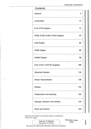 3
3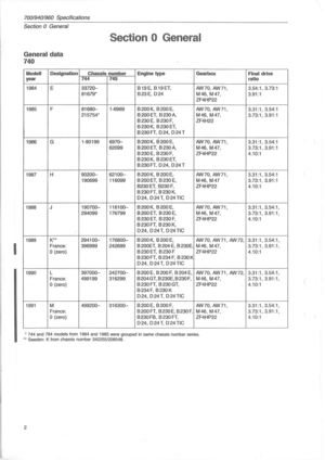 4
4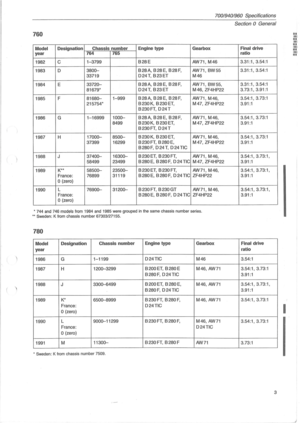 5
5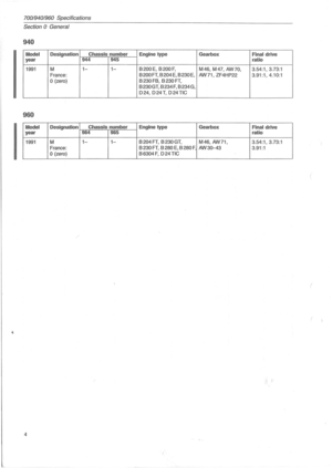 6
6 7
7 8
8 9
9 10
10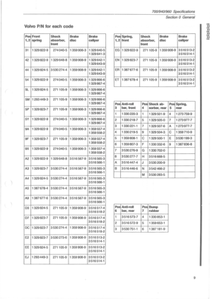 11
11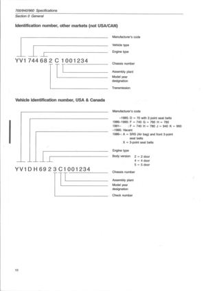 12
12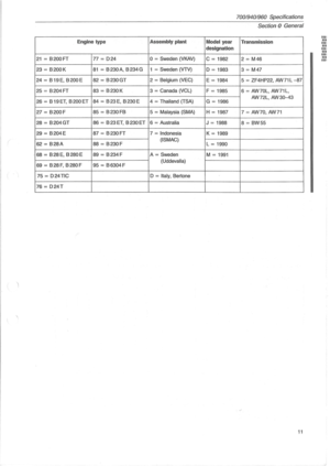 13
13 14
14 15
15 16
16 17
17 18
18 19
19 20
20 21
21 22
22 23
23 24
24 25
25 26
26 27
27 28
28 29
29 30
30 31
31 32
32 33
33 34
34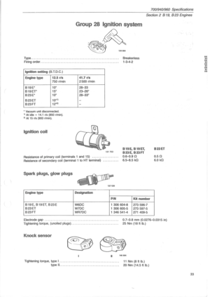 35
35 36
36 37
37 38
38 39
39 40
40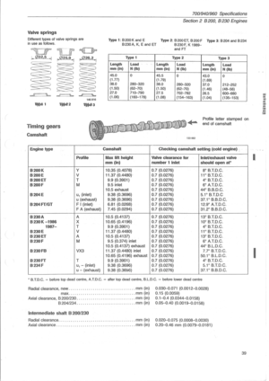 41
41 42
42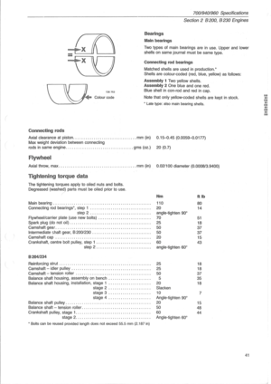 43
43 44
44 45
45 46
46 47
47 48
48 49
49 50
50 51
51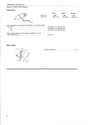 52
52 53
53 54
54 55
55 56
56 57
57 58
58 59
59 60
60 61
61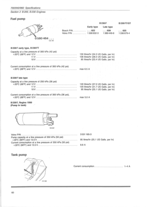 62
62 63
63 64
64 65
65 66
66 67
67 68
68 69
69 70
70 71
71 72
72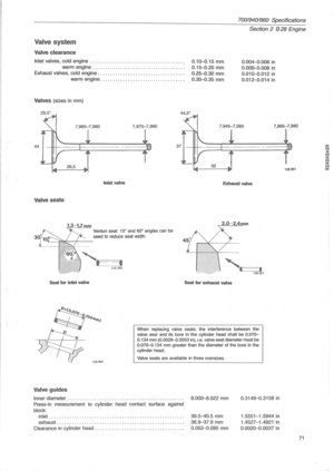 73
73 74
74 75
75 76
76 77
77 78
78 79
79 80
80 81
81 82
82 83
83 84
84 85
85 86
86 87
87 88
88 89
89 90
90 91
91 92
92 93
93 94
94 95
95 96
96 97
97 98
98 99
99 100
100 101
101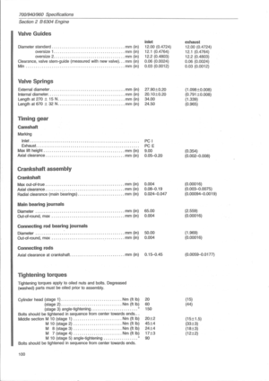 102
102 103
103 104
104 105
105 106
106 107
107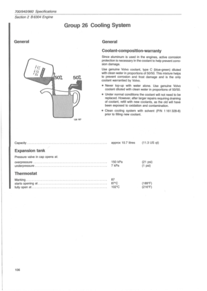 108
108 109
109 110
110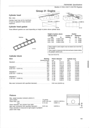 111
111 112
112 113
113 114
114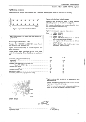 115
115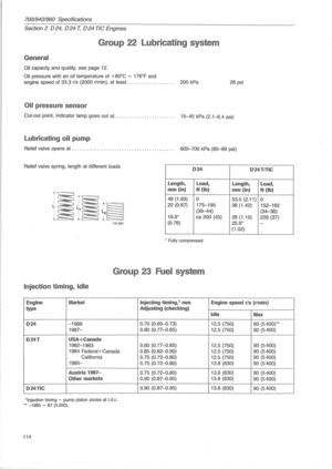 116
116 117
117 118
118 119
119 120
120 121
121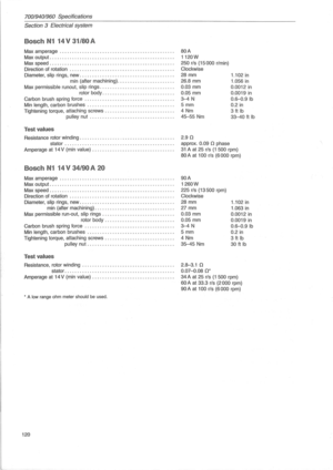 122
122 123
123 124
124 125
125 126
126 127
127 128
128 129
129 130
130 131
131 132
132 133
133 134
134 135
135 136
136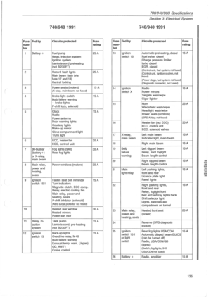 137
137 138
138 139
139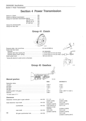 140
140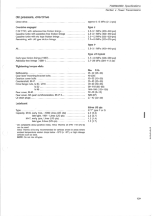 141
141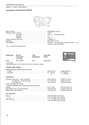 142
142 143
143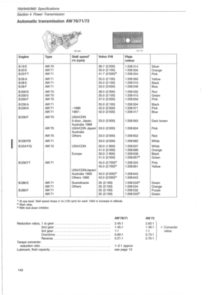 144
144 145
145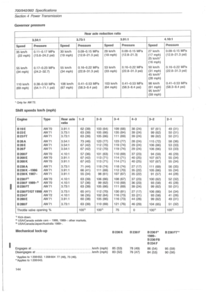 146
146 147
147 148
148 149
149 150
150 151
151 152
152 153
153 154
154 155
155 156
156 157
157 158
158 159
159 160
160 161
161 162
162 163
163 164
164 165
165 166
166 167
167