Page 121 of 168

(
70019401960 Specifications
Section
3 Electrical system
Group 32 Alternator
Bosch K1 14 V 55 A 20
Max amperage ............................................. .
Max output ................................................. .
Max speed ................................................. .
Direction of rotation .
........................................ .
Diameter,
slip rings, new ..................................... .
min (after machining) ...................... .
Max permissible runout, slip rings ............................. .
rotor body
............................ .
Carbon brush spring force
............... .................... .
Min length, carbon brushes .................................. .
Tightening torque, attaching screws
........................... .
pulley nut ................................. .
Test values
Resistance, rotor winding .................................... .
stator
..... ...................................... .
Amperage
at 14 V (min value) ................................ .
, A low range ohm meIer should be used.
Bosch N1 14 V 70 A 20
Max amperage ............................................. .
Max output
................................................. .
Max speed
...................... .. ......................... .
Direction of rotation
......................................... .
Diameter,
slip rings, new ..................................... .
min (after machining)
...................... .
Max permissible runout,
slip rings ............................. .
rotor body
............................ .
Carbon brush spring force
................................... .
Min length, carbon brushes .................................. .
Tightening torque, attaching screws .
.......................... .
pulley nut ................................. .
Test values
Resistance, rotor winding .................................... .
stator
......................................... .. .
Amperage
at 14 V (min value) ................................ .
, A low range ohm meter should be used.
132417
55A
770W
225 rls (13500 r/min)
Clockwise
28 mm
26.8
mm
0.03 mm
0.05 mm
3-4N
5 mm
4 Nm
40 Nm
3.4-3.70
0.14-0.15 0 phase'
1.102 in
1.055 in
0.0012 in
0.0019 in
0.6-0.9Ib
0.2 in
3 ft Ib
30 ft Ib
36 A at 33.3 rls (2000 rpm)
47 A at 50 rls (3000 rpm)
52A at 66.7 rls (4000 rpm)
70A
980W
225 rls (13500 r/min)
Clockwise
28 mm
27 mm
0.03 mm
0.05 mm
3-4N
5 mm
4 Nm
35-45 Nm
3.4-3.70
approx 0.1 0 phase'
1.102 in
1.063 in
0.0012 in
0.0019 in
0.6-0.9Ib
0.2 in
3 ft Ib
30 ft Ib
46 A at 33.3 rls (2000 rpm)
58 A at 50 rls (3000 rpm)
64A at 66.7 rls (4000 rpm)
119
HI Itli til III ·111 III ·tli III ,til
Page 122 of 168

70019401960 Specifications
Section 3 Electrical system
Bosch N1 14 V 31/S0A
Max amperage ............................................. .
Max output
................................................. .
Max speed
................................................. .
Direction
of rotation .................................... ..... .
Diameter,
slip rings, new .................................... . .
min (after machining)
...................... .
Max
permissible runout, slip rings ............................. .
rotor body
............................ .
Carbon brush spring force .
.................................. .
Min
length , carbon brushes .................................. .
Tightening torque, attaching screws
........................... .
pulley nut ................................. .
Test values
Resistance rotor winding ..................................... .
stator
........................................... .
Amperage
at 14 V (min value) ................................ .
Bosch N1 14 V 34 /90 A 20
Max amperage ................................ ............. .
Max output .
............ ........ ......................... ... .
Max speed
............... ................................ .. .
Direction
of rotation ......................................... .
Diameter ,
slip rings, new ..................................... .
min (after machining)
............................... .
Max
permissible run-out , slip rings ............................ .
rotor body
........................... .
Carbon brush spring force
................................. .. .
Min
length, carbon brushes .................................. .
Tightening torque, attaching screws .
.......................... .
pulley nut .................................. .
Test values
Resistance , rotor winding .................................... .
stator
........................................... .
Amperage
at 14 V (min value) ................................ .
* A low range ohm meter should be used.
120
80A
1120W
250 rls (15000 r/min)
Clockwise
28 mm
26.8
mm
0.03 mm
0.05 mm
3-4N
5 mm
4 Nm
45-55 Nm
2.9 Q
approx. 0.09 Q phase
1.102 in
1.056 in
0 .0012 in
0 .0019 in
0.6--0 .9Ib
0.2 in
3 ft Ib
33-40 ft Ib
31 A at 25 rls (1 500 rpm)
80 A at 100 rls (6000 rpm)
90A
1260W
225 rls (13500 rpm)
Clockwise
28 mm
27 mm
0.03 mm
0.05 mm
3-4N
5 mm
4 Nm
35-45 Nm
2.8-3.1
Q
0.07 -0 .08 Q*
1.102 in
1 .063 in
0.0012 in
0 .0019 in
0 .6--0.9Ib
0 .2
in
3 ft Ib
30 ft Ib
34 A at 25 rls (1 500 rpm)
60 A at 33.3 rls (2000 rpm)
90 A at 100 rls (6000 rpm)
Page 123 of 168

Bosch N1 14 V 31/100 A
Max amperage ........................... .................. .
Max output ............................................. 00 •••
Max speed ........................... 0 •••••••••••••••• 0 •••••
Direction of rotation ................ ............ 0 •••••••••••••
Diameter, slip rings, new ..................................... .
min (after machining) .
................ 0 •••• •
Max permissible run-out, slip rings ........................ 0 • 0 ••
rotor body .... o •••••••••••••••••• 0 ••••
Carbon brush spring force ............................. 0 • • 0 •• •
Min length, carbon brushes .................................. .
Tightening torque, attaching screws .
.......................... .
pulley nut .......... o ••••••••••••••••• o •••••
Test values
Resistance, rotor winding .................................... .
( stator ................. 0 ••••••••••••••••••••••• • ••
Amperage at 14 V (min value) ..................... ........ .. 0 •
• A low range ohm meter should be used .
Bosch NC 14 V 60 /120 A
Volvo PiN ............ ................... 0 •••••• ••• ••••••••••
Bosch number ........................... 0 •••••••••• 0 ••••••••
Max amperage ............................................ . .
Max output
................................ 0 •••••••••••••••••
Max speed ......................................... 0" 0 •••••
Direction of rotation ................................ 0 ••• ••••••
Diameter , slip rings, new ........ . 0 ••••••••••••••••••\
••••• •••••
min (after machining) ...................... .
Max permissible run-out,
slip rings ................. 0 •••••••••••
rotor body ........................... .
Carbon brush spring force ...
........................... ..... .
Min length, carbon brushes ... 0 • •••••••••• 0 ••••••• 0' 00.00 •••••
Tightening torque, attaching screws ................. 0 ••••• 0 ••••
pulley nut ........... 0 ••••••••••• 0 •• 0 0 • 0 ••••
Test va lues
Resistance, rotor winding ................... .... 0 •• •••••••••••
stator ..................................... ...... .
Amperage
at 14 V (min value) .................. 0 ••••••••• 0 ••••
Nippon Denso 80 A
Volvo PiN ............. ..................................... .
Nippon Denso number .
................ 0 •••••• 0 ••••• 0 •••••••• •
Max amperage .............. ............................... .
Max output .................... ............................. .
Max speed ............................... 0 ••• ••••••• •••• ••••
Direction of rotation ..... 0 •••••• 0 •••••••••••••••••• 0 ••••••••••
70019401960 Specifications
Section
3 E lectrical system
100A
1400W
250 rls (15000 rpm)
Clockwise
28 mm
27 mm
0.03 mm
0.05 mm
3-4N
5 mm
4 Nm
45-55 Nm
2 .6
n
ca 0.05 n
1 .063 in
0.0012 in
0.0019 in
0 .6-0.9Ib
0.2 in
3 ft Ib
33-40 ft Ib
31 A at 25 rls (1 500 rpm)
100 A at 100 rls (6000 rpm)
3523420
0120465 006
120A
1680W
300 rls (18000 r/min)
Clockwise
15 mm (0.59 in)
14
mm (0. 55 in)
0,003 mm (0.0001 in)
0,005 mm (0.0002 in)
3-5 N (0.3-0.5 kp)
5 mm (0.2 in)
4 Nm (3 ft Ib)
45-55 Nm (33-40 ft Ib)
2,6 n
0,02 n
60 Avid 30 rls (1 800 r/min)
120 Avid 100 rls (6000 r/min)
1398327
100211-8370
80A
1120W
300 rls (18000 r/min)
Clockwise
121
I
III II III II III -II III oil III
j
Page 124 of 168

70019401960 Specifications
Section
3 E lectrical system
Charging regulator , 1982-1984
Early type Late type
Designation , early type . . . . . . . . . . . . . . . . . . . . . . . . . . . . . . . . . . . . . . . Bosch 0 192 052 027
late
type . . . . . . . . . . . . . . . . . . . . . . . . . . . . . . . . . . . . . . . . . Bosch 1 197 311 008
TEST COND IT IO NS
State battery charge ........................... ............ .. .
Air temperature
.......................... ................... .
Temperature ,
warm regulator ............................. .... .
Tes t values
Alternator speed ...... ...................................... .
Engine speed ..
..... .................................. approx
Alternator load ............ .............................. .... .
Control voltage, between B+ and D-alternator terminals:
Cold regulator
(reading taken within 1 min) .. ................... .
Warm regulator (run min. 15 min at 3000 r/min) ................ .
Co ntrol to le ra n ce
Load 55 A alternator to ........ ........... ... ................ .
70A ................................ .................. .
90A ........ .................................. ........ .
The
control voltage should now be between 0 and 0.3 Volt lower than
the previous reading .
• Load achieved when engine running .
Charging regulator , 1985-
TES T CO NDITION S
State of battery charge ........................ ............ .. .
Air temperature
............................................. .
Temperature, warm
regulator ............... .................. .
Tes t values
Alternator speed ............... ............................. .
Engine speed
............................. ............ approx
Alternator load .................. ............................ .
Control voltage, between B+ and D-alternator terminals ........ .
• Load achieved when engine running .
122
In car
min 3/4
+25°C (7rF)
+60-80°C
(140-176 °
F)
100 rls (6000 rpm)
50 rls (3000 rpm)
30-50A*
14.1-14.8V
13.4-14.2V
On tes t b ench
fully charged
+25°C (7rF)
+60°C (140 °F)
100 rls (6000 rpm)
5A
14.4-14.8 V
13.8-14.3 V
47 A (rated output x
0.85)
60 A (rated output x 0.85)
77 A (rated output x 0.85)
In c ar
min 3/4
+25°C (77 °F)
+ 60-80°C
(140-176 °
F)
On tes t be nch
fully charged
+25°C (7rF)
+60°C (140 °F)
100 rls (6000 r/min) 100 rls (6000 r/min)
50 rls (3000 r/min)
30-50A* 5A
13.8-14.6V 14.1-14 .9V
Page 125 of 168

Load
55 A alternator to ............... ............. ....... ... .
.
70A ...................... ........................... . .
80A ..................")
(
Control to le ra nce (on test bench)
Load
55 A alternator to ............... ............. ....... ... .
.
70A ...................... ........................... . .
80A .................. ...................... .......... .
90A ......... ......................................... .
The
control voltage should now be between 0 and 0.3 Volt lower than
the previous reading.
V 16
15,5 .
15
'"
v
15,5
15 .
14,5 14
13,5
70019401960 Specifications
Section 3 E lectrical system
47 A (rated output x 0.85)
60 A (rated output x 0.85)
68 A (rated output x 0.85)
77 A (rated output x 0.85)
13 30 20 10 0 10 20 30 40 50 60 70 80 90C' 13 30 20 10 0 10 20 30 40 50 60 70 80 90100 110C'
Exte rn al volt age- te m perature 5A load
1:l9000
Int erri al volt age- te mp erature 5A load
G ro up 33 S ta rt er m otor
Bosch GF 12V 1.1 kW (00013111 .. )
V olvo PIN 463856 , 464 316, 464317,1346 707
Direction of rotation (viewed towards pinion) ............... .... . .
Output . . ......................................... , ......... .
Test values , mechan ical
Armature end clearance ....... ................... .......... . .
Brush spring force
.......................................... .
Distance from pinion to ring gear ... .
.......................... .
Frictional torque, armature brake ............................ .. .
Pinion
idling torque ........... .. ...................... ..... .. .
Backlash ..................... .............................. .
Pinion
modulus . .. .............................. ............ .
Commutator , min . diameter
................................... .
Carbon brushes, min
length .. ............................ .... .
Max
radial runout, commutator and armature body ... ........... .
Clockwise
1 .1 kW (1.5 hp)
0.01-0.3 mm
18-21 N
1.0-3.8 mm
25-40 Ncm
14-22 Ncm
0 .
3-0.5 mm
2.12 mm
33.5 mm
13 mm
0 .
05 mm 0.000
4-0
.012 in
4.1-4.7Ib
0 .039-0.149 in
2.2-3.5 in. lb.
1 .7 - 2.6 in. lb.
0.0118-0.0196 in
0.0835 in
1 .319 in
0 .512 in
0 .0019 in
1 39001
123
III III III III III ,11, III ·111 III
Page 126 of 168

70019401960 Specifications
Section 3 Electrical system
Test
values, electr ica l
Unloaded starter motor: 11.5 V and max. 70 A .................. .
Locked starter motor: 7.4 V and
480-560A ..................... .
6.5 V and
410-490A ..................... .
Minimum cut-in voltage, control solenoid
....................... .
Bosch OW 12 V 1.4 kW (0001108 ... )
Volvo PIN 1 357199, 1 398702, 1 398764
3523301, 3523302,
3523303
Direction of rotation (viewed towards pinion) .................... .
Output ...................................................... .
Test values, mechanical
Armature end clearance ..................................... .
Distance
from pinion to ring gear .............................. .
Frictional torque, armature brake
................ ... ........... .
Pinion idling torque
.......................................... .
Backlash
.................... ............................... .
Pinion modulus
............................................. .
Commutator, minimum diameter
.............................. .
Carbon brushes, min length
.................................. .
Max. radial run-out, commutator and armature .................. .
Test values, electr ica l
Unloaded starter motor 11.5 V and max. 75 A ..... .............. .
Starter motor locked, 4.5 V and
625-800 A ..................... .
Lowest cut-in voltage, control solenoid
......................... .
Bosch OW(R) 12V 1,7 kW (0001110063)
Volvo PIN 1 363912
Direction of rotation (viewed towards pinion) .................... .
Output ................................................... .. .
Test values, mechanical
Armature end clearance ..................................... .
Distance from pinion
to ring gear .............................. .
Frictional torque, armature brake
.............................. .
Pinion idling torque
........................................... '
Backlash ................................................... .
Pinion modulus
............................................. .
Commutator, minimum diameter
............................. . .
Carbon brushes, min length .
................................. .
Max. radial run-out, armature
................................. .
commutator
............................... .
Test values, electr ica l
Unloaded starter motor, 11.2 V and max. 95 A .................. .
Starter motor locked, 3.8 V and
650-840 A ..................... .
Lowest cut-
in voltage, control solenoid ......................... .
124 min
125
rls (7500 rpm)
OrIs and min 16 Nm
OrIs and min 15 Nm
8V
Clockwise
1.4
kW (1.9 hpj
0.05-0.4
mm
2 .0-3.0 mm
0.9-1.4 Nm
0.12 -0.18 Nm
0.3-0.6 mm
2.12 mm
31.2 mm
8.0 mm
0.05 mm
min 48 rls (2900 rpm)
OrIs and min 16 Nm
7.3V
Clockwise
1.7 kW (2.3
hpj
0.05-0.04
mm
2-3 mm
0.9-1.5 Nm
0.12-0.18 Nm
0 .3-0.6 mm
2.11 mm
31.2 mm
6mm
0.05 mm
0 .01 mm
min 2800 r/min
OrIs
7.3V
0.0020-0.0158 in
0.0788-0 .1182
3 .9-6.5 in. lb.
2.4-3.4 in. lb.
0.014-0.023 in
0.0835 in
1.229 in
0.315 in
0.0019 in
(0.002-0.016 in)
(0.08-0.12 in)
(8-13
in Ib)
(1.1-1.6 in Ib)
(0.01-0.024 in)
(0.831 in)
(1.23 in)
(0.24 in)
(0. 002 in)
(0.0004 in)
Page 127 of 168

Volvo PIN 1 257939
Direction of rotation (viewed towards pinion) .................... .
Output ..................................................... .
Test")
(
Bosch JF 12V 2 kW (0001362 ... )
Volvo PIN 1 257939
Direction of rotation (viewed towards pinion) .................... .
Output ..................................................... .
Test va lu es , mechanical
Armature end clearance ..................................... .
Carbon brush spring force .
.................................. .
Distance from pinion to ring gear ..
............................ .
Frictional torque, armature brake .............................. .
Pinion
idling torque ........................................ .. .
Backlash ...... ............................................. .
Pinion
modulus ............................................. .
Commutator, minimum diameter
.............................. .
Carbon brushes, min
length .................................. .
Max .
radial run-out, commutator and armature .................. .
Test v alues , e lec tric al
Unloaded starter motor, 11.5 V and max. 95 A .................. .
Starter motor
locked, 4.5 V and 700-880 A .................. ' .. .
Lowest cut-in
voltage, control solenoid ......................... .
Bosch EV 12V 2,2 kW (0001218 ... )
Volvo PIN 1 328392
Direction of rotation (viewed towards pinion) .................... . ,/ Output ..................................................... .
Test values , mechan ical
Armature end clearance ..................................... .
Distance from pinion to ring gear
.............................. .
Frictional torque, armature brake .............................. .
Pinion
idling torque .......................................... .
Backlash.. . . .. ,.,',.,." ..... " .. " ..... , ..... ,., .. ,., .. .. .
Pinion
modulus. , .... , . ... , . , ............... ........ , .... , .. .
Commutator, minimum diameter
.. , , .. , .. , ....... , .... , . , .. , .. .
Carbon brushes, min
length, , ........... , .... , .... , .... , .. , .. ,
Max. radial run-out, armature .. , .. , . . , , , .............. , . , .. , .. .
commutator
....... , ..... , .. , , .... , . , .. , .. .
Test va lu es , e lectr ica l
Unloaded starter motor, 10.5 V and max. 160 A ... , .... . , . , .. , .. .
Starter motor
locked, 3.0V and 720-950 A " ., ........... , ..... .
Lowest cut-in
voltage, control solenoid, , , , ....... , .. , .. , . , .. , .. ,
70019401960 Specifications
Section 3 Electrica l system
Clockwise
2 kW (2.7 hpj
0.01-0.3 mm
23-25 N
2.5-3 mm
0.44-0,74 Nm
0.27-0 .39 Nm
0.35-0.60 mm
2.12 mm
42,5 mm
8.5 mm
0,05 mm
(0.0004-0 .012 in)
(5,2-5.6 Ib)
(0.1-0 .12 in)
(3.9-6 .5 in Ib)
(2.4-3.4 in Ib)
(0.014-0.024 in)
(0.0835 in)
(1.67 in)
(0.33 in)
(0.002 in)
min 108 rls (6500 rpm)
OrIs and min 44 Nm
7.5V
Clockwise
2,2 kW (3.0 hpj
0.05-0.3 mm
2-3 mm
1.0-1.5 Nm
0,27-0.35 Nm
0 .3-0.6 mm
2,12 mm
28 ,9 mm
7.0 mm
0 .05 mm
0,01 mm
min
70 rls (4200 rpm)
OrIs and min 25 Nm
7.8V
0.0020-0.0118 in
0.079-0.118 in
8.8--13.2 in Ib
2.4-3.1 in Ib
0.0118--0.023 in
0.0835 in
1.139 in
0.276 in
0 .0019 in
0,0004 in
125
J
Page 128 of 168

Output . . . . . . . . . . . . . . . . . . . . . . . . . . . . . . . . . . . .")
70019401960 Specifications
Section
3 Electrical system
HITACHI 12 V 1.4 kW 5114-232 A
(Volvo PIN 1 357373)
Output . . . . . . . . . . . . . . . . . . . . . . . . . . . . . . . . . . . . . . . . . . . . . . . . . . . . . . 1.4 kW (1.9 hpj
Test values , mechanical
Armature axial clearance ..................................... .
Brush spring tension
........................................ .
Pinion modulus ... .......................................... .
Idle clearance .............................................. .
Minimum diameter of commutator
.................... ......... .
Minimum
length of brushes .......................... ......... .
Test values, electr ica l
Unloaded starter motor, 12 V and max. 60 A .................... .
Starter motor under
load: 10.3 V, 200 A ........................ .
Starter motor
locked: 6 V and max. 650 A ...................... .
Lowest cut-in
voltage, control solenoid ........ ... .............. .
HITACHI 12 V 2.0 kW 513-91
(Volvo PIN 1 328391)
Direction of rotation (viewed towards) .......................... .
Output ..................................................... .
Test values, mechanical
Armature end clearance ..................................... .
Brush spring force
.......................................... .
Pinion modulus ............................................. .
Pinion backlash ............................................. .
Commutator, min diameter ..
................................. .
Carbon brushes, min
length .................................. .
Test values, electr ical
Unloaded starter motor, 11 V & max 140 A ..................... .
Loaded starter motor, 8.8
V, 300 A. ............................ .
Locked starter motor, 3
V, max 880 A .......................... .
Minimum cut-in
voltage, control solenoid ....................... .
126
0 .03-0.1 mm (0.0012-0.0039 in)
13.7-17. 7 N (1.4-1.8 kp)
2.12 mm
0.3-1.5 mm (0.012 -0.060 in)
39 mm
(0.1536 in)
11 mm (0.433 in)
min. 117
rls (7000 rpm)
min 37
rls (2200 rpm) and min. 4.6 Nm
OrIs and min. 19 Nm
8V
Clockwise
2.0
kW (2.7 hpj
0.2-0.5 mm (0.0079-0.0197 in)
26.5-32.4 N (6.0-7.3 Ib)
2.12 mm (0.0835 in)
0.3-1.5 mm(0.0118-0.0591 in)
35
.5 mm (1.40 in)
9 mm
(0.35 in)
min 65
rls (3900 rpm)
min 25
rls (1 500 rpm) and min 8.3 Nm
OrIs & min 24.5 Nm
8V
 1
1 2
2 3
3 4
4 5
5 6
6 7
7 8
8 9
9 10
10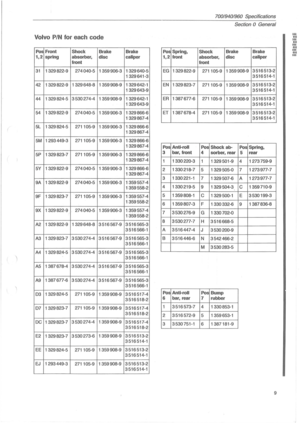 11
11 12
12 13
13 14
14 15
15 16
16 17
17 18
18 19
19 20
20 21
21 22
22 23
23 24
24 25
25 26
26 27
27 28
28 29
29 30
30 31
31 32
32 33
33 34
34 35
35 36
36 37
37 38
38 39
39 40
40 41
41 42
42 43
43 44
44 45
45 46
46 47
47 48
48 49
49 50
50 51
51 52
52 53
53 54
54 55
55 56
56 57
57 58
58 59
59 60
60 61
61 62
62 63
63 64
64 65
65 66
66 67
67 68
68 69
69 70
70 71
71 72
72 73
73 74
74 75
75 76
76 77
77 78
78 79
79 80
80 81
81 82
82 83
83 84
84 85
85 86
86 87
87 88
88 89
89 90
90 91
91 92
92 93
93 94
94 95
95 96
96 97
97 98
98 99
99 100
100 101
101 102
102 103
103 104
104 105
105 106
106 107
107 108
108 109
109 110
110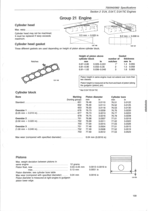 111
111 112
112 113
113 114
114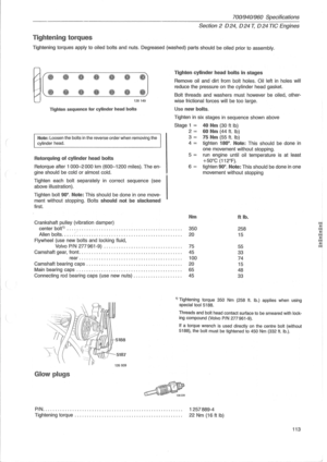 115
115 116
116 117
117 118
118 119
119 120
120 121
121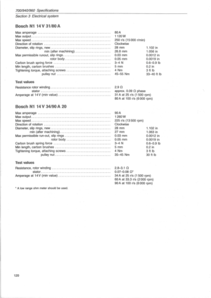 122
122 123
123 124
124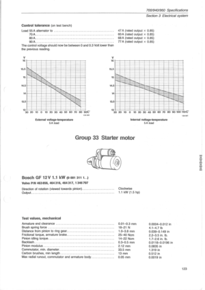 125
125 126
126 127
127 128
128 129
129 130
130 131
131 132
132 133
133 134
134 135
135 136
136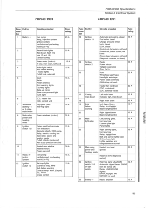 137
137 138
138 139
139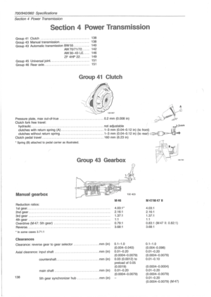 140
140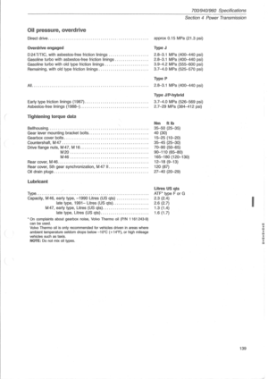 141
141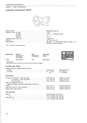 142
142 143
143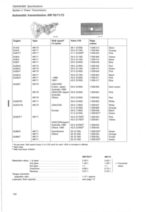 144
144 145
145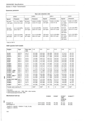 146
146 147
147 148
148 149
149 150
150 151
151 152
152 153
153 154
154 155
155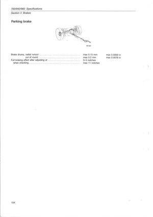 156
156 157
157 158
158 159
159 160
160 161
161 162
162 163
163 164
164 165
165 166
166 167
167