1982 VOLVO 940 checking oil
[x] Cancel search: checking oilPage 19 of 168

(
70019401960 Specifications
Section
2 B 19, B 23 Engines
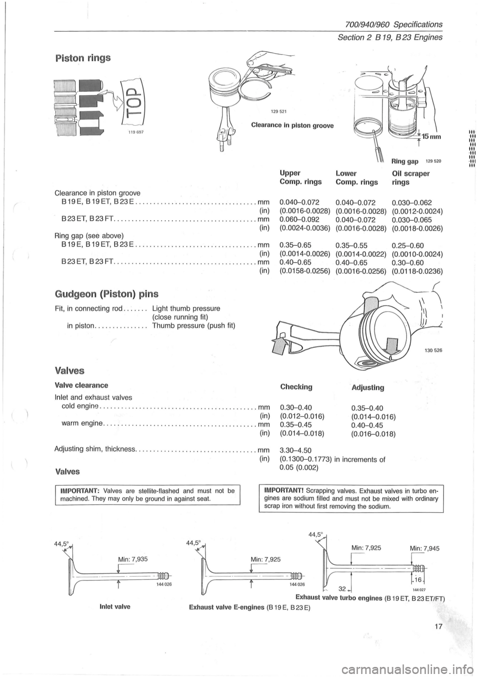
P iston rings
129521
Clearance In piston groove
Clearance in piston groove
819 E, 819 ET, 823 E .................................. mm
(in)
823ET, 823FT .............. .......................... mm
(in)
Ring gap (see above)
819E, 819ET, 823E .................................. mm
(in)
823ET, 823FT ................ .......... .............. mm
Gudgeon (Piston ) pins
Fit, in connecting rod. . . . . .. Light thumb pressure
(close running fit)
in piston. . . . . . . . . . . . . .. Thumb pressure (push fit)
Valves
Valve clearance
Inlet
and exhaust valves
(in)
cold engine ............................................ mm
(in) warm engine ........................................... mm
(in)
Adjusting shim, thickness .................................. mm
(in)
Valves
Upper
Camp.
rings
0.040-0 .072
(0. 0016-0.0028)
0.060-0 .092
(0.0024-0.0036)
0 .35-0.65
(0.0014 -0 .0026)
0.40-0 .
65
(0.0158-0.0256)
Checking
0.30-0.40
(0.012-0.Q16)
0.35-0.45
(0.014-0.018)
3 .
30-4.50
Ring gap 129 520
Lower Oil scraper
Camp.
rings rings
0.040-0.072 0.030-0.062
(0.0016 -0 .0028) (0.0012 -0.0024)
0.040-0.072 0.030-0.065
(0.0016-0.0028) (0.0018-0.0026)
0.35-0.55 0.25-0.60
(0.0014-0.0022) (0.0010-0.0024)
0.40-0.65 0.30-0.60
(0.0016-0.0256) (0.0118-0.0236)
'Adjusting
0.35-0.40
(0. 014-0 .016)
0.40-0.45
(0. 016-0.018)
(0.1300-0 .1773)
in increments of
0.05 (0.002)
IMPORTANT: Valves are stellite-flashed and must not be machined . They may only be ground in against seat. IMPORTANT! Scrapping valves. Exhaust valves in turbo engines are sodium filled and must not be mixed with ordinary
scrap iron without first removing the sodium.
Min: 7,935
Inlet valve
44,5°
44,5 °
Min: 7,945
144027
Exhaust valve turbo engines (8 19 ET, 823 ET/FT)
Exhaust valve E-engines (8 19 E, 823 E)
17
III' III III
III
III ,111 III ·111 III
Page 39 of 168

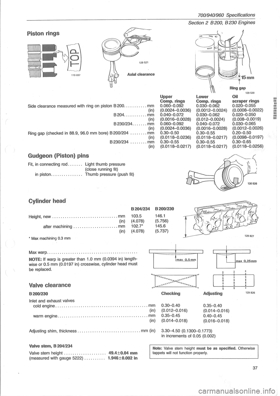
Piston rings
129521
Axial clearance
Side clearance measured with ring on piston 8200 ........... mm
(in)
8204 ........... mm
(in)
8230/234 ....... mm (in)
Ring gap (checked
in 88.9, 96.0 mm bore) 8200/204 ........ mm (in) 8230/234 ........ mm
Gudgeon (Piston) pins
Fit, in connecting rod. . . . . .. Light thumb pressure
(close running fit) (in)
in piston.
. . . . . . . . . . . . .. Thumb pressure (push fit)
Cylinder head-
Height, new ............................... mm
(in)
after machining
..................... mm
(in)
• Max machining 0.3 mm
B204/234
103.5
(4.078)
102.7*
(4.078)
Max warp .......................................... .
NOTE: If warp is greater than 1.0 mm (0.0394 in) length
wise or 0.5 mm (0.0197 in) crosswise, cylinder head must
be replaced.
Valve clearance
B200/230
Inlet and exhaust valves
cold
engine ............................................ mm
(in)
warm engine
........................................... mm
(in)
70019401960 Specifications
Section 2 B 200, B 230 Engines
Upp er Compo rings 0.060-0.092
(0.0024-0.0036)
0.040-0.072 (0.0016-0.0028)
0.060-0.092 (0.0024-0.0036)
0.30-0.50
(0.0118--0.0236)
0.30-0.55
(0.0118--0.0217)
B200/230
146.1
(5.756)
145.6
(5.737)
Checking
0.30-0.40 (0.012-0.Q16)
0.35--0.45 (0.014-0.018)
Lower Compo rings 0.030-0.062 (0.0012-0.0024)
0.030-0.062 (0.012-0.0024)
0.040-0.072 (0.0016-0.0028)
0 .30-0.55
(0.0118--0.0217)
0.30-0.55
(0.0118--0.0217)
Adjusting
0.35--0.40
(0.014-0.016)
0.40-0.45 (0.016-0.018)
Ring gap 129520 Oil scraper rings 0.020-0.055
(0.0008--0.0022)
0.020-0.050 (0.008--0.0019)
0.030-0.065 (0.0012-0.0026)
0.20-0.50 (0.0098--0.0197)
0.30-0.65 (0.0118--0.0256)
max o 25mm
129 826
Adjusting shim, thickness .............................. mm (in) 3.30-4.50 (0.1300-0.1773)
in increments of 0.05 (0.002)
Valve stem, B 204/234
Valve stem height . . . . . . . . . . . . . . . . . . .. 49.4±0.04 mm
(measured with gauge 5222) . . . . . . . . .. 1.946±0.002 in
Note: Valve stem height must be as specified. Otherwise
tappets will not function properly.
37
III III
ill III ill
IN liN
t·
Page 66 of 168

700/940/960 Specifications
Section 2' 8200,8230 Engines
Group 25 Intake and exhaust systems
Turbo engines
'-198~
Engine type .... ; ......... . , ............ .. .............
Charg~ pressure, at full load and ................... r/min
checking
.. ................... kPa (psi)
setting. . . . . . . . . . . . . . . . . . . . .
.. kPa (psi)
Charge air overpressure, switch opens at ....... kPa
(psi)
Charge air pressure, switch closes at ........... kPa (psi)
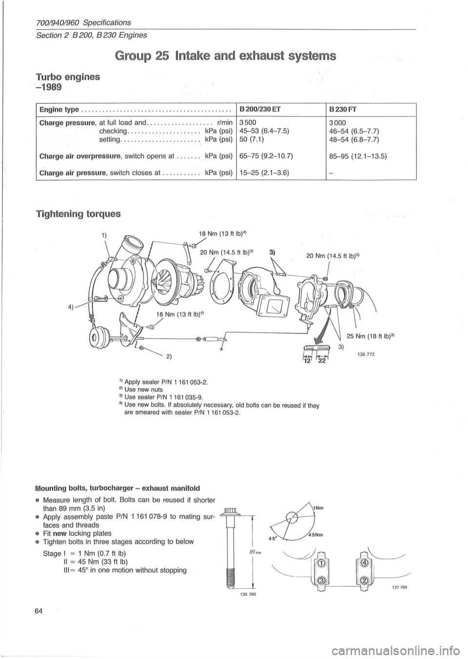
Tightening torques
4) 18 Nm (13 ft IW)
/
1) Apply sealer PIN 1 161 053-2. 2) Use new nuts
3) Use sealer PIN 1161 035-9.
8200/230 ET
3500
45-53 (6.4-7.5)
50 (7.1)
65-75 (9.2-10.7)
15-25 (2. 1-3.6)
3)
4) Use new boils. If absolutely necessary, old boils can be reused if they
are smeared with sealer PIN 1161053-2.
Mounting bolts, turbocharger -exhaust manifold
• Measure length of bolt. Bolts can be reused if shorter
than
89 mm (3.5 in)
• Apply assembly paste PIN 1 161 078-9 to mating sur-<=;==;=""-~
faces and threads
• Fit new locking plates
•
Tighten bolts in three stages according to below
64
Stage I = 1 Nm (0.7 ft Ib)
II = 45 Nm (33 ft Ib)
III = 45° in one motion without stopping
89mm
135780
~Nm
s::L).Nm
8230FT
3000
46-54 (6.5-7.7)
48-54 (6.8-7.7)
85-95 (12 .1-13.5)
-
136772
Page 72 of 168

70019401960 Specifications
Section'-2" B 28 Engine
Group 21 Engine block
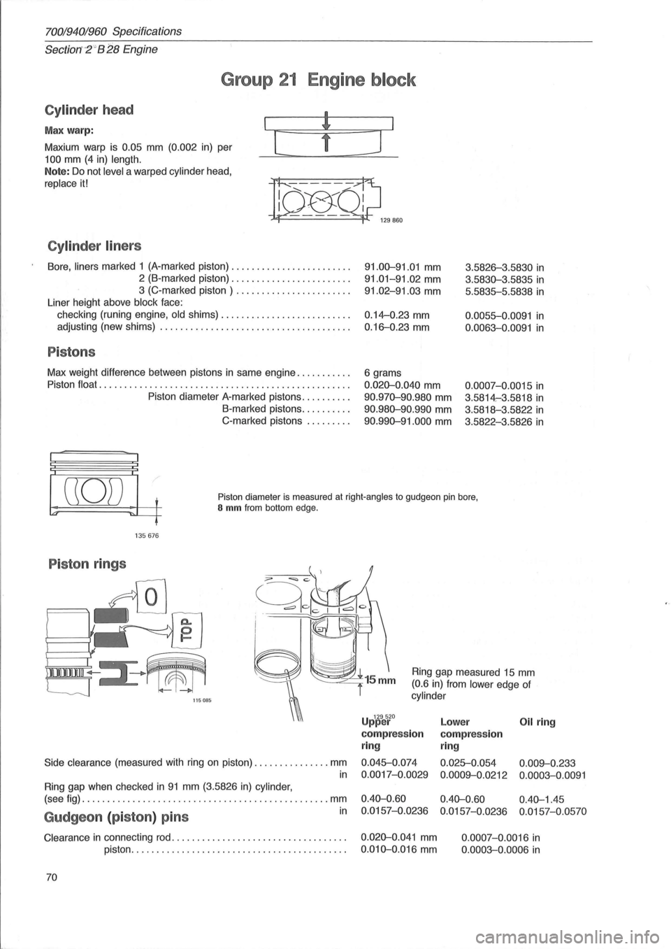
Cylinder head
Max warp:
Maxium warp is
0.05 mm (0.002 in) per
100 mm (4 in) length.
Note: Do not level a warped cylinder head,
replace it!
Cylinder liners
[
Bore, liners marked 1 (A-marked piston) ....................... .
2 (B-marked piston) ....................... .
3 (C-marked piston) ...................... .
Liner height above
block face:
checking (runing engine,
old shims) ....................... .. .
adjusting (new shims)
..................................... .
Pistons
Max weight difference between pistons in same engine .......... .
Piston
float ................................................. .
Piston diameter A-marked pistons
......... .
B-marked pistons
......... .
C-marked pistons
........ .
]
91.00-91.01 mm
91.01-91.02 mm
91.02-91.03 mm
0.14--0.23 mm
0.16-0.23 mm
6 grams
0.020-0.040 mm
90.970-90.980 mm
90.980-90.990 mm
90.990-91.000 mm
3.5826-3.5830 in
3.5830-3.5835 in
5.5835-5.5838 in
0.0055-0.0091 in
0.0063-0.0091 in
0.0007-0. 0015 in
3.5814-:3.5818 in
3.5818-3.5822 in
3.5822-3.5826 in
((0)) t
'" ~L-f
Piston diameter is measured at right-angles to gudgeon pin bore, S mm from bottom edge.
135676
Piston rings
/,
I 111111111 ~III
'--J 115085
Side clearance (measured with ring on piston) ............... mm
in
Ring gap when checked in 91 mm (3.5826 in) cylinder,
Ring gap measured 15 mm
(0.6 in) from lower edge of
cylinder
U 129520 pper
compression
ring
0.045-0.074
0.0017-0.0029
Lower Oil ring
compression
ring
0.025-0.054 0.009--0.233
0.0009--0.0212 0.0003-0.0091
(see fig) ................................................. mm 0.40-0.60 0.40-0.60 0.40-1.45
in 0.0157-0.0236 0.0157-0.0236 0.0157-0.0570 Gudgeon (piston) pins
Clearance in connecting rod. . . . . . . . . . . . . . . . . . . . . . . . . . . . . . . . . . . 0.020-0.041 mm
piston. . . . . . . . . . . . . . . . . . . . . . . . . . . . . . . . . . . . . . . . . . .
0.010-0.016 mm
70 0.0007-0.0016
in
0.0003-0.0006 in