1982 CHEVROLET CAMARO check engine
[x] Cancel search: check enginePage 736 of 875

GM – CAMARO 1982-1992 – Repair Guide (Checked by WxMax) 736
The mass air flow systems measure the
mass of air that is drawn into the
engine cylinders, rather than just the vo lume. The sensor contains a hot-wire
sensing unit, which is made up of an electronic balanced bridge network.
Whenever current is suppli ed to the sensor, the bridge is energized and the
sensing hot-wire is heated. As the air enter s the mass air flow sensor, it passes
over and cools the hot wire. When the hot wire is cooled, it's resistance changes
and additional current is needed to k eep the bridge network balanced. This
increase in current is sent to the computer as a voltage signal and is used to
calculate the mass of the incoming air. The ECM uses this information to\
determine the duration of fuel injection pulse, ignition timing and EGR operation.
The speed density systems calculate the volume of air moving through the
intake. The ECM establishes the speed fact or through a signal from the ignition
module. The Manifold or Intake Air Temperature (MAT/IAT) and the Engine
Coolant Temperature (ECT) sensors work together to assure that proper
temperature information gets to the ECM wh ile the Manifold Absolute Pressure
(MAP) sensor monitors the changes in m anifold pressure which results from
changes in engine loading. These three se nsors contribute to the density factor.
Together, these inputs (engine speed, coolant temperature sensor, etc ...) are
the major determinants of the air/fuel mixture delivered by the fuel injection
system.
The following engines and fuel managem ent systems are covered in this
section:
• 1985-1989 2.8L MPFI - Mass Air Flow
• 1990-1992 3.1L MPFI - Speed Density
• 1985-1989 5.0L and 5.7L TPI - Mass Air Flow
• 1990-1992 5.0L and 5.7L TPI - Speed Density
Relieving Fuel System Pressure
1. Disconnect the negative battery cable to prevent fuel discharge if the key
is accidentally turned to the RUN position.
2. Loosen the fuel filler cap to reliev e the tank pressure and do not tighten
until service has been completed.
3. Connect J-34730-1 fuel pressure gauge or equivalent, to the fuel
pressure test valve. Wrap a shop towel around the fitting while
connecting the gauge to prevent spillage.
4. Place the end of the bleed hose into a suitable container and open the
valve to relieve the fuel system pressure.
ELECTRIC FUEL PUMP
REMOVAL & INSTALLATION
The fuel pump is part of t he fuel sender assembly located inside the fuel tank.
Page 739 of 875

GM – CAMARO 1982-1992 – Repair Guide (Checked by WxMax) 739
3. Make sure the ignition switch has
been in the OFF position for at least 10
seconds and that all accessories are OFF.
4. Turn the ignition switch ON and the pump will run for about 2 seconds.
Note the system pressure with t he pump running, it should be between
40-47 psi.
The ignition switch may have to be cycled to the ON position more than once to
obtain maximum pressure. It is also norma l for the pressure to drop slightly
when the pump first stops, but it should then hold steady.
5. If the pressure is not as specified, verify that fuel pump operation is
heard in the tank.
6. If fuel pump operation is not heard, inspect the fuel pump relay and
wiring.
7. If fuel pump operation is heard, inspect the filter and lines for restriction.
8. Start the engine and make sure the pr essure decreases about 3-10 psi at
idle.
9. If fuel pressure does not decrease, inspect the fuel pressure regulator
and hose.
10. Disconnect the fuel pressure gauge.
THROTTLE BODY
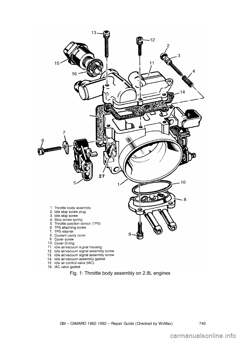
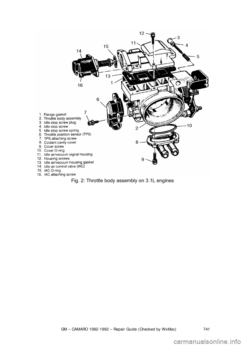
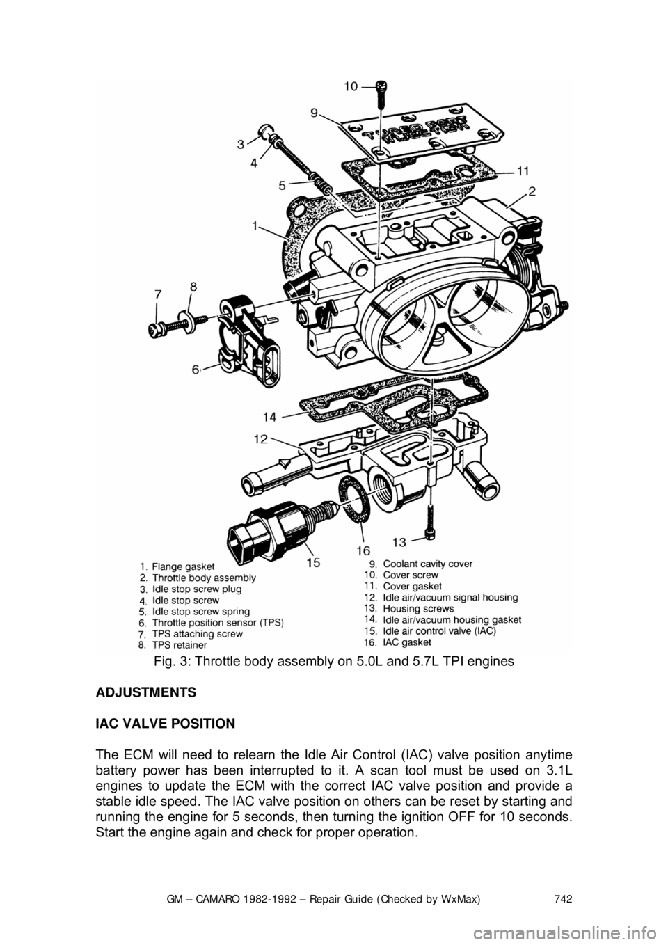
REMOVAL & INSTALLATION 1. Disconnect the negative (-) battery c able and partially drain the radiator.
2. Remove the air inlet duct and unplug the IAC and TPS electrical connectors.
3. Label and disconnect the vacuum and coolant lines.
4. Disconnect the accelerator, thro ttle valve (transmission control) and
cruise control cables, as applicable.
5. Remove the throttle body attaching bolts, then separate the throttle body from the plenum.
6. Discard the gasket.
To install: 7. Install the throttle body to the plenum using a new gasket. Tighten the \
bolts to specification.
8. Engage the accelerator, throttle valve and cruise control cables, as
necessary. Make sure that the link ages do not hold the throttle open.
9. Connect the vacuum and coolant lines.
10. Install the air inlet duct and plug the IAC and TPS electrical connectors
into their sockets.
11. Connect the negative (-) battery cable and refill the radiator.
12. With the engine OFF, check to s ee that the accelerator pedal is free.
Depress the pedal to the floor and release.
Page 740 of 875

GM – CAMARO 1982-1992 – Repair Guide (Checked by WxMax) 740
Fig. 1: Throttle body assembly on 2.8L engines
Page 741 of 875

GM – CAMARO 1982-1992 – Repair Guide (Checked by WxMax) 741
Fig. 2: Throttle body assembly on 3.1L engines
Page 742 of 875

GM – CAMARO 1982-1992 – Repair Guide (Checked by WxMax) 742
Fig. 3: Throttle body assembly on 5.0L and 5.7L TPI engines
ADJUSTMENTS
IAC VALVE POSITION
The ECM will need to relearn the Idle Ai r Control (IAC) valve position anytime
battery power has been interrupted to it. A scan tool must be used on 3.1L
engines to update the ECM with the corre ct IAC valve position and provide a
stable idle speed. The IAC valve position on others can be reset by starting and
running the engine for 5 seconds, then turning the ignition OFF for 10 seconds.
Start the engine again and che ck for proper operation.
Page 743 of 875

GM – CAMARO 1982-1992 – Repair Guide (Checked by WxMax) 743
MINIMUM IDLE SPEED
The minimum idle speed should onl
y be adjusted under two conditions:
If the throttle body has been replaced.
After every other possible cause for the in correct idle speed has been explored.
There are many possible causes for incorre ct idle speed, most of which require
a high level of diagnostic skill as well as expensive testing equipment. Check
the vehicle for vacuum leaks, incorrect valve or ignition timing, deposit
accumulation in the throttle bore or valve, sticking throttle linkage or bent throttle
valves. If the vehicle will still not idle pr operly after checking these areas, it
should be diagnosed by a professional.
1. Pierce the idle stop screw with an awl. Apply leverage to remove it.
2. Make sure the IAC valve is connect ed. Short the A and B terminals of the
ALDL connector together with a length of wire.
3. Turn the ignition to the ON positi on, but do not start the engine. Wait at
least 30 seconds before proceeding.
4. With the ignition ON, disconnect the IAC valve connector.
5. Separate the set-timing connector. Th is eliminates the possibility of
changes in engine speed due to variations of engine timing.
6. Start the engine and remove t he wire shorting the A and B terminals
together. It may be necessary to hold the throttle open slightly to prevent
the engine from stalling.
7. Allow the engine to reach no rmal operating temperature.
8. Adjust the idle speed to the following: a. 2.8L Engines - 450-550 rp m A/T or 550-650 rpm M/T
b. 3.1L Engines - Refer to the underhood emissions sticker
c. 5.0L and 5.7L TPI engines - 400-450 rpm.
If these figures differ from t hose on the underhood emissions
sticker, always follow the specifications on the emissions sticker.
9. Turn the ignition OFF and connect the IAC valve harness. On models up
to 1989, adjust the Throttle Position Sensor.
THROTTLE POSITION SENSOR (TPS) 1. Install three jumper wires betw een the TPS and the harness connector.
2. Use a digital voltmeter connected to terminals A and B of the TPS.
3. Turn the ignition switch ON , but do not start the engine.
4. Loosen the TPS attaching screws and adj ust the sensor to the following:
a. 2.8L Engines - 0.50-0.60 volts
b. 5.0L and 5.7L TPI Engines - 0.47-0.61 volts
5. Tighten the attaching screws, then check that the reading has not been
disturbed.
6. With the ignition OFF, remove the jumper wires. Reconnect the TPS
harness.
Page 744 of 875

GM – CAMARO 1982-1992 – Repair Guide (Checked by WxMax) 744
7. Start the engine and che
ck for proper operation.
FUEL INJECTORS
REMOVAL & INSTALLATION
Use care in removing injectors to prev ent damage to the electrical connector
pins and the nozzle. The fuel injector is serviced as a complete assembly only.
Since it is an electrical compon ent, DO NOT immerse it in a cleaner.
2.8L AND 3.1L ENGINES 1. Disconnect the negative battery cable.
2. Relieve the fuel system pressure.
3. Remove the intake plenum and the fuel rail assembly.
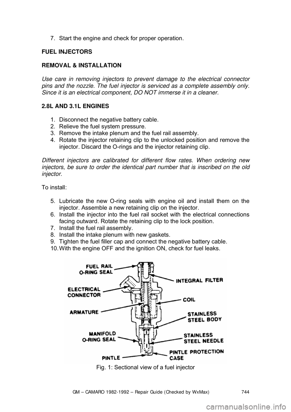
4. Rotate the injector retaining clip to the unlocked position and remove the
injector. Discard the O-rings and the injector retaining clip.
Different injectors are calibrated for different flow rates. When ordering new
injectors, be sure to order the identical part number that is inscribed on the old
injector.
To install: 5. Lubricate the new O-ri ng seals with engine oil and install them on the
injector. Assemble a new reta ining clip on the injector.
6. Install the injector into the fuel ra il socket with the electrical connections
facing outward. Rotate the retaini ng clip to the lock position.
7. Install the fuel rail assembly.
8. Install the intake pl enum with new gaskets.
9. Tighten the fuel filler cap and connect the negative battery cable.
10. With the engine OFF and the igniti on ON, check for fuel leaks.
Fig. 1: Sectional view of a fuel injector
Page 746 of 875

GM – CAMARO 1982-1992 – Repair Guide (Checked by WxMax) 746
5.0L AND 5.7L TPI ENGINES
1. Disconnect the negative battery cable.
2. Relieve the fuel system pressure.
3. Remove the intake plenum and runners.
4. Remove the fuel rail assembly.
5. Rotate the injector retaining clip to the unlocked position and remove the
injector. Discard the O-rings and the injector retaining clip.
There are two different injector part numbers for the 5.0L and the 5.7L engine.
Do not intermix injectors with different part numbers, as this will result in engine
roughness and excessive emissions. When or dering new injectors, be sure to
order the identical part number that is inscribed on the old injector. However, if a
complete set of injectors is being repl aced, either part number for that engine
application may be used.
To install:
6. Lubricate the new O-ri ng seals with engine oil and install them on the
injector. Assemble a new reta ining clip on the injector.
7. Install the injector into the fuel ra il socket with the electrical connections
facing outward. Rotate the retaini ng clip to the lock position.
8. Install the fuel rail assembly.
9. Install the intake plenum and runners with new gaskets.
10. Tighten the fuel filler cap and connect the negative battery cable.
11. With the engine OFF and the igniti on ON, check for fuel leaks.
FUEL RAIL ASSEMBLY
REMOVAL & INSTALLATION
When servicing the fuel system, be sure to relieve the pressure of the system
and drain the fuel into an approved contai ner. Cap all open fuel lines and plug
any other open passages. DO NO T allow dirt or other contaminants to enter the
system.
2.8L AND 3.1L ENGINES 1. Disconnect the negative battery cable.
2. Relieve the fuel system pressure.
3. Remove the intake plenum.
4. Clean the fuel rail assembly to pr event dirt from entering the system.
5. Remove the cold start tube at th e fuel rail fitting. Use a backup wrench
on the fuel rail fitting to pr event it from turning.
6. Disconnect the fuel feed and return lines at the rail.
7. Disconnect the vacuum hose at the pressure regulator.
8. Unplug the electrical connectors.
9. Loosen and remove the fuel rail attaching bolts.
10. Remove the fuel rail assembly from the intake manifold.
11. Discard all of the O-ring seals t hat are exposed during this procedure.