1982 CHEVROLET CAMARO ECO mode
[x] Cancel search: ECO modePage 662 of 875

GM – CAMARO 1982-1992 – Repair Guide (Checked by WxMax) 662
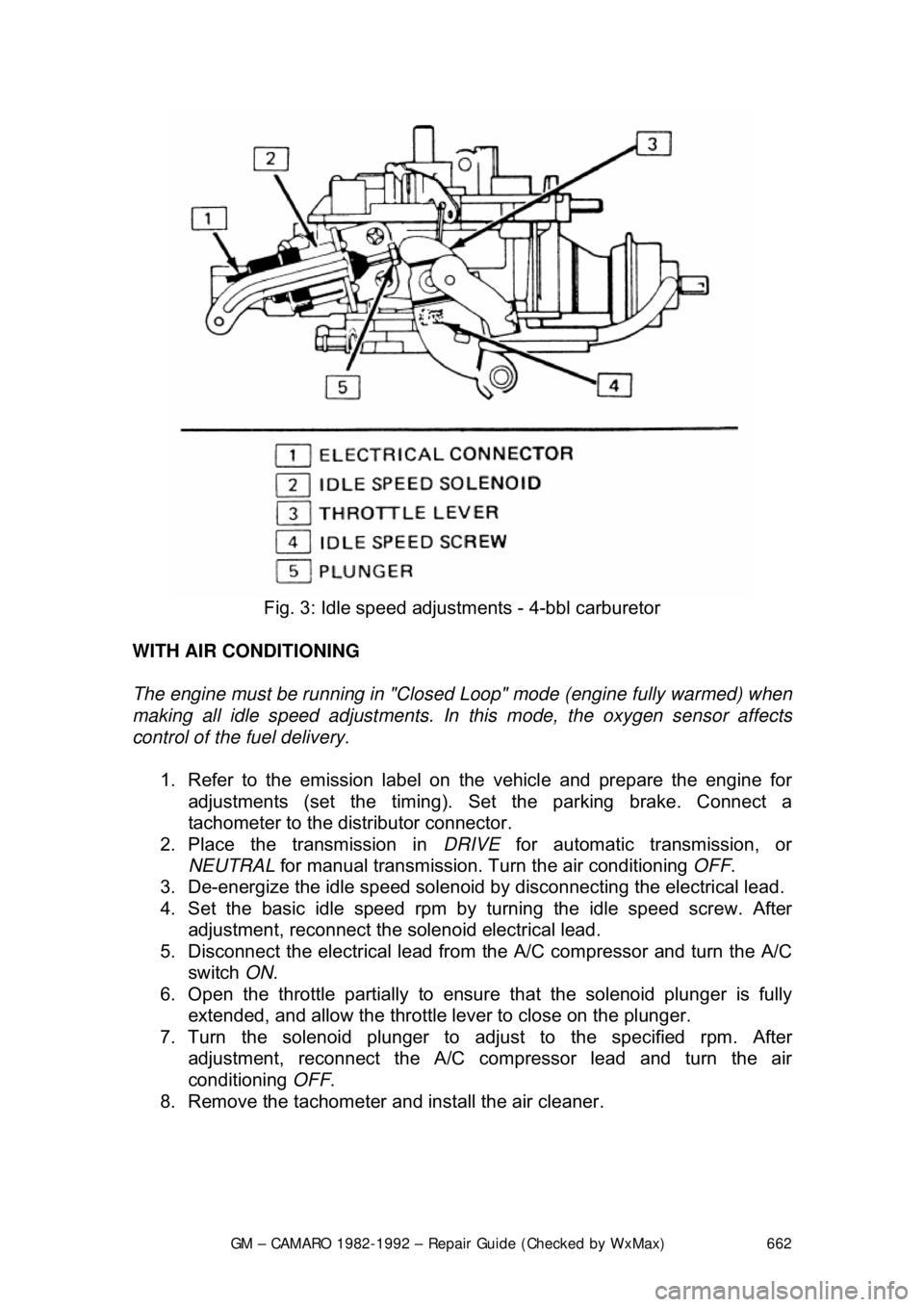
Fig. 3: Idle speed adjustm ents - 4-bbl carburetor
WITH AIR CONDITIONING
The engine must be running in "Closed Loop" mode (engine fully warmed) when
making all idle speed adjustments. In this mode, the oxygen sensor affects
control of the fuel delivery.
1. Refer to the emission label on the vehicle and prepare the engine for
adjustments (set the timing). Se t the parking brake. Connect a
tachometer to the dist ributor connector.
2. Place the transmission in DRIVE for automatic transmission, or
NEUTRAL for manual transmission. Tu rn the air conditioning OFF.
3. De-energize the idle speed solenoid by disconnecting the electrical lead.
4. Set the basic idle speed rpm by turning the idle speed screw. After
adjustment, reconnect the solenoid electrical lead.
5. Disconnect the electrical lead from the A/C compressor and turn the A/C
switch ON.
6. Open the throttle partially to ensure that the solenoid plunger is fully
extended, and allow the throttle lever to close on the plunger.
7. Turn the solenoid plunger to adj ust to the specified rpm. After
adjustment, reconnect the A/C co mpressor lead and turn the air
conditioning OFF.
8. Remove the tachometer and install the air cleaner.
Page 669 of 875

GM – CAMARO 1982-1992 – Repair Guide (Checked by WxMax) 669
1. Disconnect the pressure gauge. R
un the fuel line into a graduated
container.
2. Run the engine at idle until one pint of gasoline has been pumped. One
pint should be delivered in 30 seconds or less. There is normally enough
fuel in the carburetor float bowl to perform this test, but refill it if
necessary.
3. If the delivery rate is below the mini mum, check the lines for restrictions
or leaks, then r eplace the pump.
CARBURETORS
The V6 engine is equipped with the Ro chester E2SE carburetor, V8 engines
use the E4ME and E4MC. These carburet ors are of the downdraft design and
are used in conjunction with the CCC system for fuel cont rol. They have special
design features for optimum air/fuel mixt ure control during all ranges of engine
operation.
An electric solenoid in the carburetor controls the air/fu el ratio. The solenoid is
connected to an Electronic Control Module (ECM) which is an on-board
computer. The ECM provides a controllin g signal to the solenoid. The solenoid
controls the metering rod(s) and an id le air bleed valve, thereby closely
controlling the air/fuel ratio throughout the operating range of the engine.
MODEL IDENTIFICATION
General Motors Rochester carburetors ar e identified by their model code. The
first number indicates the number of ba rrels, while one of the last letters
indicates the type of choke used. These are V for the manifold mounted choke
coil, C for the choke coil mounted in the carburetor body, and E for electric
choke, also mounted on the carburetor. Model codes ending in A indicate an
altitude-compensatin g carburetor.
Because of their intricate nature and co mputer controls, the E2SE, E4ME and
E4MC carburetors should only be se rviced by a qualified technician.
PRELIMINARY CHECKS
The following should be observed befor e attempting any adjustments.
1. Thoroughly warm the engine. If the engine is cold, be sure that it reaches
operating temperature.
2. Check the torque of all carburet or mounting nuts and assembly screws.
Also check the intake manifold-to-cyli nder head bolts. If air is leaking at
any of these points, any attempts at adjustment will inevitably lead to
frustration.
3. Check the manifold heat control valve (if used) to be sure that it is free.
4. Check and adjust the choke as necessary.
5. Adjust the idle speed and mixture. If the mixture screws are capped,
don't adjust them unless all other c auses of rough idle have been
eliminated. If any adjustments are per formed that might possibly change
Page 687 of 875

GM – CAMARO 1982-1992 – Repair Guide (Checked by WxMax) 687
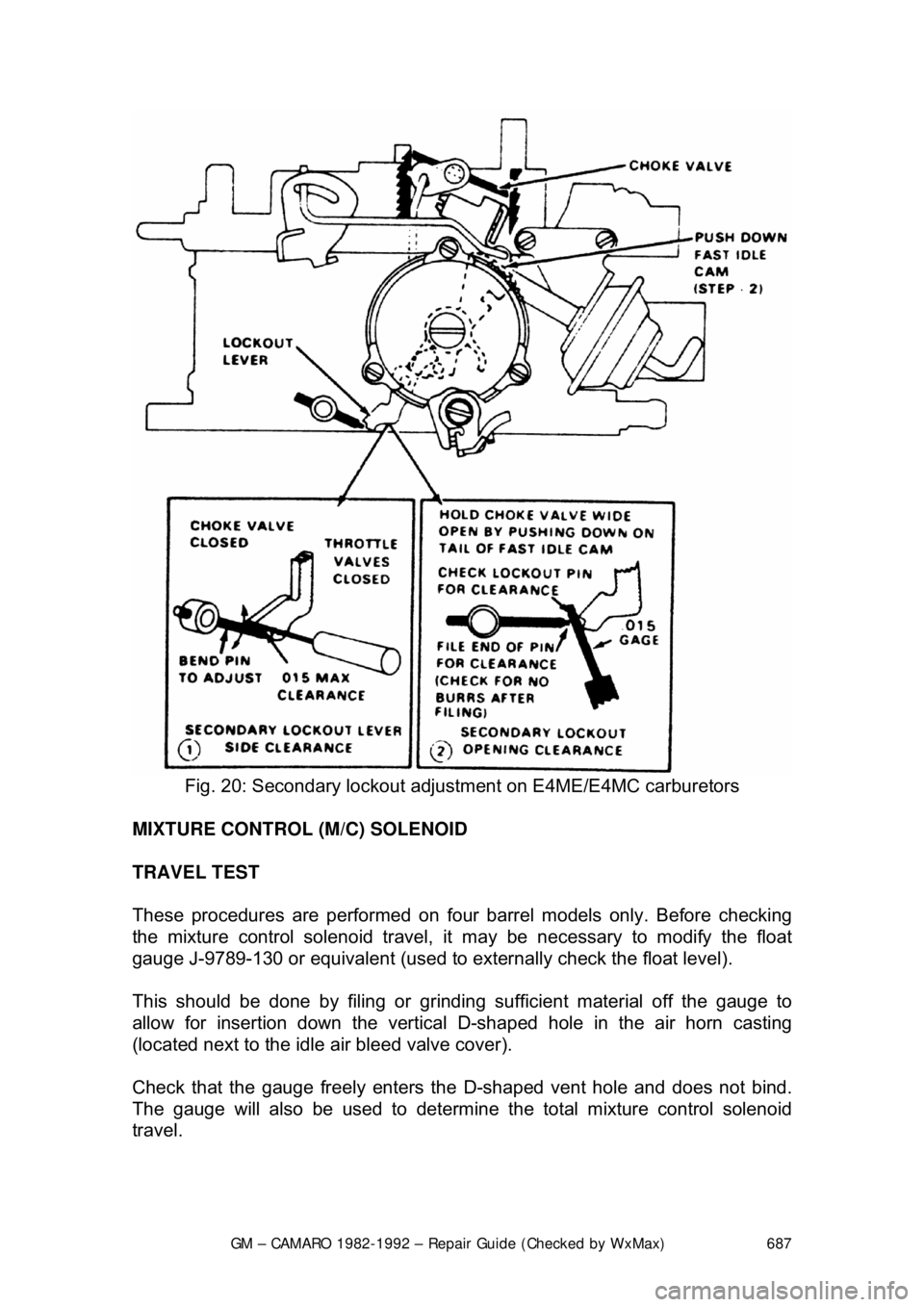
Fig. 20: Secondary lockout adjus tment on E4ME/E4MC carburetors
MIXTURE CONTROL (M/C) SOLENOID
TRAVEL TEST
These procedures are performed on four barrel models only. Before checking
the mixture control solenoid travel, it may be necessary to modify the float
gauge J-9789-130 or equivalent (used to ex ternally check the float level).
This should be done by filing or grinding sufficient material off the gauge to
allow for insertion down the vertical D-shaped hole in the air horn casting
(located next to the idle air bleed valve cover).
Check that the gauge freely enters the D-shaped vent hole and does not bind.
The gauge will also be used to determine t he total mixture control solenoid
travel.
Page 743 of 875

GM – CAMARO 1982-1992 – Repair Guide (Checked by WxMax) 743
MINIMUM IDLE SPEED
The minimum idle speed should onl
y be adjusted under two conditions:
If the throttle body has been replaced.
After every other possible cause for the in correct idle speed has been explored.
There are many possible causes for incorre ct idle speed, most of which require
a high level of diagnostic skill as well as expensive testing equipment. Check
the vehicle for vacuum leaks, incorrect valve or ignition timing, deposit
accumulation in the throttle bore or valve, sticking throttle linkage or bent throttle
valves. If the vehicle will still not idle pr operly after checking these areas, it
should be diagnosed by a professional.
1. Pierce the idle stop screw with an awl. Apply leverage to remove it.
2. Make sure the IAC valve is connect ed. Short the A and B terminals of the
ALDL connector together with a length of wire.
3. Turn the ignition to the ON positi on, but do not start the engine. Wait at
least 30 seconds before proceeding.
4. With the ignition ON, disconnect the IAC valve connector.
5. Separate the set-timing connector. Th is eliminates the possibility of
changes in engine speed due to variations of engine timing.
6. Start the engine and remove t he wire shorting the A and B terminals
together. It may be necessary to hold the throttle open slightly to prevent
the engine from stalling.
7. Allow the engine to reach no rmal operating temperature.
8. Adjust the idle speed to the following: a. 2.8L Engines - 450-550 rp m A/T or 550-650 rpm M/T
b. 3.1L Engines - Refer to the underhood emissions sticker
c. 5.0L and 5.7L TPI engines - 400-450 rpm.
If these figures differ from t hose on the underhood emissions
sticker, always follow the specifications on the emissions sticker.
9. Turn the ignition OFF and connect the IAC valve harness. On models up
to 1989, adjust the Throttle Position Sensor.
THROTTLE POSITION SENSOR (TPS) 1. Install three jumper wires betw een the TPS and the harness connector.
2. Use a digital voltmeter connected to terminals A and B of the TPS.
3. Turn the ignition switch ON , but do not start the engine.
4. Loosen the TPS attaching screws and adj ust the sensor to the following:
a. 2.8L Engines - 0.50-0.60 volts
b. 5.0L and 5.7L TPI Engines - 0.47-0.61 volts
5. Tighten the attaching screws, then check that the reading has not been
disturbed.
6. With the ignition OFF, remove the jumper wires. Reconnect the TPS
harness.
Page 812 of 875

GM – CAMARO 1982-1992 – Repair Guide (Checked by WxMax) 812
9. Connect one end of the other jumper
cable to the negative (-) terminal on
the booster battery and the final cable clamp to an engine bolt head,
alternator bracket or ot her solid, metallic point on the engine with the
dead battery. Try to pick a ground on the engine that is positioned away
from the battery in order to minimi ze the possibility of the 2 clamps
touching should one l oosen during the procedure. DO NOT connect this
clamp to the negative (-) term inal of the bad battery.
CAUTION - Be very careful to keep the jum per cables away from moving parts
(cooling fan, belts, etc.) on both engines.
10. Check to make sure that the c ables are routed away from any moving
parts, then start the d onor vehicle's engine. Run the engine at moderate
speed for several minutes to allow the dead battery a chance to receive
some initial charge.
11. With the donor vehicle's engine still r unning slightly above idle, try to start
the vehicle with the dead battery. Crank the engine for no more than 10 \
seconds at a time and let the starter cool for at least 20 seconds between
tries. If the vehicl e does not start in 3 tries, it is likely that something else
is also wrong or that the battery needs additional time to charge.
12. Once the vehicle is star ted, allow it to run at idle for a few seconds to
make sure that it is operating properly.
13. Turn ON the headlight s, heater blower and, if equipped, the rear
defroster of both vehicles in order to reduce the severity of voltage spikes
and subsequent risk of dam age to the vehicles' electrical systems when
the cables are disconnected. This st ep is especially important to any
vehicle equipped with computer control modules.
14. Carefully disconnect the cables in the reverse order of connection. Star\
t with the negative cable that is attached to the engine ground, then the
negative cable on the donor battery. Di sconnect the positive cable from
the donor battery and finally, disconnect the positive cable from the
formerly dead battery. Be careful when disconnecting the cables from the
positive terminals not to allow the alli gator clips to touch any metal on
either vehicle or a short and sparks will occur.
JACKING
Your vehicle was supplied with a jack for emergency road repairs. This jack is
fine for changing a flat tire or other s hort term procedures not requiring you to
go beneath the vehicle. If it is used in an emergency situation, carefully follow
the instructions provided eit her with the jack or in your owner's manual. Do not
attempt to use the jack on any portions of the vehicle other than specified by the
vehicle manufacturer. Always block the diagonally opposite wheel when using a
jack.
A more convenient way of jacking is the use of a garage or floor jack. You may
use the floor jack to raise the vehicle in the areas shown in the illustration .