1982 CHEVROLET CAMARO check engine
[x] Cancel search: check enginePage 449 of 875

GM – CAMARO 1982-1992 – Repair Guide (Checked by WxMax) 449
1. Remove the intake manifold, valve
cover and pushrod cover (4-cylinder).
Disassemble the rocker arms and remove the pushrods.
2. Remove the lifters. If they are coat ed with varnish, clean with carburetor
cleaning solvent.
3. If installing new lifters or you have disassembled the lifters, they must be
primed before installation. Submer ge the lifters in SAE 10 oil and
carefully push down on the plunger with a
1/8 in. (3mm) drift. Hold the
plunger down (DO NOT pum p), then release the plunger slowly. The lifter
is now primed.
4. Coat the bottoms of the lifters wit h Molykote® before installation. Install
the lifters and pushrods into the e ngine in their original position.
5. Install the rocker arms and adjust the valves. Complete the installation by
reversing the removal procedure.
FREEZE PLUGS
REMOVAL & INSTALLATION
CAUTION - When draining the coolant, keep in mind that cats and dogs are
attracted by the ethylene gl ycol antifreeze, and are quite likely to drink any that
is left in an uncovered container or in puddles on the ground. This will prove
fatal in sufficient quantity. Always drai n the coolant into a sealable container.
Coolant should be reused unless it is contaminated or several years old.
1. Disconnect the negative battery cable.
2. Drain the cooling system.
3. Raise and support the vehicle safely.
4. Remove the coolant drain plug on t he side of the block, if equipped. If not
you can use a punch to put a small ho le in the center of the freeze plug
that is being replaced.
5. Remove all components in order to gain access to the freeze plug(s).
6. Using a punch, tap the bottom corner of the freeze plug to cock it in the
bore. Remove the plug using pliers.
7. Clean the freeze plug hole and c oat the new plug with sealer.
8. Using a suitable tool, install the freeze plug into the block.
9. Connect the negative battery cable, fill the cooling system, start the
engine and check for leaks.
REAR MAIN OIL SEAL
REMOVAL & INSTALLATION
CAUTION - The EPA warns that prol onged contact with used engine oil may
cause a number of skin disorders, incl uding cancer! You should make every
effort to minimize your exposure to used engine oil. Pr otective gloves should be
worn when changing the oil. Wash y our hands and any other exposed skin
areas as soon as possible after exposure to used engine oil. Soap and water, or
waterless hand cleaner should be used.
1-PIECE NEOPRENE SEAL
Page 451 of 875
GM – CAMARO 1982-1992 – Repair Guide (Checked by WxMax) 451
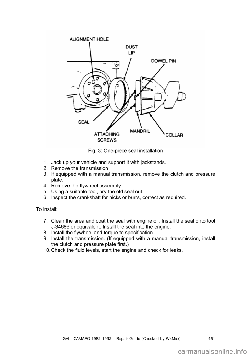
Fig. 3: One-piece seal installation
1. Jack up your vehicle and support it with jackstands.
2. Remove the transmission.
3. If equipped with a manual transmission, remove the clutch and pressure
plate.
4. Remove the flywheel assembly.
5. Using a suitable tool, pry the old seal out.
6. Inspect the crankshaft for nicks or burrs, correct as required.
To install: 7. Clean the area and coat the seal with eng ine oil. Install the seal onto tool
J-34686 or equivalent. Install the seal into the engine.
8. Install the flywheel and torque to specification.
9. Install the transmission. (If equipped with a manual transmission, install
the clutch and pressure plate first.)
10. Check the fluid levels, star t the engine and check for leaks.
Page 453 of 875
GM – CAMARO 1982-1992 – Repair Guide (Checked by WxMax) 453
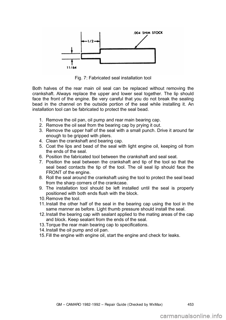
Fig. 7: Fabricated s eal installation tool
Both halves of the rear main oil s eal can be replaced without removing the
crankshaft. Always replace the upper and lower seal together. The lip should
face the front of the engine. Be very ca reful that you do not break the sealing
bead in the channel on the out side portion of the seal while installing it. An
installation tool can be fabricat ed to protect the seal bead.
1. Remove the oil pan, oil pump and rear main bearing cap.
2. Remove the oil seal from the bearing cap by prying it out.
3. Remove the upper half of the seal wit h a small punch. Drive it around far
enough to be gripped with pliers.
4. Clean the crankshaft and bearing cap.
5. Coat the lips and bead of the seal with light engine oil, keeping oil from
the ends of the seal.
6. Position the fabricated tool bet ween the crankshaft and seal seat.
7. Position the seal between the cranks haft and tip of the tool so that the
seal bead contacts the ti p of the tool. The oil seal lip should face the
FRONT of the engine.
8. Roll the seal around the crankshaft us ing the tool to protect the seal bead
from the sharp corner s of the crankcase.
9. The installation tool should be le ft installed until the seal is properly
positioned with both ends fl ush with the block.
10. Remove the tool.
11. Install the other half of the seal in the bearing cap using the tool in the
same manner as before. Light thumb pressure should install the seal.
12. Install the bearing cap with sealant applied to the mating areas of the cap
and block. Keep sealant from the ends of the seal.
13. Torque the rear main bear ing cap to specifications.
14. Install the oil pump and oil pan.
15. Fill the engine with engine oil, st art the engine and check for leaks.
Page 455 of 875
GM – CAMARO 1982-1992 – Repair Guide (Checked by WxMax) 455
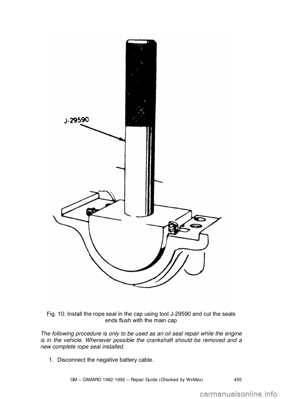
Fig. 10: Install the rope seal in the cap using tool J-29590 and cut the seals
ends flush with the main cap
The following procedure is only to be used as an oil seal repair while the engine
is in the vehicle. Whenever possible the crankshaft should be removed and a
new complete rope seal installed.
1. Disconnect the negative battery cable.
Page 456 of 875

GM – CAMARO 1982-1992 – Repair Guide (Checked by WxMax) 456
2. Drain the engine oil and remove the oil pan.
3. Remove the rear main bearing cap.
4. Insert packing tool J-29114-2 or equi
valent, against 1 end of the seal in
the cylinder block. Drive the old seal gently into the groove until it is
packed tight. This will vary from
1/4 in. (6mm) to 3/4 in. (19mm) depending
on the amount of pack required.
5. Repeat the procedure on t he other end of the seal.
6. Measure the amount the seal wa s driven up on one side and add
1/16 in.
(1.6mm). Using a suitable cutting tool, cut that length from the old seal
removed from the rear main beari ng cap. Repeat the procedure for the
other side. Use the rear main bear ing cap as a holding fixture when
cutting the seal.
7. Install guide tool J-29114-1 or equi valent, onto the cylinder block.
8. Using the packing tool, work the shor t pieces cut in Step 6 into the guide
tool and then pack into the cylinder block. The guide tool and packing
tool are machined to provide a built in stop. Use this procedure for both
sides. It may help to use oil on the short pieces of the rope seal when \
packing them into the cylinder block.
9. Remove the guide tool.
10. Apply Loctite® 414 or equivalent, to the seal groove in the rear main
bearing cap. Within 1 minute, insert a new seal into the groove and push
into place with tool J-29590 until the seal is flush with the block. Cut the
excess seal material with a sharp cu tting tool at the bearing cap parting
line.
11. Apply a thin film of chassis grease to the rope se al. Apply a thin film of
RTV sealant on the bearing cap mati ng surface around the seal groove.
Use the sealer sparingly.
12. Plastigage® the rear main bea ring cap as outlined in MEASURING
REAR MAIN CLEARANCE in this section and check with specification. If
out of specification, check for fr ying of the rope seal which may be
causing the cap to not seat properly.
13. Install all remaining com ponents and inspect for leaks.
FLYWHEEL AND RING GEAR
REMOVAL & INSTALLATION
The ring gear is an integral part of the flywheel and is not replaceable.
1. Remove the transmission.
2. Remove the six bolts attaching t he flywheel to the crankshaft flange.
Remove the flywheel.
3. Inspect the flywheel for cracks, and inspect the ring gear for burrs or
worn teeth. Replace the flywheel if any damage is apparent. Remove
burrs with a mill file.
4. Install the flywheel. Th e flywheel will only attach to the crankshaft in one
position, as the bolt holes are unevenly spaced. Install the bolts and
torque to specification. Tighten bolts in crisscross pattern.
Page 457 of 875
GM – CAMARO 1982-1992 – Repair Guide (Checked by WxMax) 457
EXHAUST SYSTEM
INSPECTION
Safety glasses should be worn at all
times when working on or near the exhaust
system. Older exhaust systems will almost always be covered with loose rust
particles which will shower you when dist urbed. These particles are more than a
nuisance and could injure your eye.
CAUTION - Do NOT perform exhaust repairs or inspection with the engine or
exhaust hot. Allow the system to cool completely before attempting any work.
Exhaust systems are noted for sharp edges , flaking metal and rusted bolts.
Gloves and eye protection ar e required. A healthy supply of penetrating oil and
rags is highly recommended.
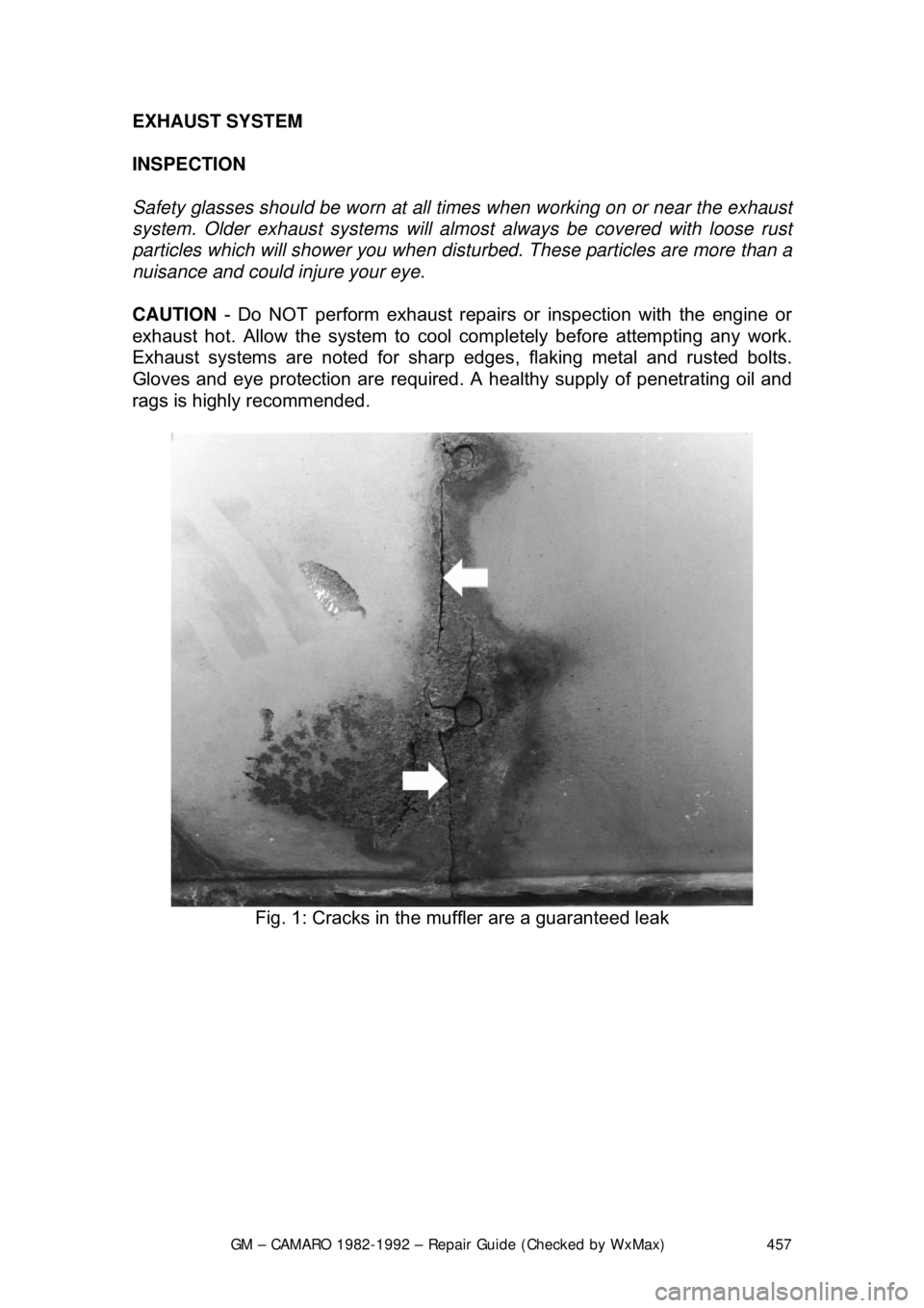
Fig. 1: Cracks in the mu ffler are a guaranteed leak
Page 462 of 875
GM – CAMARO 1982-1992 – Repair Guide (Checked by WxMax) 462
REPLACEMENT
There are basically two types of exhaust sy
stems. One is the flange type where
the component ends are attached with bolts and a gasket in-between. The other
exhaust system is the slip joint type. These components slip into one another
using clamps to retain them together.
CAUTION - Allow the exhaust system to c ool sufficiently before spraying a
solvent exhaust fasteners. Some solvents are highly flammable and could ignite
when sprayed on hot exhaust components.
Before removing any component of the ex haust system, ALWAYS squirt a liquid
rust dissolving agent onto the fasteners fo r ease of removal. A lot of knuckle
skin will be saved by following this rule. It may even be wise to spray the
fasteners and allow them to sit overnight.
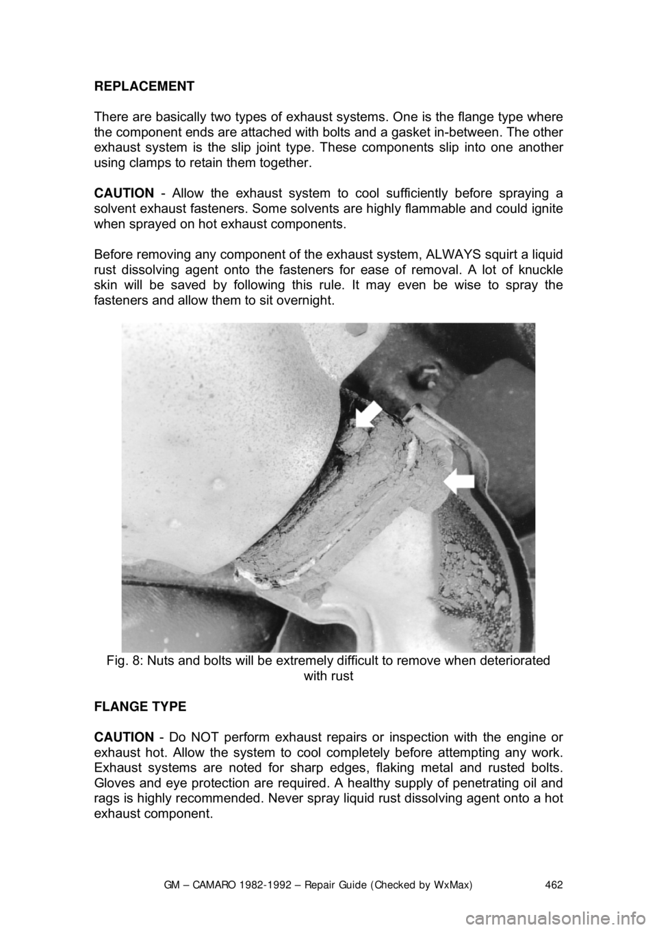
Fig. 8: Nuts and bolts will be extremely difficult to remove when deteriorated
with rust
FLANGE TYPE
CAUTION - Do NOT perform exhaust repairs or inspection with the engine or
exhaust hot. Allow the system to cool completely before attempting any work.
Exhaust systems are noted for sharp edges , flaking metal and rusted bolts.
Gloves and eye protection ar e required. A healthy supply of penetrating oil and
rags is highly recommended. Never spra y liquid rust dissolving agent onto a hot
exhaust component.
Page 465 of 875

GM – CAMARO 1982-1992 – Repair Guide (Checked by WxMax) 465
Fig. 12: Muffler hanger attachment
ENGINE RECONDITIONING DETE RMINING ENGINE CONDITION
Anything that generates heat and/or friction will eventually burn or wear out (i.e.
a light bulb generates heat, therefore its life span is limited). With this in mind, a
running engine generates trem endous amounts of both; friction is encountered
by the moving and rotating parts inside the engine and heat is created b\
y
friction and combustion of the fuel. Ho wever, the engine has systems designed
to help reduce the effects of heat and fr iction and provide added longevity. The
oiling system reduces the amount of fr iction encountered by the moving parts
inside the engine, while the cooling system reduces heat created by friction and
combustion. If either system is not main tained, a break-down will be inevitable.
Therefore, you can see how regular main tenance can affect the service life of
your vehicle. If you do not drain, flush and refill your cooling system at the
proper intervals, deposits will begin to accumulate in the radiator, thereby
reducing the amount of heat it can extrac t from the coolant. The same applies to
your oil and filter; if it is not changed often enoug h it becomes laden with
contaminates and is unable to properly lubricate the engine. This increases
friction and wear.
There are a number of methods for evaluat ing the condition of your engine. A
compression test can reveal the condition of your pistons, piston rings, cylinder
bores, head gasket(s), valves and valve seat s. An oil pressure test can warn
you of possible engine bearing, or oil pump failures. Excessive oil consumption,
evidence of oil in the engine air intake area and/or bluish smoke from the tail
pipe may indicate worn piston rings, worn valve guides and/or valve seals. As a
general rule, an engine that uses no more than one quart of oil every 1000
miles is in good condi tion. Engines that use one quart of oil or more in less than
1000 miles should first be checked for oil leaks. If any oil leaks are present,
have them fixed before dete rmining how much oil is consumed by the engine,
especially if blue smoke is not visible at the tail pipe.
COMPRESSION TEST
A noticeable lack of engine power, excessive oil consumption and/or poor fuel
mileage measured over an extended period are all indicators of internal engine