1982 CHEVROLET CAMARO check engine
[x] Cancel search: check enginePage 498 of 875

GM – CAMARO 1982-1992 – Repair Guide (Checked by WxMax) 498
3. Measure the gauge with the microm
eter and record the reading.
4. Again, hold the gauge square in t he bore, this time parallel to the
crankshaft centerline, and ge ntly tighten the lock. Again, you will tilt the
gauge back to remove it from the bore.
5. Measure the gaug e with the micrometer and record this reading. The
difference between these two readings is the out-of-round measurement
of the cylinder.
6. Repeat steps 1 through 5, each time going to the next lower position,
until you reach the bottom of the cyli nder. Then go to the next cylinder,
and continue until all of the cylinders have been measured.
The difference between these measurements will tell you all about the wear in
your cylinders. The measurements whic h were taken 90 degrees from the
crankshaft centerline will always reflect t he most wear. That is because at this
position is where the engine power presses the piston against the cylinder bore
the hardest. This is known as thrust wear. Take your top, 90 degree
measurement and compare it to your bottom, 90 degree measurement. The
difference between them is the taper. W hen you measure your pistons, you will
compare these readings to your pist on sizes and determine piston-to-wall
clearance.
CRANKSHAFT
Inspect the crankshaft for visible signs of wear or damage. All of the journals
should be perfectly round and smooth. Slight scores are normal for a used
crankshaft, but you should hardly feel them with your fingernail. When
measuring the crankshaft wit h a micrometer, you will take readings at the front
and rear of each journal, then turn t he micrometer 90 degrees and take two
more readings, front and rear. The differ ence between the front-to-rear readings
is the journal taper and the first-to -90 degree reading is the out-of-round
measurement. Generally, there should be no taper or out-of-roundness found,
however, up to 0.0005 in. (0.0127mm) fo r either can be overlooked. Also, the
readings should fall within the factory s pecifications for journal diameters.
If the crankshaft journals fall within specif ications, it is recommended that it be
polished before being returned to service. Polishing the crankshaft insures that
any minor burrs or high spots are smoot hed, thereby reducing the chance of
scoring the new bearings.
PISTONS AND CONNECTING RODS
PISTONS
The piston should be visually inspect ed for any signs of cracking or burning
(caused by hot spots or detonation), and scuffing or excessive wear on the
skirts. The wristpin attaches the piston to the connecting rod. The piston should
move freely on the wrist pin, both sliding and pivoting. Grasp the connecting rod
securely, or mount it in a vise, and tr y to rock the piston back and forth along
the centerline of t he wristpin. There should not be any excessive play evident
between the piston and the pin. If there are C-clips retaining the pin in the piston
Page 500 of 875

GM – CAMARO 1982-1992 – Repair Guide (Checked by WxMax) 500
within specifications, install new bear
ings in the rod and take another
measurement. If the clearance is still out of specifications, and the crankshaft is
not, the rod will need to be reconditioned by a machine shop.
You can also use Plastigage to check the bearing clearances. The assembling
section has complete instructions on its use.
CAMSHAFT
Inspect the camshaft and lifters/followers as described earlier in this section.
BEARINGS
All of the engine bearings should be visua lly inspected for wear and/or damage.
The bearing should look evenly worn a ll around with no deep scores or pits. If
the bearing is severely worn, scored, pi tted or heat blued, then the bearing, and
the components that use it, should be brought to a machine shop for inspection.
Full-circle bearings (used on most camshafts, auxiliary shafts, balance shafts,
etc.) require specialized tools for re moval and installation, and should be
brought to a machine shop for service.
OIL PUMP
The oil pump is responsible for provid ing constant lubrication to the whole
engine and so it is re commended that a new oil pump be installed when
rebuilding the engine.
Completely disassemble the oil pump and thoroughly clean all of the
components. Inspect the oil pump gears and housing for wear and/or damage.
Insure that the pressure relief valve oper ates properly and there is no binding or
sticking due to varnish or debris. If all of the parts are in proper working
condition, lubricate the gears and relie f valve, and assemble the pump.
REFINISHING
Almost all engine block refinishing must be performed by a machine shop. If the
cylinders are not to be rebored, then t he cylinder glaze can be removed with a
ball hone. When removing cylinder glaz e with a ball hone, use a light or
penetrating type oil to lubricate the hone. Do not allow the hone to run dry as
this may cause excessive scoring of t he cylinder bores and wear on the hone. If
new pistons are required, t hey will need to be installed to the connecting rods.
This should be performed by a machine shop as the pistons must be installed in
the correct relationship to the rod or engine damage can occur.
Page 501 of 875

GM – CAMARO 1982-1992 – Repair Guide (Checked by WxMax) 501
Fig. 5: Use a ball type cylinder hone to remove any glaze and provide a new
surface for seating the piston rings
PISTONS AND CONNECTING RODS
Only pistons with the wrist pin retained by C-clips are serviceable by the home-
mechanic. Press fit pistons require special presses and/or heaters to
remove/install the connecting rod and sh ould only be performed by a machine
shop.
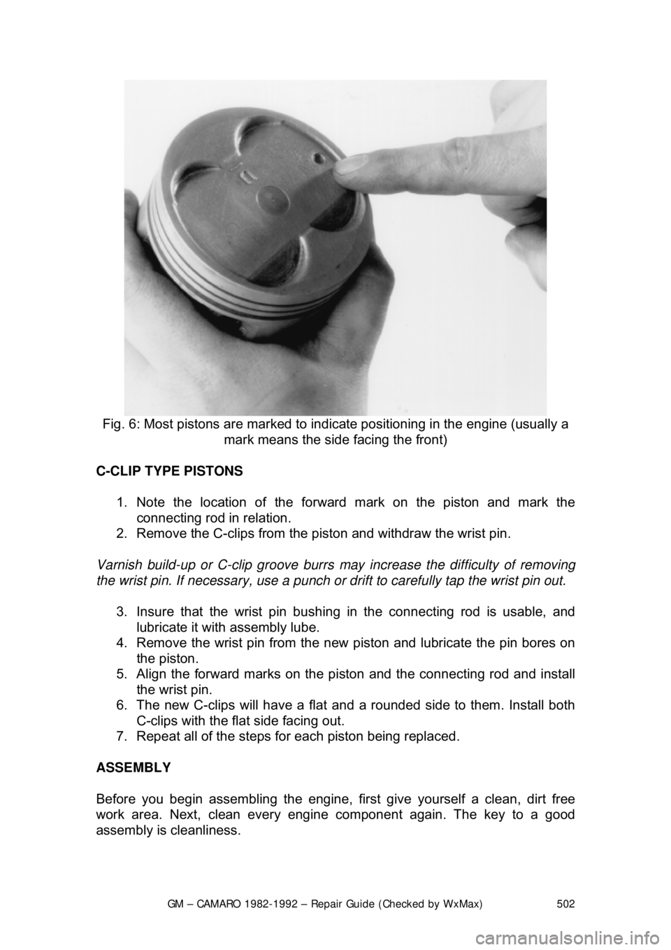
All pistons will have a mark indicating the direction to the front of the engine and
the must be installed into the engine in that manner. Usually it is a notch or
arrow on the top of the piston, or it ma y be the letter F cast or stamped into the
piston.
Page 502 of 875

GM – CAMARO 1982-1992 – Repair Guide (Checked by WxMax) 502
Fig. 6: Most pistons are marked to indica te positioning in the engine (usually a
mark means the side facing the front)
C-CLIP TYPE PISTONS 1. Note the location of the forward mark on the piston and mark the connecting rod in relation.
2. Remove the C-clips from the piston and withdraw the wrist pin.
Varnish build-up or C-clip groove burrs may increase the difficulty of removing
the wrist pin. If necessary, use a punch or drift to carefully tap the wrist pin out.
3. Insure that the wrist pin bushing in the connecting rod is usable, and
lubricate it with assembly lube.
4. Remove the wrist pin from the new piston and lubricate the pin bores on
the piston.
5. Align the forward marks on the pi ston and the connecting rod and install
the wrist pin.
6. The new C-clips will have a flat and a rounded side to them. Install both
C-clips with the flat side facing out.
7. Repeat all of the steps fo r each piston being replaced.
ASSEMBLY
Before you begin assembling the engine, fi rst give yourself a clean, dirt free
work area. Next, clean every engine component again. The key to a good
assembly is cleanliness.
Page 503 of 875

GM – CAMARO 1982-1992 – Repair Guide (Checked by WxMax) 503
Mount the engine block into the engine
stand and wash it one last time using
water and detergent (dishwashing deter gent works well). While washing it,
scrub the cylinder bores with a soft bristl e brush and thoroughly clean all of the
oil passages. Completely dry the engin e and spray the entire assembly down
with an anti-rust solution such as WD-40 or similar product. Take a clean lint-
free rag and wipe up any excess anti-rust solution from the bores, bearing
saddles, etc. Repeat the final cleaning process on the crankshaft. Replace any
freeze or oil galley plugs which we re removed during disassembly.
CRANKSHAFT 1. Remove the main bearing inserts from the block and bearing caps.
2. If the crankshaft main bearing journal s have been refinished to a definite
undersize, install the correct undersize bearing. Be sure that the bearing
inserts and bearing bores are clean. Fo reign material under inserts will
distort bearing and cause failure.
3. Place the upper main bearing inse rts in bores with tang in slot.
The oil holes in the beari ng inserts must be aligned with the oil holes in the
cylinder block.
4. Install the lower main bearing inserts in bearing caps.
5. Clean the mating surfaces of block and rear main bearing cap.
6. Carefully lower the crankshaft into place. Be careful not to damage
bearing surfaces.
7. Check the clearance of each main bearing by using the following
procedure: a. Place a piece of Plastigage® or its equivalent, on bearing surface
across full width of bearing cap and about
1/4 in. off center.
Page 505 of 875

GM – CAMARO 1982-1992 – Repair Guide (Checked by WxMax) 505
b. Install cap and tighten bolts to spec
ifications. Do not turn crankshaft
while Plastigage® is in place.
c. Remove the cap. Using the supplie d Plastigage® scale, check width of
Plastigage® at widest point to get maximum clearance. Difference
between readings is ta per of journal.
Fig. 8: After the cap is removed again, use the sca le supplied with the gauging
material to check the clearance
d. If clearance exceeds specified lim its, try a 0.001 in. or 0.002 in.
undersize bearing in combination with the standard bearing. Bearing
clearance must be within specified limits. If standard and 0.002 in.
undersize bearing does not bring clearance within desired limits, refinish
crankshaft journal, then inst all undersize bearings.
5. If equipped with a rope or two-piece r ear main seal, Install it now.
6. After the bearings have been fitted, apply a light coat of engine oil to the
journals and bearings. Install the rear main bearing cap. Install all
bearing caps except the thrust bearing cap. Be sure that main bearing
caps are installed in original locati ons. Tighten the bearing cap bolts to
specifications.
7. Install the thrust bearing cap with bolts finger-tight.
8. Pry the crankshaft forward against the thrust surface of upper half of
bearing.
9. Hold the crankshaft forward and pry the thrust bearing cap to the rear.
This aligns the thrust surfaces of both halves of the bearing.
10. Retain the forward pressure on t he crankshaft. Tighten the cap bolts to
specifications.
Page 506 of 875

GM – CAMARO 1982-1992 – Repair Guide (Checked by WxMax) 506
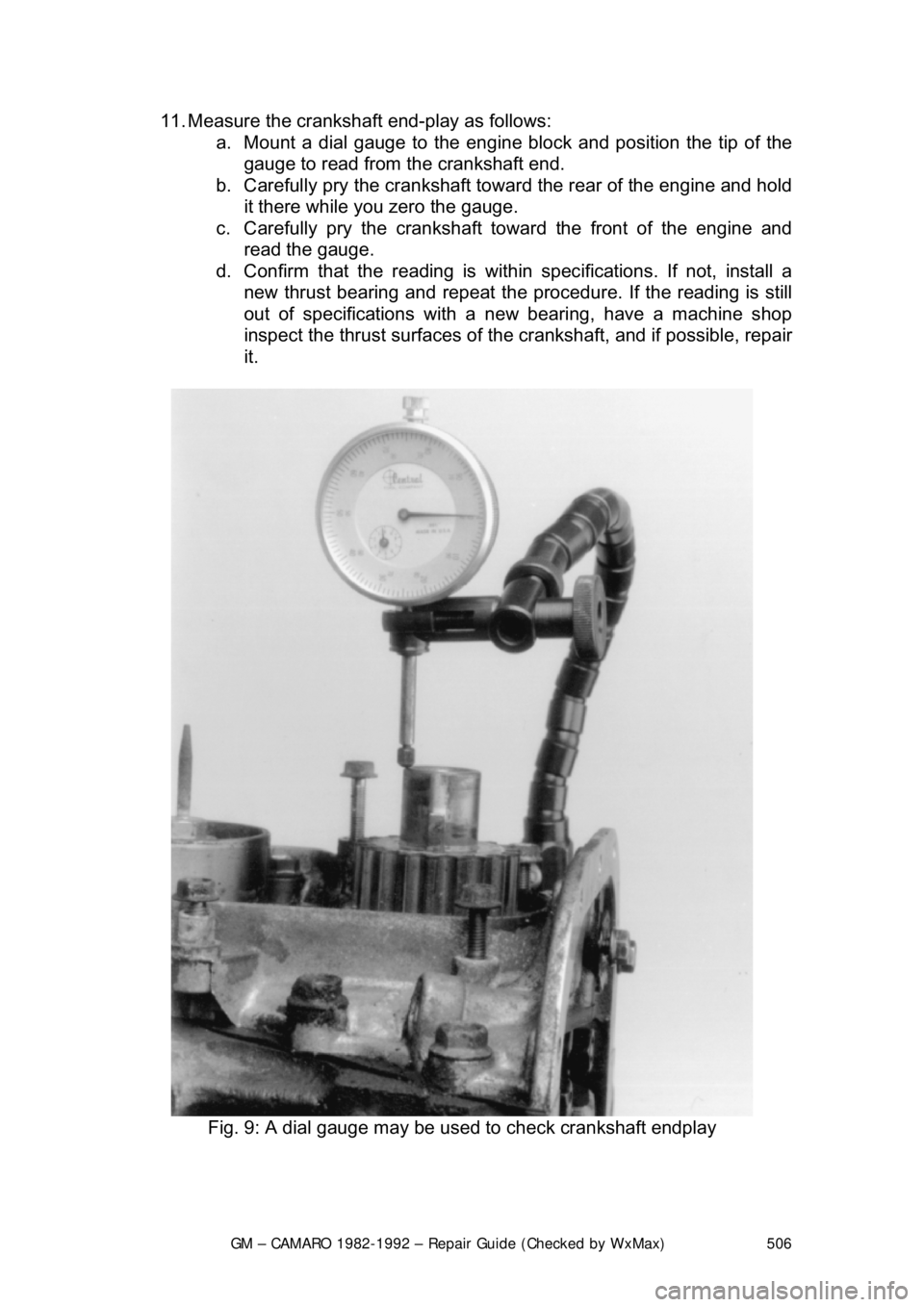
11. Measure the crankshaft end-play as follows:
a. Mount a dial gauge to the engine block and position the tip of the
gauge to read from t he crankshaft end.
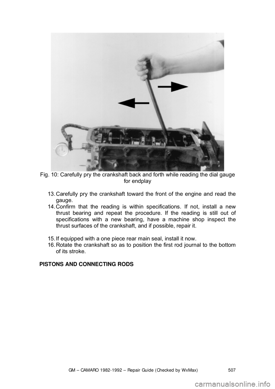
b. Carefully pry the crankshaft towa rd the rear of the engine and hold
it there while you zero the gauge.
c. Carefully pry the crankshaft toward the front of the engine and read the gauge.
d. Confirm that the r eading is within specifications. If not, install a
new thrust bearing and repeat the procedure. If the reading is still
out of specifications with a new bearing, have a machine shop
inspect the thrust surfaces of the crankshaft, and if possible, repair
it.
Fig. 9: A dial gauge may be used to check crankshaft endplay
Page 507 of 875

GM – CAMARO 1982-1992 – Repair Guide (Checked by WxMax) 507
Fig. 10: Carefully pry the crankshaft back and forth while reading the dial gauge
for endplay
13. Carefully pry the crankshaft toward the front of the engine and read the
gauge.
14. Confirm that the reading is within specifications. If not, install a new
thrust bearing and repeat the procedure. If the readi ng is still out of
specifications with a new bearing, have a machine shop inspect the
thrust surfaces of the cranks haft, and if possible, repair it.
15. If equipped with a one piece rear main seal, install it now.
16. Rotate the crankshaft so as to posi tion the first rod journal to the bottom
of its stroke.
PISTONS AND CONNECTING RODS