1982 CHEVROLET CAMARO engine oil
[x] Cancel search: engine oilPage 653 of 875

GM – CAMARO 1982-1992 – Repair Guide (Checked by WxMax) 653
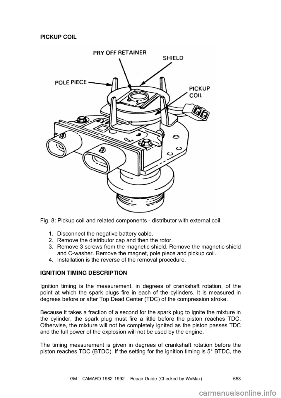
PICKUP COIL
Fig. 8: Pickup coil and related component s - distributor with external coil
1. Disconnect the negative battery cable.
2. Remove the distributor cap and then the rotor.
3. Remove 3 screws from the magnetic shield. Remove the magnetic shield
and C-washer. Remove the magnet, pole piece and pickup coil.
4. Installation is the revers e of the removal procedure.
IGNITION TIMING DESCRIPTION
Ignition timing is the measurement, in de grees of crankshaft rotation, of the
point at which the spark plugs fire in eac h of the cylinders. It is measured in
degrees before or after Top Dead Center (TDC) of the compression stroke.
Because it takes a fraction of a second for the spark plug to ignite the mixture in
the cylinder, the spark plug must fire a little before the piston reaches TDC.
Otherwise, the mixture will not be complete ly ignited as the piston passes TDC
and the full power of the explosion will not be used by the engine.
The timing measurement is given in degr ees of crankshaft rotation before the
piston reaches TDC (BTDC). If the setting fo r the ignition timing is 5° BTDC, the
Page 654 of 875

GM – CAMARO 1982-1992 – Repair Guide (Checked by WxMax) 654
spark plug must fire 5° before each pist
on reaches TDC. This only holds true,
however, when the engine is at idle speed.
As the engine speed increases, the pist ons go faster. The spark plugs have to
ignite the fuel even sooner if it is to be completely ignited when the piston
reaches TDC.
If the ignition is set too far advanced (B TDC), the ignition and expansion of the
fuel in the cylinder will occu r too soon and try to force the piston down while it is
still traveling up. This causes engine ping. If the ignition spark is set too far
retarded, after TDC (ATDC), the pi ston will have already passed TDC and
started on its way down when the fuel is igni ted. This will cause the piston to be
forced down for only a portion of its trav el, resulting in poor engine performance
and lack of power.
When timing the engine, the Number 1 pl ug wire should be used to trigger the
timing light. On engines where timing is adjustable, the notch for the No. 1
cylinder is usually scribed across all th ree edges of the double sheaf pulley.
Another notch located 180° away from t he No. 1 cylinder notch is scribed only
across the center section of the pulley to make it distinguishable from the No. 1
cylinder notch.
There are two basic types of timing light s available. The first type of light
operates from the car's battery. Two al ligator clips connect to the battery
terminals, while a third wire connects to the spark plug with an adapter or to the
spark plug wire with an inductive pickup. This type of light is more expensive,
but the xenon bulb provides a nice bright flash which can even be seen in
sunlight. The second type replaces the battery source with 110-volt house
current. Some timing lights have other func tions built into them, such as dwell
meters, tachometers, or re mote starting switches. These are convenient, in that
they reduce the tangle of wires under t he hood, but may duplicate the functions
of tools you already have.
Because this car uses electronic ignition, you should use a timing light with an
inductive pickup. This pickup simply cl amps around the Number 1 spark plug
wire (in this case, the coil wire), elimin ating the adapter. It is not susceptible to
crossfiring or false triggering, which ma y occur with a conventional light due to
the greater voltages produc ed by these systems.
ADJUSTMENT
When adjusting the timing, refer to the instructions on the emission control
sticker inside the engine compartment. If th e instructions on the label disagree
with the procedure listed below, follo w the instructions on the label.
1982-87 VEHICLES 1. Locate the timing marks on the cran kshaft pulley and the front of the
engine.
Page 669 of 875

GM – CAMARO 1982-1992 – Repair Guide (Checked by WxMax) 669
1. Disconnect the pressure gauge. R
un the fuel line into a graduated
container.
2. Run the engine at idle until one pint of gasoline has been pumped. One
pint should be delivered in 30 seconds or less. There is normally enough
fuel in the carburetor float bowl to perform this test, but refill it if
necessary.
3. If the delivery rate is below the mini mum, check the lines for restrictions
or leaks, then r eplace the pump.
CARBURETORS
The V6 engine is equipped with the Ro chester E2SE carburetor, V8 engines
use the E4ME and E4MC. These carburet ors are of the downdraft design and
are used in conjunction with the CCC system for fuel cont rol. They have special
design features for optimum air/fuel mixt ure control during all ranges of engine
operation.
An electric solenoid in the carburetor controls the air/fu el ratio. The solenoid is
connected to an Electronic Control Module (ECM) which is an on-board
computer. The ECM provides a controllin g signal to the solenoid. The solenoid
controls the metering rod(s) and an id le air bleed valve, thereby closely
controlling the air/fuel ratio throughout the operating range of the engine.
MODEL IDENTIFICATION
General Motors Rochester carburetors ar e identified by their model code. The
first number indicates the number of ba rrels, while one of the last letters
indicates the type of choke used. These are V for the manifold mounted choke
coil, C for the choke coil mounted in the carburetor body, and E for electric
choke, also mounted on the carburetor. Model codes ending in A indicate an
altitude-compensatin g carburetor.
Because of their intricate nature and co mputer controls, the E2SE, E4ME and
E4MC carburetors should only be se rviced by a qualified technician.
PRELIMINARY CHECKS
The following should be observed befor e attempting any adjustments.
1. Thoroughly warm the engine. If the engine is cold, be sure that it reaches
operating temperature.
2. Check the torque of all carburet or mounting nuts and assembly screws.
Also check the intake manifold-to-cyli nder head bolts. If air is leaking at
any of these points, any attempts at adjustment will inevitably lead to
frustration.
3. Check the manifold heat control valve (if used) to be sure that it is free.
4. Check and adjust the choke as necessary.
5. Adjust the idle speed and mixture. If the mixture screws are capped,
don't adjust them unless all other c auses of rough idle have been
eliminated. If any adjustments are per formed that might possibly change
Page 719 of 875

GM – CAMARO 1982-1992 – Repair Guide (Checked by WxMax) 719
11. Lubricate the new large O-ring with cl
ean engine oil and install it directly
over the backup washer. Be sure t he O-ring is seated properly and is
flush with the top of the fuel meter body surface.
12. Lubricate the new small O-ring with clean engine oil and install it on the
nozzle end of the injector. Push t he O-ring on far enough to contact the
filter.
WARNING - Do not attempt to reverse this procedure and install the backup
washer and O-ring after the injector is located in the cavity. To do so will
prevent proper seating of the O-ring in th e cavity recess which could result in a
fuel leak and possible fire.
13. Install the injector by aligning the raised lug on the injector base with the
notch cast into the fuel meter body . Push down on the injector making
sure it is fully seated in the cavity. In jector installation is correct when the
lug is seated in the notch and the electrical terminals are parallel to the
throttle shaft.
14. Using new gaskets on the fuel mete r cover and a new dust seal, install
the cover to the fuel meter body. Use an appropriate thread locking
compound on the cover attaching screws.
15. Connect the injector electrical c onnector by pushing straight down until
seated firmly in place.
16. Connect the negative battery cable.
17. With the engine OFF and the igniti on ON, check for fuel leaks.
18. Install the air cleaner.
ADJUSTMENTS
MINIMUM IDLE SPEED
Minimum idle speed should only be adjus ted when installing a replacement
throttle body. The idle stop screw is used to regulate the minimum idle speed of
the engine. The throttle body is adjusted at the factory, then covered with a cap
or plug to discourage unnecessary readjustment.
2.5L ENGINES 1. Remove the air cleaner and pl ug the THERMAC vacuum port.
2. Disconnect the TV cable from the th rottle control bracket to allow access
to the idle adjustment screw.
3. Remove the throttle stop screw plug or cap.
4. Connect a tachometer to the engine.
5. Disconnect the Idle Air Control (IAC) valve connector.
6. Start the engine with the transmi ssion in PARK (auto transmission) or
NEUTRAL (manual transmission) and allow the engine speed to
stabilize. All accessories (A/C, rear defogger, etc.) should be OFF.
7. Install tool J-33047 in t he idle air passage of the throttle body. Be certain
that the tool seats fully in t he passage and no air leaks exist.
Page 744 of 875

GM – CAMARO 1982-1992 – Repair Guide (Checked by WxMax) 744
7. Start the engine and che
ck for proper operation.
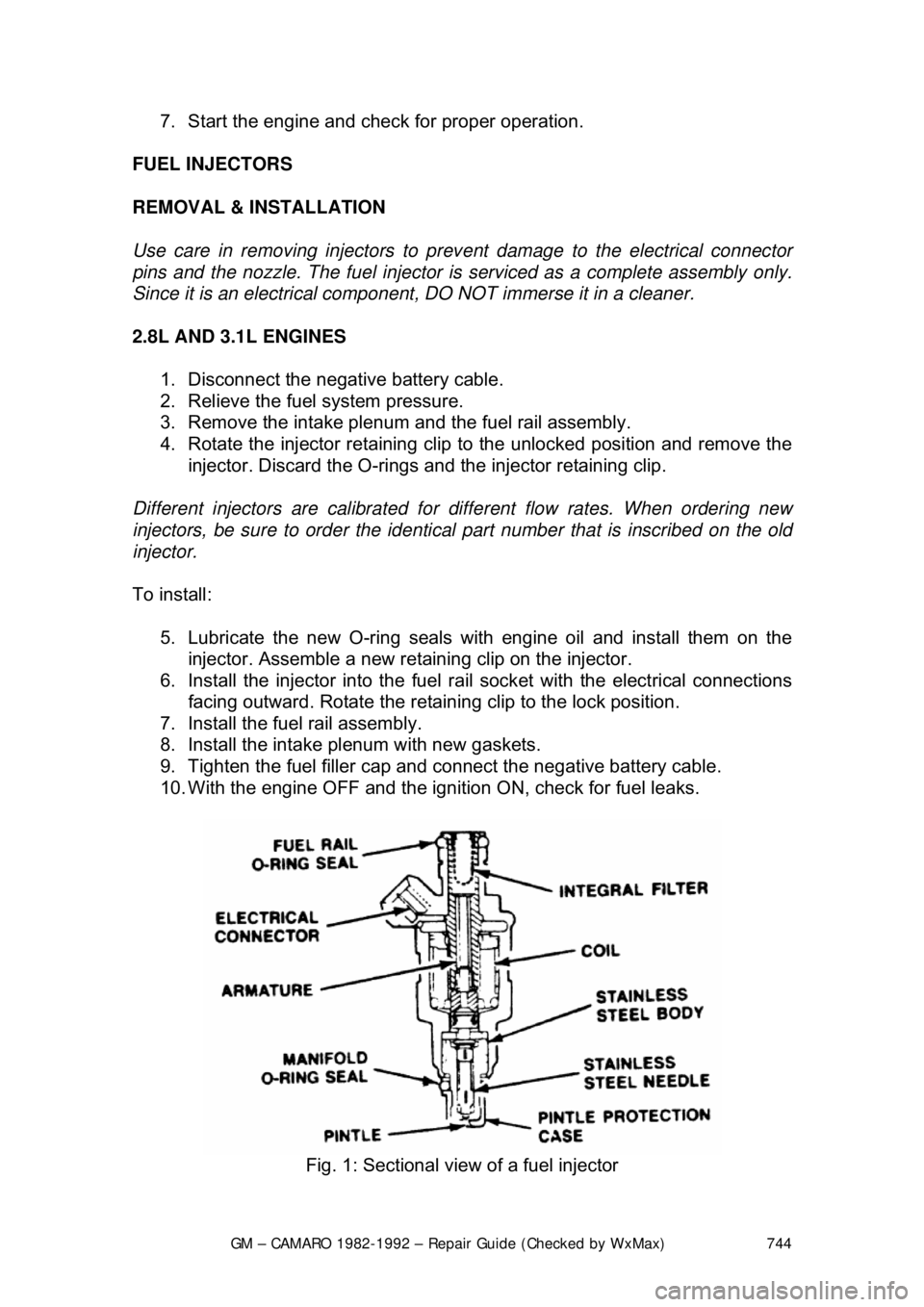
FUEL INJECTORS
REMOVAL & INSTALLATION
Use care in removing injectors to prev ent damage to the electrical connector
pins and the nozzle. The fuel injector is serviced as a complete assembly only.
Since it is an electrical compon ent, DO NOT immerse it in a cleaner.
2.8L AND 3.1L ENGINES 1. Disconnect the negative battery cable.
2. Relieve the fuel system pressure.
3. Remove the intake plenum and the fuel rail assembly.
4. Rotate the injector retaining clip to the unlocked position and remove the
injector. Discard the O-rings and the injector retaining clip.
Different injectors are calibrated for different flow rates. When ordering new
injectors, be sure to order the identical part number that is inscribed on the old
injector.
To install: 5. Lubricate the new O-ri ng seals with engine oil and install them on the
injector. Assemble a new reta ining clip on the injector.
6. Install the injector into the fuel ra il socket with the electrical connections
facing outward. Rotate the retaini ng clip to the lock position.
7. Install the fuel rail assembly.
8. Install the intake pl enum with new gaskets.
9. Tighten the fuel filler cap and connect the negative battery cable.
10. With the engine OFF and the igniti on ON, check for fuel leaks.
Fig. 1: Sectional view of a fuel injector
Page 746 of 875

GM – CAMARO 1982-1992 – Repair Guide (Checked by WxMax) 746
5.0L AND 5.7L TPI ENGINES
1. Disconnect the negative battery cable.
2. Relieve the fuel system pressure.
3. Remove the intake plenum and runners.
4. Remove the fuel rail assembly.
5. Rotate the injector retaining clip to the unlocked position and remove the
injector. Discard the O-rings and the injector retaining clip.
There are two different injector part numbers for the 5.0L and the 5.7L engine.
Do not intermix injectors with different part numbers, as this will result in engine
roughness and excessive emissions. When or dering new injectors, be sure to
order the identical part number that is inscribed on the old injector. However, if a
complete set of injectors is being repl aced, either part number for that engine
application may be used.
To install:
6. Lubricate the new O-ri ng seals with engine oil and install them on the
injector. Assemble a new reta ining clip on the injector.
7. Install the injector into the fuel ra il socket with the electrical connections
facing outward. Rotate the retaini ng clip to the lock position.
8. Install the fuel rail assembly.
9. Install the intake plenum and runners with new gaskets.
10. Tighten the fuel filler cap and connect the negative battery cable.
11. With the engine OFF and the igniti on ON, check for fuel leaks.
FUEL RAIL ASSEMBLY
REMOVAL & INSTALLATION
When servicing the fuel system, be sure to relieve the pressure of the system
and drain the fuel into an approved contai ner. Cap all open fuel lines and plug
any other open passages. DO NO T allow dirt or other contaminants to enter the
system.
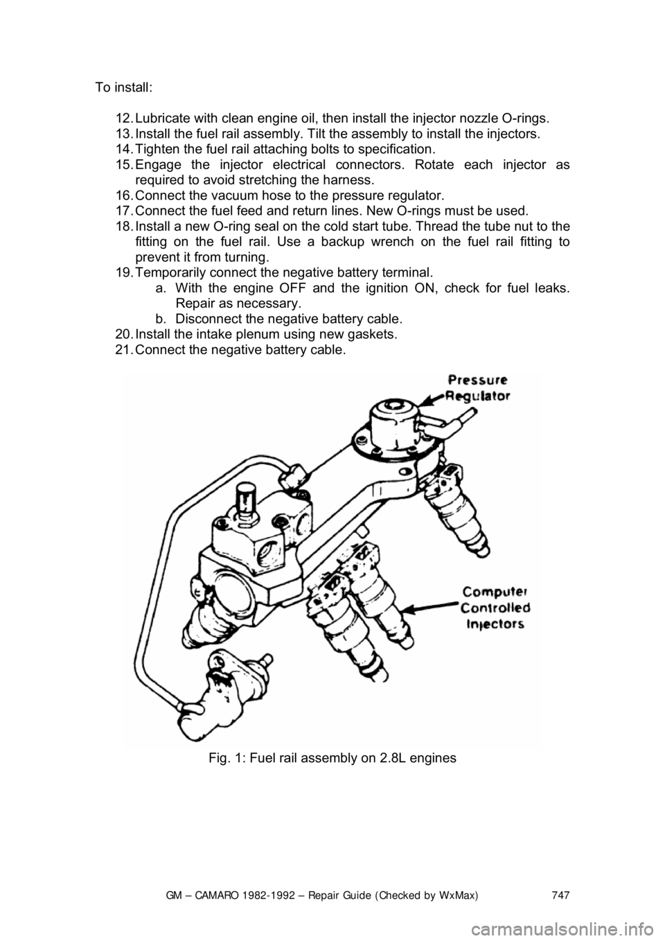
2.8L AND 3.1L ENGINES 1. Disconnect the negative battery cable.
2. Relieve the fuel system pressure.
3. Remove the intake plenum.
4. Clean the fuel rail assembly to pr event dirt from entering the system.
5. Remove the cold start tube at th e fuel rail fitting. Use a backup wrench
on the fuel rail fitting to pr event it from turning.
6. Disconnect the fuel feed and return lines at the rail.
7. Disconnect the vacuum hose at the pressure regulator.
8. Unplug the electrical connectors.
9. Loosen and remove the fuel rail attaching bolts.
10. Remove the fuel rail assembly from the intake manifold.
11. Discard all of the O-ring seals t hat are exposed during this procedure.
Page 747 of 875

GM – CAMARO 1982-1992 – Repair Guide (Checked by WxMax) 747
To install:
12. Lubricate with clean engine oil, then install the injector nozzle O-rings.
13. Install the fuel rail assembly. Tilt t he assembly to install the injectors.
14. Tighten the fuel rail attachi ng bolts to specification.
15. Engage the injector electrical connectors. Rotate each injector as
required to avoid stretching the harness.
16. Connect the vacuum hose to the pressure regulator.
17. Connect the fuel feed and return lines. New O-rings must be used.
18. Install a new O-ring seal on the cold start tube. Thread the tube nut to the
fitting on the fuel rail. Use a backup wrench on the fuel rail fitting t\
o
prevent it from turning.
19. Temporarily connect the negative battery terminal. a. With the engine OF F and the ignition ON, check for fuel leaks.
Repair as necessary.
b. Disconnect the negative battery cable.
20. Install the intake plenum using new gaskets.
21. Connect the negative battery cable.
Fig. 1: Fuel rail assembly on 2.8L engines
Page 750 of 875

GM – CAMARO 1982-1992 – Repair Guide (Checked by WxMax) 750
6. Disconnect the vacuum hose
at the pressure regulator.
7. Unplug the electrical connectors.
8. Loosen and remove the fuel rail attaching bolts.
9. Remove the fuel rail assembly from the intake manifold.
10. Discard all of the O-ring seals t hat are exposed during this procedure.
To install: 11. Lubricate with clean engine oil, then install the injector nozzle O-rings.
12. Install the fuel rail assembly in the intake manifold.
13. Tighten the fuel rail attachi ng bolts to specification.
14. Engage the injector electrical connectors. Rotate each injector as
required to avoid stretching the harness.
15. Connect the vacuum hose to the pressure regulator.
16. Connect the fuel feed and return lines. New O-rings must be used.
17. Temporarily connect the negative battery terminal. a. With the engine OF F and the ignition ON, check for fuel leaks.
Repair as necessary.
b. Disconnect the negative battery cable.
18. Install the intake plenum and runners. Use new gaskets.
19. Connect the negative battery cable.
FUEL PRESSURE REGULATOR
REMOVAL & INSTALLATION
2.8L AND 3.1L ENGINES
The pressure regulator and the fuel rail are serviced as a complete assembly
only. DO NOT attempt to remove the regulator cove r from the fuel rail.
5.0L AND 5.7L TPI ENGINES 1. Disconnect the negative battery cable.
2. Relieve the fuel system pressure.
3. Remove the intake plenum and runners.
4. Remove the fuel rail assembly.
5. Remove the rear crossover re tainer and base attaching screw.
6. Remove the rear crossover tube and O-ring from the regulator base.
Discard the O-ring.
7. Remove the pressure regulator bracket.
8. Remove the pressure r egulator base-to-rail screw.
9. Separate the regulator base from the fuel rail, then disconnect from the
fuel outlet tube.
10. Remove the fuel outle t tube O-ring and discard.
11. Remove the regulator bas e-to-fuel rail connector.
To install: 12. Lubricate and install new regul ator base-to-fuel rail O-rings.