1980 CHEVROLET CITATION ignition
[x] Cancel search: ignitionPage 34 of 95
Downloaded from www.Manualslib.com manuals search engine Oil/Choke Indicator Light
This light will c0!TIe on to provide a "bulb check", w hen the igni tion is turned on, but sh Qu19 go out after the _ engine is started. If tight fails to
come on wit h ignitio~ turned on, it could indicate a burned out bulb , a
defective electric choke hea ter circuit (on L4 and V6 engines), or a blown
instrument lamp fuse. Have system repaired if light does not come on d min g ch eck .
Occa sionally. this light may flicker momentarily while the engine is running. Should this occur, CHECK EN GINE OIL LEVEL as outlined in Section 5,
"Checking Oil Level." If the light comes on continuously, pull over toa safe place and STOP THE ENGINE until the source of trouble can be loca ted and corrected.
The source of tro uble could be any of the following:
• Loss of engine oil press ure (cbec k eng ine oil level).
• Blown choke heater fuse.
• Loss. of electric choke heate r voltage.
Continuing to run the engine with an illuminated oil pressure light can cause
serious engine damage or unusu ally high exhaust system temperature which can
r esult in serio us damage to the
vehicle. Pull over to a safe place and STOP THE
VEHICLE IMMEDIATELY AND SHUT OFF ENGINE. If the light flashe s
momentarily , ch
eck engine oil leve l as outlined in Sectio n 5 of thi s manu al
Choke Warning Indicator Light
On some vehicles equipped with the optiona l oil pressure gage, an amber choke
warning indicator light replaces the red oil pressure indicator light in the
instrument cluste
r. If this light comes on, indicating loss of electric choke heater
volta
ge, have your authoriz ed Dea ler .locate and correct th e tro uble as soon as
p ossib l
e.
Generator Indicator Light The red ligh t GEN will go on when the ignition key is in the "run" _posit ion, but
before the engi ne
is started. After the engine s tarts, the light should 'go out and
r e m ain out .
If th e light remains on when en gine is running , have your Authorized
D eale r loca te and correct the troubl e as soo n as possibl
e.
Engine Temperature .Indicator Light This indicator light is provided in th e instrument cluster to quickly warn of an
overh eated en gi ne. With the igniti on switch in the START position, the red
TEMP indicator (hot light) will light to let you know that it is operati ng prope rly.
When the engi ne is started ;-th e re d light will go out imm ediate ly. It wilUight up
a t n o other time unleSS for some reason the engine reaches a dangerously high ope ra tin g temperature . 1f the light comes on during extreme driving condition s,
such as an exte nded idle, see "E ngine Cooling
System" on page 3-3. Glance at
th e instrument cluster frequently as you drive to see if this
ligh t is on.
Brake System Warning Light
The regular braking system is a dual system designed so that one part will provide
some braking action if there is a loss of hydraulic pressure in the other part of
the system. The system has a "Brake" warning light loca ted in the instrum ent
pane\.
• To serve as a reminder , the "Bra ke" lig ht is designed to come on while the
park ing brake is se t and the ignition key
is on.
• The light is also designed to come on briefly during engine starting so you
can chec k that the bulb is okay.
• Have the system repaired if the light does not come on during engine starting
o r when the parking brake
is set. 2-17
Page 36 of 95
Downloaded from www.Manualslib.com manuals search engine Engine Temperature Gage
This gage indicat~cCX?lant temperature which will vary with air temperature and
operating condition~, The ignition must be on for accurate readings. Hard driving
or prolonged idling In very hot weather will cause the pointer to move beyond the center of the band; Should pointer move to the Red Zone, see "Engine Cooling
System" on page 3-3.
Oil Pressure Gage
The oil pressure gage indicates the pn;ssure at which oil is being delivered 10 the various parts of the engine requiring lubrication. Pressures registered by the gage
I11.!lY vary according to outside air temperatures or weight of oil being used. Oil
pressure of a cold engine ~ing operated at a given speed will be somewhat higher
than when the engine is at normal operating temperature at the same speed .
. Prolonged high speed operation on a hot day at the given speed will result in somewhat lower oil pressure readings. Readings of 30 to 40 psi (205 to 275 kPa)
mny
be considered normal during moderate road speeds of 35 to 40 mph (55 to
60 km/h) \\lith the engine at proper operating temperature. Gage readings which
are
consistently high or Im\l under these conditions may indicate lubrication system
When the engine is operating, the voltmeter indicates the electrical system voltage.
During minimum electrical load, the pointer will read to the right of the center.
As the electrical load is increased,
or in stop-and-go driving, the pointer will rotate
to the left. A meter reading continuously in
the left or right red zone indicates
an electrical system
failure .. Cause of the failure should be determined and corrected~
Light Switch
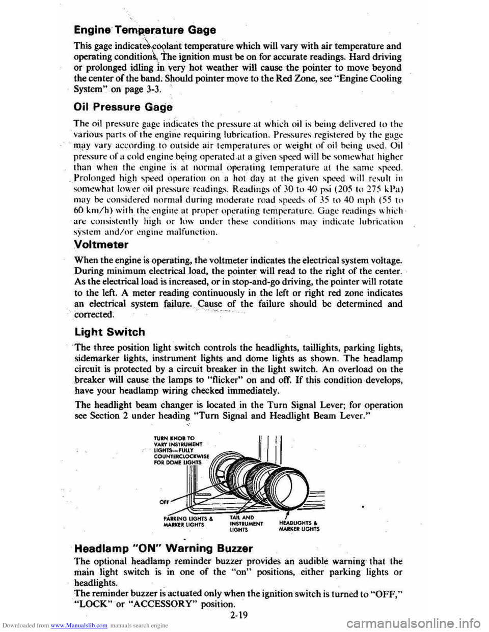
The three position light switch controls the headlights, taillights, parking lights,
sidemarker lights, instrument lights and dome lights as shown. The headlamp
circuit is protected by a circuit breaker in
the light switch. An overload on the
breaker will cause the lamps to "flicker" on and off. If this condition develops,
have your headlamp wiring checked immediately.
The headlight beam changer is located. in the
Turn Signal Lever; for operation
see Section 2 under heading "Tum Signal and Headlight Beam Lever."
TUIN KNOt TO VAr:t'INSTRUMENT lIGHTS_'UtLy COUNTERClOCKWISE RlR DOME
0"
MAltlCfIt LIGHTS , INSTRUMENT LIGHTS
Headlamp "ON" Warning Buzzer
The optional headlamp reminder buzzer provides an audible warning that the
main light switch is in one
of the "on" positions, either parking lights or
headlights.
The reminder buzzer
is actuated only when the ignition switch is turned to "OFF," "LOCK" or "ACCESSORY" position.
2-19
Page 38 of 95
Downloaded from www.Manualslib.com manuals search engine lower Air Vents
Two control handles lOCated beneath the steering column open and close the tower
air vents. To compliment this system there is a power upper vent in the instrument
panel which is operated from the heater
control. The amount of air coming from the lower cutlets ~epends -on vehicle speed and the upper outJet~ depend on fan
'poed.
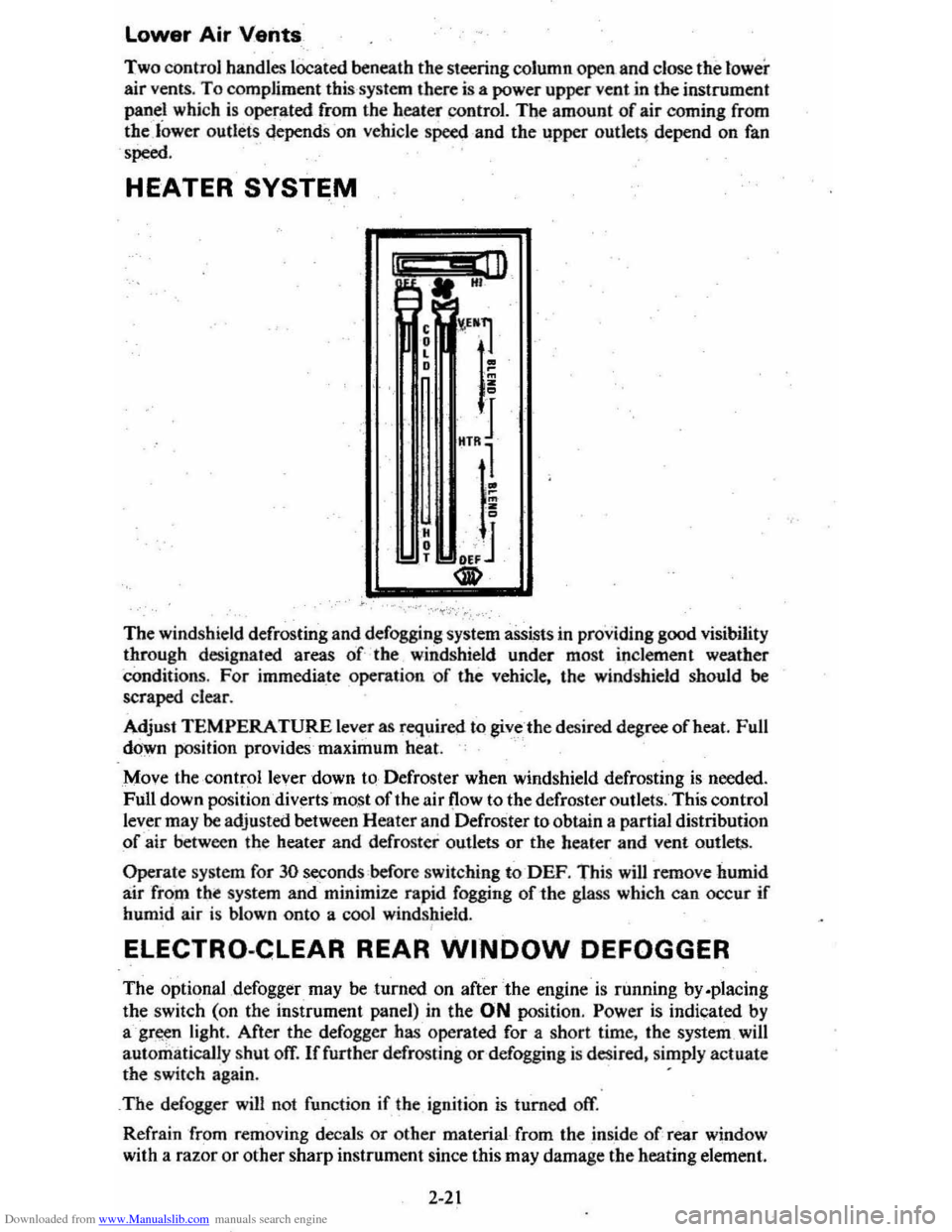
HEATER SYSTEM
I" .. ill A. HI
The windshield defrosting and defogging system assists in providing good visibility through designated areas of the windshield under most inclement weather
Conditions. For immedia_te operation of the vehicle. the windshield should be scraped clear.
Adjust
TEMPERATURE lever as required to giv_c -the desired degree afheat. Full
down position provides'maximum heat.
Move the ·
controllever down to-Defroster when windshield defrosting is needed.
Full down position diverts most of the air (low to the defroster outlets. This control
lever may
be adjusted between Heater and Defroster to obtain a partial distribution
of air between the heater and defroster outlets or the heater and vent outlets.
Operate system for 30 seconds before switching to-DEF. This will remove humid
air from tht system and minimize rapid fogging of-the glass which can occur if humid air is blown onto a cool windshield.
ELECTRO-CLEAR REAR WINDOW DEFOGGER
The optional ,defogger may be turned on after the engine is running by.placing
the switch (on the instrument panel) in the ON position. Power is indicated by
agr~n light. After the defogger has operated for a short time. the system _will
automatically
shut ofT. If further defrosting or defogging is desired. simply actuate the switch again. .
_
The defogger will not function if the ignition is turned off.
Refrain from removing decals
or other material from the inside of rear window
with a
razor or other sharp instrument since this may damage the heating element.
2-21
Page 40 of 95
Downloaded from www.Manualslib.com manuals search engine • NORM (AIR COND) --Outside aids conditioned as it passes through the
system and is discharged from the upper outlets. This position is used for most
air conditioning situations.
• BI-LEVEL (AIR COND) --Outside air is conditioned and directed out the
upper outlets PLUS the heater outlet. A small amount of air also flows from
the defroster outlets. This position provides comfort
and keeps the windshield
clear under low fogging conditions.
• VENT (ECONOMY)-- Outside air is discharged from the upper outlets. This
position is used in cool to moderate weather when refrigeration is not
required. The refrigeration compressor
is turned off.
• HEATER (ECONOMY) --Outside air is delivered from the heater outlet
with a small amount from the defroster outlets. This position is used for most
winter driving. The compressor
is turned off.
• DEF --Outside air is conditioned and delivered from the defroster outlets
with a small amount from the heater outlet. This position is recommended
for conditions of severe fogging and icing only.
Operating Tip
For satisfactory operation of the air conditioning system, windows should always
be closed, except for the
first few minutes to remove hot air if the car has been
sitting.
Air Outlets
Thetwin barrel vertical type center outlets may be rotated or vanes turned to direct
airflow in direction desired. The outlets at each end of the instrument panel may
be rotated or vanes adjusted as desired.
RADIOS
Your vehicle may have one of several optional GM Delco Sound Systems.
GENERAL INFORMATION
Basic Controls-Although a wide variety of features is offered, the following
basic controls are common to all systems.
• Upper Knob -This knob tutns the set on or otT, and controls the volume.
(To use the radio; the ignition mustbe in "Run" or "Accessory;" ) Behind
the volume knob-is a tone control. When turned to the right, it increases treble
and voice clarity; when turned to the left, it increases bass.
• Lower Knob -This knob is a manual tuning control for choosing radio
stations. For radios with rear speakers, a fader control is behind it. This
control adjusts the sound between the front and rear speakers.
• Push Buttons -Each radio has five push buttons you can use to select your
favorite stations. After using a push button, you may have to "fine-tune" the
radio by hand for the best reception.
To
"set up" the push buttons:
L Manually tune to the desired station.
2. Choose the button you wish to use. Pull it straight out, then push it back
in firmly until it stops.
3. Do this for each of the buttons.
On Delco AM-FM radios, the "AM" button simultaneously chooses the AM band
and · an
AM station. The FM button simultaneously chooses the FM band and
an FM station. The remaining three buttons may be used to select either an AM
or an FM station.
2-23
Page 42 of 95
Downloaded from www.Manualslib.com manuals search engine AM-FM Stereo with Citizens Band Transceiver
If your vehicle has an optional Delco GM Citizens Band radio, please refer to
the separdte booklet supplied with this unit.
MOBILE RADIO SYSTEMS
Mobile two-way units are subject to Federal Communications Commission (FCC) regulations' arid must be-installed by trained radio people . Mobile telephones
installed
by your local phone 'company, Citizens Band (CB) radios, and garage
door openers normally will not affect vehicle operation.
If any other mobile radio
transmitters are installed, there can
possibly , be _ adverse effects on vehicle
operation.
Antenna
The standard radioanterma is incorporated in the windshield glass. If necessary,
adjustments for maximum antenna effectiveness can be made by your Authorized
Dealer.
Power. Antenna
The optional power antenna is controlled by the radio. When the radio is ON the
antenna will go up. When the radio is turned OFF either by the ON/OFF knob
or by turning the ignition switch to the OFF poSition, the antenna will go down.
OTHER CONTRQLS AND
FEATURES
Hatchback Coupe
·R.ear Compartment lid -UnlOCk.' and open the lid with your oval hta,d key.
Close the lid firmly to lock.
folding Rear Seilt
The folding rear seat quickly folds to heir provide aq.ditional ,cargo space.
To operate , the folding rear seat:
• Pull the seat cushion forward and up toward the front seatback.
• Pull the seatback strap downward and forward to release the:: seatback latch.
• Swing seatback forward and down to form deck.
• When return.ing seat to the passenger position make sure seatback is latched.
Check now and then to see
if the latch on any folding rear seat works properly.
'To do this. push forward andreat',wai'd on the top of the seatback. If the seat does
not latch properly in the upright. posttion, have it repaired.
Keep
seat belt webbing and hardware clear of seat parts when you tilt folding seats
forward or rearward , This .. helps prevent damage to these bell systems.
CAUTION: The hatchback should be closed while driving to help avoid drawing dangerous exhausigaS8s into the car. (See "Engine Exhaust Gas Caution (Carbon Monoxide)" at the beginning of thi. section.)
2-25
Page 49 of 95
Downloaded from www.Manualslib.com manuals search engine • To lessen the chance of an explosion, never expose a battery to open flames
or electric sparks. Also do not smoke near a ,battery. Batteries give off a gas which is flammable and explosive.
• To lessen the risk of injury incase an explosion does occur, wear eye protection or shield your eyes when working near any battery. Do not lean over a battery.
• Do not allow battery fluid to contact eyes, skin, fabrics, or painted surfaces
because battery fluid is a corrOsiVe acid. Flush any contacted area with water immediately a,nd thoroughly. Also get medical help if eyes are affected.
• To lessen the riskofa short circuit. remove rings, metal watch bands and otl:ler metal jewelry. Also do not allow metal tools to contact at the same time the positive battery terminal (or any metal connected to this terminal) and any other metal em either "ehicle. Make certain when attaching the jumper cable clamps rothe positive terminals of the batteries that neither clamp contacts any other metal.
• This
vehicle has a 12 volt battery and a negative ground electrical system. Make sure that the other vehicle als~ has a 12 volt battery and that the negative terminal, is .'grounc::ted(attached to a metal, part of the vehicle). Its owner's manual may give you that information, If unsure of the other vehicle's voltage (or if the voltage and/or ground on the other vehicle are different from your vehicle). do not try to jump startas personal injury or severe damage to electrical and electronic parts may result.
• If the discharged battery has filler caps. check the fluid level. ( 00 not check with an Op~tn flame and db not smoke .) Add clear drinking water to the proper level if low, and replace the caps before jump starting.
I. Position, the vehicle with'the good (charged)ba,.ttery so that the jump starting
cables will reach.
Do not let the vehicles t"ouch.
2. Turn off all electric motors and accessories in both vehicles. Turn off all lights
except those needed to protect the vehicles or light up the work area. Turn
off the ignition, apply the parking brake firmly, and shift the automatic transaxleto "p"o.?ark) (manual transaxle to "N"(Neutral) in both vE-hicles.
3. Jumper Cable Connection Instructions (See illustration) .
• Connect the first jumper cable from the positive" +" (red) terininal on
one battery to the positive "+" (red) terminal on the other battery.
Never, connect "+" (red) to "~" (black), or '\" to "+".
• Next, connect one end of the second cable to the grounded negative "."
(black) tenninal of the good (charged) battery.
• Lastly, connect the othetend of the second jumper cable to a solid,
stationary, metallic point on the engine of the vehicle with the discharged
battery but at a
point away from the battery --450 millimeters (18 '1
inches) or more from the battery if possible. Do not connect it to or attach it near pulleys, fans, or other parts that will move wHen the engine
is started. Don't touctt hot manifolds as they _can cause severe burns. If hot or moving parts can be avoided, the MOUNTING BRACKETS for
the Delcotron generator,
or the air conditioner compressor, ,generally
make a good point for-this final ground attachment. Take care that the
jtimper cable does
hot contact moving parts on or near the generator
or compressor.)
4. Start the engine of the vehicle with the good (charged) battery and run the
engine at a moderate speed.
3-2
Page 63 of 95
Downloaded from www.Manualslib.com manuals search engine CATALYTIC CONVERTER
. The catalytic converter is an emission control device added to the
exhaust system to reduce exhaust gas pollutants. The converter
contains a ceramic material coated with noble metal catalysts. To prevent
contamination of the cata lysts,
unle~ded gasoline must be used. Unleaded gasoline
also reduc es combustion chamber deposits and exhaust system corrosion.
The catalytic converter requires the use of unleaded gasoline. Use
of leaded gasoline will cause the converter to lose its effectiveness for emission control. On some engines, the catalyst must be changed at cer tain inter vals in orde r for
the emissio n control system to continue to operat e properly. The change intervals
are speci fied in Section C of the Maintenance Schedule folder.
On cars that require this catalyst change, the word "EMISSION" will
appear on an indicator in the speedometer face at the specified change
in terval
s. This is a reminder that the cata lyst must be changed. (If the indicator does not appear, your car does not need this catalyst change).
Your Chevrolet deale r will perform the lirst cataly st cha nge at no charge, whether yO'u are the first owner or a subsequent owner. As part of this service, the indicator
should be reset to appear
at the next specified chang e interval. To help prevent
damage:
1. Keep your engine properly maintained. Engine malfunctions involving th e electrical, carburetion or ignition systems may result in unusually high
conve rter and exhaust system temperatures .
Do not keep driving your vehicle if you detect engine misfire. noticeable loss of
perform,8nce. or other unusual operating conditions. Instead, have it serviced promptly. A properly ···maintained engine will he lp avoid
malfunction s that could damage the converter.
It will also help provide good
emissio.n cq!).,trol and gasoline economy. See the Maintenance Schedule folder
for inform ation on inspecting a
nd maintaining the engi ne. exhaust system.
and other compone nts.
2 .
Do not drive through, idle, or park your vehicle over combustibl e materials,
s u ch as grass
or leaves. They could 'touch the hot exhaust system and ignite.
3. Do n o t push or tow this vehicle 10 stan it. This cou ld damage (he converter.
Disregarding this information could damage the catalytic converter, the vehicle,
or nearby property.
C-4 (COMPUTER CONTROLLED CATALYTIC CONVERTER)
SYSTEM If your new car was purchased in California, it has a special emission control
system, called
the C-4 (Computer Co ntrolled Catalytic Converter) System. The C4 System monitors the exhaust stream with an oxygen sensor. Based 4
on senso r signals, the electr onic control module adjusts the carburetor
air~fuel ratio as needed. It is very important to use only unleaded gasoline
in cars with
the C-4 System. Leaded gasoline will damage the oxygen
sensor. which may affect emission
control, fuel economy and drivability.
Some cars equipped with the C-4 System need an oxygen sensOr change
at the intervals specified in Section C of the Maintenance Schedule folder.
On these cars, an oxyge n sensor maintenance reminder is included in the
instrument paneL The word "EMISSIONS" is designed to appear in a
window in the speedometer face at the intervals outlined in the Maintenance
Schedule folder. The "EMISSIONS " indicator is a reminder that the oxygen
sensor must be repl aced with a new sensor.
Such replacement is necessary
in order to maintain the correct operation of the emiss ion control system.
The indicator must be reset as part of this service.
5-2
Page 66 of 95
Downloaded from www.Manualslib.com manuals search engine NOTICE: You cannot read the correct fluid level if you have just driven the car for a long time at high speed, in city traffic in hot weather, or if the car has been pulling a trailer. Wait. until the fluid has cooled down (about 30 minutes).
Remove the dipstick located on the driver's side forward of the cowl. Carefully
touch the wet end of the dipstick to find out if the fluid is cool, warm or hot. Wipe
it clean and push it back in until the cap seats. Pull
out the dipstick and read the
fluid level.
• If it felt cool or warm (about room temperature), the level should be
between the dimples above the "Full" mark.
• If it was too hot to hold. the level should be at or in the hatched area.
Add just enough DEXRON-®n fluid to fill the transaxle. It takes only 0.5 liter
(one pint)to raise the level from "Add" to "Full" with a hot transaxle.
Do not overfill the transaxle. Overfilling can cause foaming and loss of fluid, which
could result in transaxle damage.
Automatic Transaxle Drain Intervals
Change the transmission fluid and change the filter (or clean the screen) as
outlined in Section
A of the Maintenance Schedule folder.
ELECTRIC FAN
CAUTION: Keep hands, tools, and clothing away from the angine cooling fan to help prevent personal injury. This fan is electric and can come on whether or not the engine is running. The fan can start automatically in response to a heat sensor when the ignition is in the "Run" position.
ENGINE COOLING SYSTEM
The coolant recovery system is standard. The coolant in the radiator expands with
heat, and the overflow collects in the recovery tank. When the system cools down,
the coolant
is drawn back into the radiator.
The cooling system was filled at the factory with a quality coolant that meets
GM Specification 1899-M. The cooling system is designed to use coolant (a mixture
of water and ethylene glycol antifreeze) rather than plain water. The coolant
solution should be used year round. It has many advantages, such as:
• provides freezing protection down to _37°C, (-34°P)
•
provides boiling protection up to 128QC, (262°P)
•
protects against rust and corrosion in the cooling system,
• maintains the proper engine temperature for efficient operation and emission
control, and
• allows proper operation of the coolant temperature light (or gage).
See Section A of the Maintenance Schedule folder to find out when the coolant
must
be replaced.
COOLING SYSTEM CARE
Check the cooling system at regular intervals, such as during fuel stops. You
usually do not need to remove the radiator cap to check the coolant level. Lift
the engine hood and look at the "see through" coolant recovery tank. When the
engine
is cold, the coolant level -should be at or slightly above the "Full Cold"
mark on the tank. When the engine has fully warmed up, the level should be at ')r slightly below the "Full Hot" mark on the tank. If the coolant level is low,
5-5