1980 CHEVROLET CITATION radio controls
[x] Cancel search: radio controlsPage 33 of 95

Downloaded from www.Manualslib.com manuals search engine '" 0;
o STANDARD
o OPTIONAL
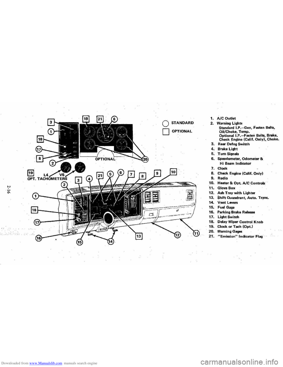
1. AIC Outlet 2. Warning Lights
Standard I.P.-Gen, Fasten Belts.
Oil/Choke, Temp.
Optionall.P.-Fasten Belts, Brake,
Check Engine (Calif. Only), Choke. 3. Rear Defog Switch
4. Brake Light
5. Turn Signals
6. Speedometer, Odometer & Hi Beam Indicator
7. Clock
8. Chack Engine (Calif. Only)
9. Radio 10. Heater & Opt. Ale Controls
11. Glove Box
12. Ash Tray with Lighter 13. Shift Quandrant, Auto. Tr~ns_.
14. Vent Levers 15. Fuel Gage
16. Parking Brake Release
17. Light Switch
18. Delay Wiper Control Knob 19. Clock or Tach (OptJ
20. Warning Gages
21. "Emission" Indicator Flag
Page 40 of 95

Downloaded from www.Manualslib.com manuals search engine • NORM (AIR COND) --Outside aids conditioned as it passes through the
system and is discharged from the upper outlets. This position is used for most
air conditioning situations.
• BI-LEVEL (AIR COND) --Outside air is conditioned and directed out the
upper outlets PLUS the heater outlet. A small amount of air also flows from
the defroster outlets. This position provides comfort
and keeps the windshield
clear under low fogging conditions.
• VENT (ECONOMY)-- Outside air is discharged from the upper outlets. This
position is used in cool to moderate weather when refrigeration is not
required. The refrigeration compressor
is turned off.
• HEATER (ECONOMY) --Outside air is delivered from the heater outlet
with a small amount from the defroster outlets. This position is used for most
winter driving. The compressor
is turned off.
• DEF --Outside air is conditioned and delivered from the defroster outlets
with a small amount from the heater outlet. This position is recommended
for conditions of severe fogging and icing only.
Operating Tip
For satisfactory operation of the air conditioning system, windows should always
be closed, except for the
first few minutes to remove hot air if the car has been
sitting.
Air Outlets
Thetwin barrel vertical type center outlets may be rotated or vanes turned to direct
airflow in direction desired. The outlets at each end of the instrument panel may
be rotated or vanes adjusted as desired.
RADIOS
Your vehicle may have one of several optional GM Delco Sound Systems.
GENERAL INFORMATION
Basic Controls-Although a wide variety of features is offered, the following
basic controls are common to all systems.
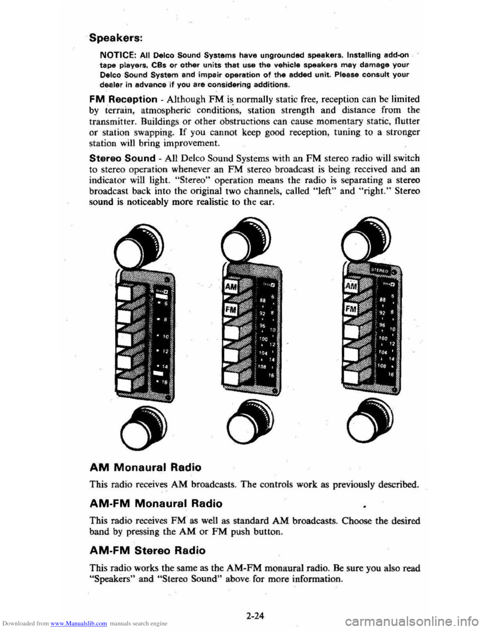
• Upper Knob -This knob tutns the set on or otT, and controls the volume.
(To use the radio; the ignition mustbe in "Run" or "Accessory;" ) Behind
the volume knob-is a tone control. When turned to the right, it increases treble
and voice clarity; when turned to the left, it increases bass.
• Lower Knob -This knob is a manual tuning control for choosing radio
stations. For radios with rear speakers, a fader control is behind it. This
control adjusts the sound between the front and rear speakers.
• Push Buttons -Each radio has five push buttons you can use to select your
favorite stations. After using a push button, you may have to "fine-tune" the
radio by hand for the best reception.
To
"set up" the push buttons:
L Manually tune to the desired station.
2. Choose the button you wish to use. Pull it straight out, then push it back
in firmly until it stops.
3. Do this for each of the buttons.
On Delco AM-FM radios, the "AM" button simultaneously chooses the AM band
and · an
AM station. The FM button simultaneously chooses the FM band and
an FM station. The remaining three buttons may be used to select either an AM
or an FM station.
2-23
Page 41 of 95

Downloaded from www.Manualslib.com manuals search engine Speakers:
NOTICE: All Oelco Sound Systems have ungrounded Sp8li!kers. Installing add-on tape players. CBs or other units that use the vehicle speakers may damage your Delco Sound System and impair operation of the added unit. Please consult your dealer in advance -i f you are conSidering additions.
FM Reception - Although FM is normally static free, reception can be limited by terrain, atmospheric conditions, station strength and distance from the
transmitter. Buildings or other obstructions can cause momentary static, nutter or station swapping. If you cannot keep good reception, tuning to a stronger
station
will bring improvement.
Stereo Sound - All Delco Sound Systems with an FM stereo radio will switch
to stereo operation whenever -an FM stereo broa dcast is being received and an
indicator will light. "Stereo" operation means the radio is separating a stereo
broadcast back into the original two channels, called "left" and "right." Stereo
sound is noticeably more realistic to the ear.
AM Monaural Radio
This radio receives AM broadcasts . The controls work as previously described.
AM-FM Monaural Radio
This radio receives FM as wen as standard AM broadcasts . Choose the desired
band
by pressing the AM or FM push button .
AM-FM Stereo Radio
This radio works the same as the AM-FM monaural radio. Be sure-you also read "Speakers" and "Stereo Sound" above_ for more information .
2-24
Page 89 of 95

Downloaded from www.Manualslib.com manuals search engine Catalytic Converter ..................................... . 5·2 C.4S~m . CHECK ENGINE Light.. .... : ..... . 2·18,5-2 2-18,5·2 Eldla~t Gas Csution ._ .... _ ...... . Fuel Requirements IGu, ._ .... ..
SENSOR Indie.tOt' .............. . Engin.
2· 2·2 2.18 •. 5.2
e.lts .... , ........ . (See M.int.n.nce SChedule) Br •• k·ln .... . ................................. 2-2 Cod ........... . Cooling .............................. .................... . Exh.ust Ges C.ution .................... .. Flil. to St.rt ........
,.,
5·5 2· 2·0 Flooct.d ,St.rting........... 2·g Fu.1 Recommend.tion (See "Fu.1'1 I~ntification ...... _........................................ 7-5 Jump St.rting ........................... 3·1 OiL.......... ....................... (5 .. "Oil, Engine'" Overh •• ting.. ....................... . 3.3 Speclflc.tions.. ............................................ 7·1 St.rtlng. Cold Weather ........................... ".. 2·9 St.rtlng (GI,oline). 2-8 T.mp.r.ture G.g..................... ................ 2-19 T.mp.ratur. Light ..................................... 2 ·17 Th.rmostlt. ............ ..................................... 5·7 Enolne Olt.. (S .. "Oil. Enginlt '')
Ethylane Gly<:ot AntifrNZe ......... 5·6 exhauSt Gn C.U1iOfI.._ .... Exhlu.t Sy.tem Inspection .. Exterior Fini.h C.ra .............. ............... .. F.bric Care ............................................ .. F.n, Halter" Air Cond ............................ .. FASTEN SEAT BELTS Light .......... ............. . FI.tener., Repllcemant Filte~ Air CI •• n.r ... .. Fini.h C.r ... . Finilh Olm.g • .. flammable Cle.ners ................................. . FI •• ,,-,.
HI,Zlrd Wlmi"il .. Turn Signll .............................. .......... .. Flood.d Engine, St.rting .. Floor Control ....
Fluid C.p.cili ................................. ............. .. FM Radio'
2· 2· 4·4 ' ·2 2·21 \·8 5·
5 ·8 4·4
4" 4·
3 · 2-0 2·. 2·13 ,. 2·24 Folding Se.ts ........ For.lgn Countries , Operation in .. 1·5 , 2·25 2·3 Four ·W.y Hazard FI.sher ..... .. FrHdom Bett.ry ......... .......... .. FrHing C.r Wh.n Stuck. ..................... . Fue' C.p... .. ............................ ............ .. Economy Tips .. Glge .................................... .. G, •• oUne Oct.ne R.ting ................................. ........ . Ov.~e •• Oper.tion ... Tlnk C.pecity .. Fu •• Ch.ft. ......
3· 5 ·. 3·'
, . 2·' 2 ·15 2·2 2 ·2 2·3 7·
7·4 Circuit Bre ... ers ....... _................. 7-" G.ga. Engin. Temper.ture 2 ·18 Fuel ..... ...... ............ ......... 2·15 Oil Pr •• sur ... T.chometer (Engin. Sp.ed) 2·17 2·19
7·7
Volt!"etftr .............. ................................. ....... 2·19 G.soIina ......... . .......... ....... _._... (Sa. "Fu.I") GEN (G.nerator) Livht 2:17 GI ... CI •• ning ................... _ .... .... _............. '·3
Glove 8011. ............................ _....................... 2 .1 6 Gu.rd Ao-irtSt T".ft ... ~...... 2-2 Hu.rd W.rning FI.sher.. 3·1 H.adlights Circuit are.ker.. 7_. Dimm.r Switch.. 2 ·1' Instrument P.n.1 Switch.. 2 ·15 lights ON Reminder 2 -19 He.ted R .. r Window......... ................ ........ 2·2,. H.ater/Alr CondltiOfler2·20, 2·21
High·e •• m H •• dlivhts........................ 2·7
Hitches , Tr.iI.r ............................. _......... 1.12 Hood L.tcha. Iln.ide B.ck Co~r) Hood R.l"H... (Inside B.ck Cowr) Horn ............................ ......... 2.13 HOT light ........ 2 ·17
Identificltion Numbers ........................... ....... 7·5
Ignition
K.V· .... · .. · ................ . Lock In Case of Emar;ency ... Indicator L~ht •.. Infenl Se'1I " Renr.in\.. Infl.tion Pres.ure. Tires Inl.ts, Air .............................. _ .... .. Inside R •• rviaw Mirror .. Instrum.nt P.n.1 &. Controls ...
\.
2·' 3 · (SH " lightS'') 1·10 5 ·11 2·20 '·3 2·15 Int.rior ApP41.r'nce C.re . ..................... ...... ,., Interior" Instrum.nt lights.. (See "lights'" J.ck Operation&. Stowlge.. 3·5. 3.8 Jump Stlrting .......... 3~" Keys ..... 1-1 Lan. Change 8t Turn Signals 2-6 L.p-Shoulde, Baits.. {See "Seat Belts ",
Latches
Folding S •• t~c"" .. 1·5 .2 ·25 Hood ....................... .. S •• tb.c", Front.. Leather Trim Cer ...
(Ins ide Back Cover) \·5
light.r, Clgar.ne ... lights BRAKE ......... .. Brights On ..... . Bulb Ch.rt.. CHECK ENGINE ... Dimmer SwitCh , Hndlight...
Electricel Svst.m (GEN) ENGINE ( O il & /or CI\o"e) Engin. TemP41f.ture (HOT) .. FASTEN SEAT BELTS .. GEN (EI.ctric.I System) ... Hazard W.rning FI.sher ... H •• dlight Circuit br.aker H •• dlight SwitCh ... H •• dlights On Reminder HEAT (Cat.lytic Convert.r) .. High·Beam Indicator HOT: .......................................... .. Instrum.nt P.n.1 Interior .......... . OIL (Pr.ssur.) .. Parking .... Se.t B.lt Remind.r ...
4 ·3
2 -20
2·17 2· 7 '·3 2 ·18. 5·2 2·' 2 ·17 2 ·11 2 ·17 \·8
2 ·17
3 · , .. 2 ·7,2·19 2-1Q 2·18, '5-2 2·7 . 2·19 2 ·17
2 -1E1 2·19 2·17 2·" ,1 ·8