Page 337 of 625
6E.461973OPELSERVICEMANUAL
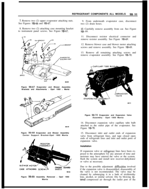
Sectional View Of Carburetor
1Carburetor cover
2Vent valve
3 Ball valve (pressure valve)
4Injection tube
5Primary venturi
6Choke valve
7Vent
iet8 Air correction
iet9Enrichment
10 Float needle valve
11 Float needle valve seal ring12 Fuel line connecting tube
13 Carburetor cover gasket
14Leaf spring
15Float
&amber16 Pressure reduction valve17Pump lever
18Diaphragm
19 D iophragm spring
20 Ball valve (suction valve)
21Float
22 Pump connecting rod
23Metering
iet24Emulsion tube
25 Bore without function
26Throttle valve
27Intermediate lever
28Main venturl
29 Vacuum passage for automatic choke
30 Throttle valve body
31Gasket
32 Vent valve lever
Figure 6E-2 Sectional View of Carburetor
Page 338 of 625

CARBURETOR AND THROTTLE LINKAGE65 47
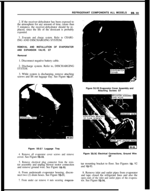
Figure 6E.3 Secondary Vacuum Diaphragm
Figure
6E-4 Automatic Choke System
Figure
6E-5 Idle Systemin a richer mixture. When the throttle valve is
opened, fuel is also drawn from the upper ports,
providing a good transfer from the idle system to the
main metering jet system. See Figure
6E-5.Main Metering Jet System
During high-speed operation, fuel is drawn from the
float chamber through the main metering jet (Figure6E-2) into the emulsion tube bore. The emulsion
tube, which is provided with transverse bores, is in-
serted in the emulsion tube bore. Vacuum in the
primary venturi (Figure 6E-2) draws fuel from the
main nozzle. As the vacuum increases, the tendency
is to draw too much fuel from the main nozzle, mak-
ing the mixture too rich. To compensate for this
tendency, the fuel level drops in the emulsion tube
bore and more emulsion tube transverse bores are
exposed. Air from the high speed air jet (Figure6E-2) enters the emulsion tube through these trans-
verse bores and mixes with the fuel. The more the
fuel level drops, the more the transfer bores are ex-
posed. This causes the air-fuel ratio to remain con-
stant over the whole engine speed range. See Figure
6E-6.Figure
6E-6 High Speed System
The secondary valve diaphragm is operated by
vacuum taken from the mixing chamber of the pri-
mary barrel on the Opel 1900 and Manta only. With
the primary throttle valve almost open and with en-
gine speed at approximately half of the maximum
engine RPM, vacuum increases to such an extent
that the secondary throttle valve starts opening from
vacuum applied in the vacuum diaphragm case act-
ing through a connecting rod and throttle valve
lever. See Figure
6E-3.
Primary to Secondary Transfer SystemIn order to have a smooth engagement of the
second-
Page 339 of 625

6~. 46,1973 OPEL SERVICE MANUAL
ary barrel, it is provided with g transfer system.
When the secondary throttle valve starts to open,
two‘ports (which are normally just above the closed
valve) are uncovered, causing fuel to feed into the
secondary bore just before the secondary nozzle
starts feeding. This provides for an additional enrich-
ment of the air-fuel mixture at the beginning of full
throttle operation. See Figure
6E-7.
nInFlFigure
6E-7 Primary to Secondary Transfer System
Full Thrdttle Enrichment SystemIf the secondary throttle valve is fully opened, the
vacuum in the throttle valve area is reduced so that
the transfer ports (mentioned above) stop feeding.
However, the vacuum increases greatly in the sec-
ondary venturi area. An enrichment tube which pro-
trudes into the primary venturi area, feeds fuel
continuously during full throttle operation. See Fig-
ure
6E-2.
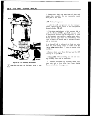
Acceleration SystemWhenever the throttle is closing, the suction stroke
of the diaphragm pump causes fuel to flow from the
float chamber through the inlet ball valve into the
pump chamber. When the throttle valve is opened
the diaphragm is moved inward by the pump con-
necting rod and the pump lever. Fuel is injected into
the primary bore through the injector tube. The
amount of fuel is determined by the pump stroke.
The inlet ball valve in the pump chamber prevents
fuel from flowing back into the float chamber during
the pressure stroke of the pump. The outlet ball valve
prevents air from being drawn into the injector tube
during the suction stroke of the pump. See Figure6E- 8.
Float Bowl VentilationWhile driving, the float bowl is ventilated from insideFigure
6E-8 Acceleration System
the carburetor. That is, the float bowl is connected
through the vent valve with the area under the air
cleaner.
When the engine is idling or off, the ventilation from
inside is cut off and ventilation from the charcoal
canister is cut in. The upper spring now seats the
valve on the upper seat. See Figure
6E-9.
-6E-9
Figure
6E-9 Float Bowl VentilationThe advantage of an inside vent while driving is that
air cleaner restriction does not enrichen the air fuel
mixture. The purpose of the charcoal canister vent
while idling or after shutting-off a hot engine, is to
prevent excess fuel vapors from entering the intakemanifold and outside air. Excess fuel vapors may
cause an idling engine to stall, or may make it dif-
ficult to restart a hot engine.
Page 340 of 625

CARBURETOR AND THROTTLE LINKAGE6E- 49DIAGNOSIS
CARBURETORCondition I
Hesitation or Stall Upon Light AccelerationCorrection
1. Check spark plugs and plug gap. Plug gap should
be
,030 in.
2. Check dwell and timing.
3. Adjust carburetor.
4. Accelerator pump should discharge fuel between
throttle plate and venturi wall with engine off. If aim
is not correct, use needlenose pliers to slightly bend
nozzle so proper aim is achieved. See Figure 6E- 10.
CORRECT ACCELERATOR
PUMP DISCHARGE
NOZZLE AIM
\Figure 6E-10 Pump Shot Aim
Road test car. If hesitation still exists, check for the
folI0 wing:1. Plugged accelerator pump discharge nozzle.2. Dirt in accelerator pump circuit.
3. Defective inlet check ball.
4. Defective accelerator pump pressure relief valve.
5. Defective accelerator pump diaphragm.
6. Maladjusted accelerator pump linkage.
Condition II
Hard Start Afier Hot Soak
CorrectionPerform Steps l-4 in Condition I.
Condition Ill
Hard Start When Engine Is Cold
Correction1. Align groove on choke cover with pointer on
choke housing. See Figure
6E-17.2. Set fast idle.
3. Replace distributor points if pitted.
4. Check spark plugs and gap at
,030.5. Set dwell and timing.
If above procedure does not correct problem, replace
with new automatic choke assembly.
Condition IV
Rough, Erratic, or No Idle
Correction1. Check spark plugs and gap at
,030.2. Check dwell angle and ignition timing.
3. Clean idle jet and passages with air hose. See Fig-
ure
6E-5.4. Check manifold to head bolt torque. Should be 33
lb.ft.5. Check automatic choke linkage alignment.
6. Adjust carburetor.
Page 341 of 625

6E- 501973 OPEL SERVICE MANUALMAINTENANCE AND ADJUSTMENTS
IDLE SPEED ADJUSTMENT
Note:
Idle speeds of 600 to 800 R.P.M. are normal
for engines with less than
3,ooO miles.Prior to making any adjustment to the carburetor,
the following items must be checked for proper oper-
ation and/or setting:
1. Valve Adjustment (Hydraulic lifters can be im-
properly adjusted.)
2. Dwell Angle.
3. Ignition Timing.
4. Spark Plug Gap.
5. Exhaust Gas Recirculation Valve (See “Check-
ing” under EXHAUST GAS RECIRCULATION
SYSTEM.)
After it has been ascertained that the above items are
properly adjusted and operating correctly and idle
R.P.M. is still not within specifications, proceed as
follows:
1. With air cleaner installed, run engine until normal
operating temperature is reached.
2. Remove plastic caps from the idle mixture screw
and air speed screw. See Figure
6E-11.Figure
6E-1 1 Carburetor Adjusting Screws
3. To raise R.P.M., turn air speed screw counter-
clockwise. To lower R.P.M., turn air speed screw
clockwise, thereby reducing the amount of air going
through the system.4.
Ad,just idle mixture screw until highest R.P.M. is
obtained. Alternately adjust idle mixture screw and
air speed screw until R.P.M. is obtained that is 50
R.P.M. higher than the desired final setting. This is
to be accomplished with the idle mixture screw at
best idle.
5. Turn idle mixture screw clockwise (lean) until a
decrease of 50 R.P.M. is obtained. The idle R.P.M.
will
n.ow be within specifications and proper emis-
sion control maintained.
6. Install red plastic caps over the air speed screw
and idle mixture screw.
Basic Idle AdjustmentA basic idle adjustment is to be made only if engine
idle R.P.M. correction does not result in correct idle
R.P.M. setting and engine has more than
3,OOO miles
of operation. If necessary, proceed as follows:
1. Remove plastic cap from the throttle valve stop
screw. See Figure
6E-11.2. Place the Manometer (J-23951) in a vertical posi-
tion. Turn the 2 vents on top open to equalize pres-
sure and balance gauge to read zero. With engine
idling, unplug the vacuum advance hose from the
carburetor and connect the manometer hose in its
place. See Figure 6E- 12.
Figure 6E-12 Throttle Plate Calibrator J-23951
Installed3. If the manometer does not read 1 to 8 inches of
Page 342 of 625

CARBURETOR AND THROTTLE LINKAGE6E- 51
water, adjust the throttle stop screw to read 6 inches
of water (3 inches down and 3 inches up).
4. Disconnect manometer and reconnect the vacuum
advance hose.
5. Adjust idle air speed screw and mixture screw to
obtain maximum idle at 850 to 900 R.P.M. (auto-
matic transmission) or 900 to 950 R.P.M. (manual
transmission).
6. Make final adjustment by turning idle mixture
screw in to reduce idle speed 50 R.P.M.
7. Install red plastic caps over the air speed screw
and idle mixture screw. Replace plastic cap over the
throttle valve stop screw and secure in place with
Loctite.
Fast Idle Speed Adjustment
1. Remove air cleaner cover.
2. With engine off, open the throttle halfway and
close the choke valve, release the throttle, then re-
lease the choke.
3. Start engine without moving the throttle. Adjust
to 3200 to 3300 R.P.M. using 2 nuts on fast idle rod.
See Figures 6E-13 and
6E-14.Figure
6E-13 Decreasing Fast Idle Speed
CARBURETOR LINKAGE ADJUSTMENT
GT Series1. Remove air cleaner.
2. Have helper depress accelerator pedal to floor and
check to see if wide open throttle is reached at carbu-
retor.
3. If adjustment is necessary, proceed as follows:
6E-14Figure
6E-14 Increasing Fast Idle Speed
(a) Unhook accelerator pedal return spring.
(b) Remove lock spring at upper end of vertical con-
trol rod and detach rod.
(c) Lengthen or shorten control rod so that wide
open throttle is obtained at the carburetor when ac-
celerator pedal is
l/4” - l/2” from floor mat.
(d) Reinstall rod, lock spring and pedal return
spring.
Opel 19W and Manta SeriesThe carburetor bowden control wire is properly ad-
justed if, with correctly-adjusted engine idle speed,
engine at operating temperature and accelerator
pedal at an angle of 25 degrees to the vertical plane,
the ball (A) of the carburetor bowden control wire
rests against the accelerator pedal lever. See Figure
6E-15.
1. Position accelerator pedal at an angle of 25 degrees
to the vertical plane. To do this, loosen lock nut of
adjusting bolt (c) and unscrew adjusting bolt a few
turns.
Squeeze a 1 3/S” wood block (D) between accelera-
tor pedal and dash panel. See Figure
6E-15.Screw in adjusting bolt until the accelerator pedal
lever releases the wood block (D). Tighten lock nut.
2. Adjust bowden control wire at adjuster. See Figure
6E-16. Prior to doing this, adjust engine idle speed
with engine at operating temperature.
Set carburetor bowden control wire adjuster at the
bracket so that the ball (A) of the control wire rests
against part (B) of the accelerator pedal lever and the
wire core between bracket and segmental disc is not
sagging.
Page 343 of 625

6E. 521973 OPEL SERVICE MANUAL
Figure 6E-15 Adjusting Accelerator Cable
Depress accelerator pedal until pedal lever touches
floor mat. The carburetor throttle valve must now be
completely opened.MAJOR REPAIR
REMOVE AND INSTALL CARBURETOR1. Remove air cleaner.
2. Remove fuel and vacuum hoses from carburetor
fittings.
3. Remove choke wire.Figure 6E-16
Bowden Control Wire Adjuster and
Segmental Disc
4. Disconnect throttle linkage by removing lock pin
and unsnapping ball socket from ball on end of throt-
tle shaft.
5. Remove carburetor by removing four nuts and
lockwashers.
Install in reverse order, noting the following:
1. Prior to carburetor insta!lation, place a new gasket
on intake manifold.
2. Make certain that all nuts and screws on the car-
buretor are securely tightened.
3. Make sure that choke housing is set on index and
that choke valve is nearly closed at room tempera-
ture. See Figure
6E-17. Make sure choke valve is free
in all positions.
Figure
LiE-17 Choke Housing Set on Index
Page 344 of 625

CARBURETOR AND THROTTLE LINKAGE6E- 63
4. Adjust engine idle speed and mixture
CAUTION: : Make sure choke valve opensfully before starting idle adjustment.
THROTTLE LINKAGE REMOVAL
Removal
Opel 1900 and Manta Series1. Remove control wire from bracket and unhook it
from segmental disc. See Figure
6E-16.2. In passenger compartment, unhook wire with ball
and plastic bushing from accelerator pedal lever. See
arrow in Figure 6E- 18.
Figure 6E.18 Unhook Wire in Passenger
Compartment3. In engine compartment, pull bowden control wire
out of bracket on dash panel.
If bowden control wire is kinked or damaged in any
way, it must be replaced.
1. Feed ball and plastic bushing from engine com-
partment through opening in dash panel and hook in
accelerator pedal lever. See Figure
6E-19.2. Lightly pull wire core so that the plastic bushing
slips into bore of accelerator pedal lever.
3. Hook bowden control wire in segmental disc and
attach control wire to bracket.Figure
6E-19 Installing Ball and Plastic Bushing
4. Adjust control wire.
OVERHAUL CARBURETORDisassembly
1. Remove outer nut from end of throttle lever to
choke link. See Figure
6E-20.
Figure 6E-20 Removing Choke Link
2. Pry off vacuum case connecting lever. See Figure
6E-2 1.3. Unscrew carburetor cover.
4. Screw float needle valve out of carburetor cover
and take off copper seal ring.