Page 489 of 625

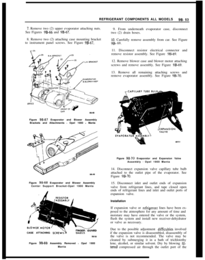
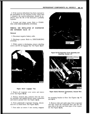
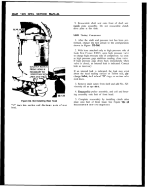
7C-1281973 OPEL SERVICE MANUAL2. Insert third clutch drum and input shaft through
top of second clutch drum seating third clutch drum
splines into the second clutch plate splines. See Fig-ure x2- 212.
Figure 7C-2 123. Holding second and third clutch assemblies by the
input shaft, lower into transmission case, indexing
ring gear in second clutch drum with long planetary
pinion gear teeth. See Figure
7C-213..----INPUT
SHAFTInstallation of Reverse Clutch
1. Inspect condition of the composition and steel
;:;;;.Do not diagnose a composition drive plate by
A. Dry composition plates with compressed air and
inspect the composition surface for:
1. Pitting and flaking
2. Wear
3. Glazing
4. Cracking
5. Charring
6. Chips or metal particles imbedded in lining
If a composition drive plate exhibits any of the above
conditions, replacement is required.
B. Wipe steel plates dry and check for heat discolora-
tion. If the surface is smooth and an even color smear
is indicated, the plates should be reused. If severe
heat spot discoloration or surface scuffing is in-
dicated, the plates must be replaced.
2. Install the steel reaction plate into the case. See
Figure 7C-214.
Figure 7C-2 143. Install reverse clutch steel plate, composition
plate, steel plate, composition plate, etc., into case.
Use a liberal amount of transmission fluid.
Figure 7C-213
Page 490 of 625

AUTOMATIC TRANSMISSION 7C-129
4. Install reverse clutch cushion plate (wave washer)2. Insert guide pin into oil pump for alignment of
into case.converter housing and lower housing onto pump.Determining Selective Washer Size
1. Place gauging tool J-23085 on case flange andagainst input shaft. See Figure
7C-215.3. Install new oil seal washers on converter housing
to oil pump bolts, and loosely install bolts into con-
verter housing.
4. Use convkrter housing to oil pump aligning tool J-23082 to align converter housing to pump. See Fig-
ure
7C-216. Tool should bottom on oil pump gear.
Figure 7C-2 152. Loosen thumb screw on tool to allow inner shaft
to drop on second clutch drum hub.
3. Tighten thumb screw and remove tool J-23085.
4. Place selective washer removed from transmission
against inner shaft of tool J-23085. Selective washer
should be flush with top face of shaft. If not flush,
select next larger or smaller washer until correct size
is obtained. The washer selected should be exactly
flush or slightly below inner shaft for correct end
play in transmission. Selective washer removed from
transmission may be oil soaked and discolored.
CObX
ID
Yellow
Blue
Red
BVSNIl
GPX3”
Black
Thickness,070.,074,076.,080
.08 l-.085,086.,090,091.,095
,097.,101
Installation of Converter Housing, Oil Pump and
Reverse Clutch Assembly1. Turn case so that bottom of transmission is facing
upward.
1. Install oil pump wear plate onto oil pump.2. Slide governor hub along output shaft and seat
Figure 7C-2 165. Tighten the five bolts. Torque to
13-17 Ibs. ft. and
remove aligning tool l-23082.
6. Install new converter housing to case rubber oil
seal.7. Install new pump flange gasket.
8. Place selective washer, previously determined,
onto the oil pump shaft and retain with petroleum
jelly (unmedicated).
9. Install two guide pins in case and lower converter
housing and oil pump into case. See Figure
7C-217.10. Bolt converter housing to case using new oil seal
washers on all seven bolts. Torque to 13-17 lbs. ft.
I I. Check for correct assembly by turning input shaft
by hand.
Installation of Governor Assembly
Page 491 of 625
7C-130
1973 OPEL SERVICE MANUAL
Figure 7C-2 17
into case. See Figure 7C-218. Use liberal amount of
transmission fluid on oil seal rings.
GOVERNOR
HUBFigure
7C-2 183. Install snap ring over output shaft using snap ring
pliers such as J-8059. See Figure
7C-219.4. Install new governor body gasket.
5. Bolt governor body to governor hub. Torque to 6-8
lbs. ft. The two governor valves should move freely
after governor body is torqued.
6. Install speedometer drive gear retaining clip into
output shaft. See Figure
7C-220.Figure 7C-219
Figure 7C-220
7. While depressing retaining clip, slide speedometer
gear over output shaft and install gear and retaining
clip.
Installation of Extension Housing
1. Install new extension housing gasket.
2. Slide extension housing over output shaft and
align holes.
3. Align parking
paw1 shaft into extension housing.
Page 492 of 625

AUTOMATIC TRANSMISSION 7C-1314. Bolt extension housing to rear of case. Torque to
20-30 Ibs. ft. See Figure
7C-221.
Figure 7C-22
1
Installation of Speedometer Driven Gear1. Install speedometer driven gear and housing into
extension housing. See Figure
7C-222.Figure 7C-222
2. Install speedometer driven gear housing retainer
into slot provided in speedometer driven gear hous-
ing. Bolt retainer to extension housing. Torque to
6-Slbs. ft. See Figure
7C-223.
installation of Detent Valve, Modulator Valve,
Modulator Assembly1. inspect detent valve sleeve oil seal and replace if
necessary.Figure 7C-223
2. Install detent valve, sleeve, spring, and spring seat
into case bore using liberal amount of transmission
fluid.
3. Depress detent valve spring and insert spring pin
to secure detent valve assembly. Detent valve sleeve
must be installed with slots facing oil pan. Care
should be taken so that spring pin is inserted into the
groove provided in sleeve and not into one of the oil
passage slots in the sleeve.
4. Install modulator valve and sleeve into case with
small end of modulator valve first.
5. Using new modulator assembly gasket, install
plunger and thread modulator into case and tighten
to
12-15 Ibs. ft. using tool J-23100. See Figure 7C-
224.
Installation and Adjustment of ServoAdjustment of servo can be performed with trans-
mission in vehicle.
1. Install servo apply rod, spring and piston into case,
using liberal amount of transmission fluid.
2. Compress servo piston spring using compressor
tool J-23075, lightly tapping servo piston while com-
pressing until piston is seated to avoid damage to the
oil seal ring.
3. Install servo retaining ring. See Figure
7C-225.Remove compressor tool J-23075.
Page 493 of 625
7C-1321973 OPEL SERVICE MANUAL
Figure 7C-226
Figure 7C.224
Figure 7C-225
4. Using 3/16” hex head wrench on servo adjusting
bolt, adjust servo apply rod by tightening adjusting
bolt to 40 lbs. in. Back off bolt five (5) turns. exact/u.See Figure
7C-226.5. Tighten lock nut holding adjusting bolt and sleeve
firm with hex head wrench. See Figure
7C-227.
installation of Valve Body
1. I&all steel balls in oil passages in case. See Figure
7C-228.Figure 7C-227
2. Install new case to transfer plate gasket.
3. Locate guide pins in transmission case for correct
alignment of valve body and transfer plate. See Fig-
ure
7C-229.4. Install manual valve into valve body bore using
liberal amount of transmission fluid.
5. Install long side of manual valve link pin into
manual valve. See Figure
7C-230.
Page 494 of 625
AUTOMATIC TRANSMISSION 7C-1338/Figure 7C-228
Figure 7C-229
6. Install small end of manual valve link “A” into
selector lever and install valve body and transfer
plate assembly over guide pins. See Figure
7C-23 1.
7. Install selector lever roller spring and retainer.
Torque to
13-15 lbs. ft. The valve body bolts should
be torqued starting in the center of the valve body
and working outward. Torque to 13-15
lbs. Ft.
8. Install reinforcement plate to case. Torque to
13-15 lbs. ft.9. Inspect oil strainer. If foreign matter is present,
install new strainer.
-VALV; BODY
x-220
Figure 7C-230
Figure
7C-231
10. Install oil strainer assembly using new gasket.
Torque to 13-15 Ibs. ft.
11. Install new servo cover gasket.
12. Install servo cover. Torque to 17-19 lbs. ft.
Installation of Oil Pan and Gasket1. Install new oil pan gasket.
2. Bolt oil pan to transmission case. Torque to 7-9
lbs. ft.
Page 495 of 625

7C-1341973 OPEL SERVICE MANUAL
Figure 7C-232
Torque Converter4. Rotate converter to check for free movement.
1. Place transmission on portable jack
2. Slide torque converter over stator shaft and input
shaft.3. Be sure that converter pump hub keyway is seated
into oil pump drive lugs and the distance “A” is
.20”to
.28”. See Figure 7C-232.
SPECIFICATIONS
GENERAL SPECIFICATIONS
Opel Three-Speed Automatic Transmission Fluid
RecommendationsUse DEXRON Automatic Transmission Fluid on/y
in all 1972 model Opel Automatic Transmissions
(GM part No. 1050568-69-70 or any other fluid hav-
ing DEXRON identifications).DEXIRON is an especially formulated automatic
transmission fluid designed to improve transmission
operation.
The oil pan should be drained and the strainer re-
placed every
24,ooO miles and fresh fluid added to
obtain the proper level on the dipstick. See subpara-
graph 2 for proper refill procedures. For cars sub-
jected to heavy city
traff%z during hot weather, or in
commercial use, when the engine is regularly idled
for long periods, the oil pan should be drained and
the strainer replaced every
12,ooO miles.
.
1.Checking and Adding FluidThe Opel three-speed automatic is designed to oper-
ate at the full mark on the dipstick at normal operat-
ing temperature (180 degrees F.) and should be
checked under these conditions. The normal operat-
ing temperature is obtained only after at least 15
miles of highway type driving or the equivalent of
city driving.
Fluid level should be checked at every engine oil
change.
The “FuIl” and “Add” marks on the trans-
mission dipstick indicate one (1)pint
difference. Todetermine proper fluid level, proceed as follows:
To determine proper level, proceed as follows:
1. With manual control lever in Park position start
engine. DO NOT RACE ENGINE. Move manual
control lever through each range.
2. Immediately check fluid level with selector lever
in Park, engine running, and vehicle on LEVEL
surface.At
t,his point, when a reading is made, fluid level on
the dipstick should be at the “FULL” mark.
3. If additional fluid is required, add fluid to the
“FULL” mark on the dipstick.
If the vehicle cannot be driven sufficiently to bring
the transmission to operating temperature and it
Page 496 of 625

AUTOMATIC TRANSMISSION 7C-135
becomes necessary to check the fluid level, the trans-
mission may be checked at room temperature (70
degrees F.) as follows:
1. With manual control lever in Park position start
engine. DO NOT RACE ENGINE. Move manual
control lever through each range.
2. lmmediately check fluid level with selector lever
in Park, engine running, and vehicle on LEVEL sur-
face.At this point, when a reading is made, fluid level on
the dipstick should be I/4” below the “ADD” mark.
3. If additional fluid is required add fluid to bring
level to
l/4” below the “ADD” mark on the dip-
stick.If transmission fluid level is correctly established at
70 degrees F. it will appear at the “FULL” mark on
the dipstick when the transmission reaches normal
operating temperature (180 degrees F.) The fluid
level is set
l/4” below the “ADD” mark on the
dipstick to allow for expansion of the fluid which
occurs as transmission temperatures rise to normal
operating temperature of 180 degrees F.
Do not overfill, as foaming and loss of fluid through
the vent pipe might occur as fluid heats up. If fluid
is too low especially when cold, complete loss
of’drive may result which can cause transmission fail-
ure.
2.Draining oilpan and rep/a&g strainer assembly.
(a) Raise car on hoist or p/ace OnJxk stands, and
provide container to collect draining fluid.
(b) Remove oil pan and gasket. Discard gasket.
(c) Drain fluid from oil pan. Clean pan with solvent
and dry thoroughly with clean compressed air.
(d) Remove strainer assembly, strainer gasket and
discard.
(e) Install new oil strainer gasket. Install new strainer
assembly.
(f) Install new gasket on oil pan and install pan.
Tighten attaching bolts to 7-10 lb. ft.
(g) Lower car and add approximately three (3) pints
of transmission fluid through filler tube.
(h) With manual control lever in Park position, start
engine. DO NOT RACE ENGINE. Move manual
control lever through each range.
(i) Immediately check fluid level with selector leverin Park, engine running, and vehicle on LEVEL
sur-
face.(i) Add additional fluid to bring level to
l/4” below
the “ADD” mark on the dipstick. Do not overfill.
3.Adding Fluid to Fill Dry Transmission and Con-
verter Assembly
The fluid capacity of the Opel Three Speed Auto-
matic transmission and converter assembly is ap-
proximately IO-l/2 pints, but correct level is
determined by the mark on the dipstick rather than
by amount added. In cases of transmission overhaul,
when a complete fill is required, including a new
converter proceed as follows:
(a) Add approximately 10-l/2 pints of transmission
fluid through tiller tube.
The converter should be replaced on any major fail-
ure, such as a clutch or gearset, and an excessive
amount of foreign material is indicated in the pan. If
installation of a new converter is not required add
approximately five (5) pints of transmission fluid.
(b) With manual control lever in Park position start
engine and run at 1000 RPM. DO NOT RACE EN-
GINE. Move manual control lever through each
range.
(c) Immediately check fluid level with selector lever
in Park, engine running, and vehicle on LEVEL
sur-
face.(d) Add additional fluid to bring level to
l/4” below
the “ADD” mark on the dipstick. Do not overfill.
Opel Three Speed Automatic Transmission Towing
Instructions
If an Opel equipped with an automatic transmission
must be towed, the following precautions must be
observed:
The car may be towed safely on its rear wheels with
the shift lever in neutral position at speeds of 35 miles
per hour or less under most conditions.
However, the drive shaft must be disconnected or the
car towed on its front wheels if:
a. Tow speeds in excess of 35 mph are necessary.
b. Car must be towed for extended distances (over 50
miles).
c. Transmission is not operating properly.
If car is towed on its front wheels, the steering wheel