Page 177 of 625

3A- 101973 OPEL SERVICE MANUAL
Figure 3A-18 Lower Ball Joint Notch Opel 1900 -
MantaUPPER CONTROL ARM REMOVAL AND
INSTALLATION
Removal GT1. Raise car and support at rear of front frame rails.
2. Remove front wheel.
3. Install spring compressor and compress spring
until there is 3-l/8” between compressor and lower
spring leaf.
4. Remove cotter pin and castle nut from upper ball
joint stud. Discard cotter pin.
5. Use tie rod remover J-21687 remove ball jointfrom.steering knuckle. 6. Support brake drum to
relieve tension on brake hose.
7. Remove hex nut from upper control arm shaft.
Remove shaft and washers from shock absorber sup
port. Do not damage threads on control arm shaft.
8. Remove control arm from car. Do not lose inner
toothed washers. Note size and location of toothed
washers.Removal
Opel 1900 . Manta
1, Raise car and support at rear of front frame rails.
2. Remove front wheel
3. Unscrew upper control arm to cross member
self-locking attaching nut.4. Unscrew ball joint from upper control arm. Do not
turn upper control arm ball joint flange, as this
would result in a change of camber.
5. Support front wheel hub so that brake hose is not
stressed.6. Pull out upper control shaft to cross member at-
taching bolt and remove control arm. Shims have to
be reinstalled in their original location to maintain
the proper caster setting.
Installation GT
CAUTION:
Fasteners are important attaching parts in
that they could affect the the
perfonmmce of vital
components and systems, and/or could result in ma-
jor repair expense. They must be replaced with one
of the same part number or with an equivalent part
if replacement becomes necessary. Do not use a re-
placement part or lesser quality or substitute design.
Torque values must be used as specified during reas-
sembly to
assure proper retention of these parts.If rubber bushings on control arms are worn, arms
must be replaced.
1. Slide rubber rings over bushings. Slide rings over
inner sleeves of bushings. Place control arm in posi-
tion on shock absorber support, installing toothed
washers in their original positions. See Figure 3A-
19.2. From front to rear, install control arm shaft. If
necessary, align washers and control arm bushings
with a small drift prior to installing control arm
shaft. See Figure
3A-19.3. Tighten hex nut on control arm shaft finger tight.
4. Increase tension on spring compressor in order to
relieve tension on control arm shaft. Then torque hex
nut on control arm shaft to 33
Ib.ft.5. Press ball joint stud into steering knuckle and
torque castle nut to 29 lb.ft. Install new cotter pin.
6. Remove spring compressor and lower car.
7. Check front end alignment.
Installation Opel 1900. Manta
CAUTION:
Fasteners are important attaching parts in
that they could at?&
the performance of vital com-
ponents and systems, and/or
coo/d result in major
repair expense. They must be replaced with one of
the same part number or with equivalent parts, if
replacement becomes necessary. Do not use a
re-
Page 178 of 625

FRONT SUSPENSION3A- 11UPPER CONTROL ARM SHAFT
INNER SLEEVE
OUTER SLEEVE
RUBBER DAMPENIN
GUIDE SLEEVE
ABSORBER SUPPOR
SHOCK ABSORBER SUPPORT
ON FRONT SUSPENSION
CROSS MEMBER
-TOOTHED WASHER
l-UPPER CONTROL ARM
RUBBER BUSHINGS
PLATE WASHER
Figure
3A-19 Upper Control Arm Shaft and Bushings
placement part of lesser quality or substitute design.
Torque
valves must be used as specified during reas-
semb/y to assure proper retention of these parts.1. On installation of the upper control arm, make
sure that damper bushing with the rubber shoulder
on both sides is always located in the rear.
2. Attach upper control arm to cross member and
torque to
40 lb.ft. Always use new self-locking hex
nut. The upper control arm must be tightened in
horizontal position only. This applies also to all other
attaching joints in connection with rubber damper
bushings in the control arms of the front suspension
so that the rubber parts under load are in an almost
twist-free condition. This position exists, if the hooks
J-23697 are used.
3. Attach ball joint to upper control arm and torque
to 29
lb.ft.4. Install wheel and torque nuts to 65
lb.ft. Lowercar.LOWER CONTROL ARM REMOVAL AND
INSTALLATION
Removal GT
1. Raise car and support at rear of front frame rails.
2. Remove front wheel.
3. Remove cotter pin from castle nut on ball joint
stud and back off castle nut two (2) turns. Hit ball
stud a sharp blow to break it loose. DO NOT
REMOVE NUT.
4. Install spring compressor (J-21689) and compress
spring until a distance of
3-l/8 inches is achieved
between spring compressor and lower spring leaf.
5. Disconnect and compress shock absorber.
6. Support rail of spring compressor with a jack.
Remove lower control arm from frame cross mem-
ber. Nuts may have to be removed with a punch. See
Figure 3A-20. Discard the lock nuts.
7. Remove lower ball joint stud nut. Slightly lower
Page 179 of 625

3A- 121973 OPEL SERVICE MANUAL
Figure 3A-20 Lower Control Arln Attachment
jack so that spring and lower control arm assembly
is removed from the front cross member and steering
knuckle.
8. Lower jack, spring compressor, and front spring
with control arm assembly. Remove lower control
arm to spring nuts.
9. Release spring compressor and remove controlarm attaching bolts and control aRn.
Removal Opel 1900. Manta1. Prior to raising car, install upper control arm
hooks J-23697.
2. Raise car and support with stands. Hoist should
be left in the raised position to maintain pressure on
lower control arm.
3. Remove front wheel.
4. Detach both stabilizer supports from cross mem-
ber to body support.
5. In lower control arm, remove self-locking hex
head bolt from stabilizer support and remove
washer.6. Using a pry bar, pry stabilizer bar out of lower
control arm support.
7. Remove shock absorber.
8. At lower control arm ball joint, remove castle nut
cotter pin and remove nut.
9. With suitable drift, detach lower control arm ball
joint from steering knuckle.10. Loosen nut that retains lower control to front
cross member.
11. Slowly lower hoist to release spring tension.
12. Swing lower control arm downwards and remove
front spring.13. Remove nut that retains lower control arm to
front cross member and remove lower control arm.
Installation GT
CAUTION:
Fasteners are important attaching parts in
that they could affect the performance of
vital com-
ponents and systems, and/or could result in
major
repair expeme. They must be replaced with one of
the
same part number or with an equivalent part if
replacement becomes necessary. Do not use a re-
placement part of
lesser quality or substitute design.
Torque values must be used as specified during
reas-
sembly to assure proper retention of these parts1. Attach lower control arm to front spring eye.
Torque bolts to 18
1b.R.2. Install spring compressor and with a jack raise
spring compressor with spring and control arm as-
sembly into position for pressing ball joint into steer-
ing knuckle.
3. Press ball joint into steering knuckle. Use
J-;lYN;: as installer and J-21690 as a supporting
4. Install castle nut on ball joint stud and torque to
54
lb.ft. Install new cotter pin.
5. Attach lower control arm to frame cross member
using new lock nuts.
Page 180 of 625

FRONT SUSPENSION3A- 13
6. Reconnect shock absorber to lower control arm
and torque to 30
Ib.ft.7. Remove spring compressor.
8. Install front wheel, and lower the car.
9. Check front end alignment.
Installation Opel 1900 Manta
CAUTION: Fasteners are important attachingparts in
that they could aff&
the-performance of vitaI com-
ponents and systems, and/or could
resu/t in major
repair expenses. They must be
repraced with one of
the same part number or with an
equivaknt part, ifreplacement becomes necessary. Do not use a re-
placement part of ksser quality or substitute design.
Torque values must be used as specified
dmitig reas-
sembIy to assure proper retention of these parts.1. Loosely attach lower control arm to front cross
member.
2. Properly seat spring between lower control arm
and cross member.
3. Raise jack and place lower control into position.
4. Attach lower control ball joint to steering knuckle
and torque nut to 54
Ib.ft.5. Tighten lower control arm to cross member bolt
to 43
lb.ft.6. Attach stabilizer bar to lower control arm and
torque to 87
lb.ft.7. Attach stabilizer bar to cross member to body
support.
8. Install shock absorber and torque lower attaching
nut and bolt to 30
lb.ft.9. Install nuts on upper shock absorber attaching
studs. Tighten nuts until a distance from top of nut
to stud is approximately
l/2 inch.
10. Install front wheels and tighten nuts to 65
lb.ft.11. Remove stands and lower car.
STEERING KNUCKLE REMOVAL AND
INSTALLATION
Removal GT1. Raise car and support with stands.
2. Remove wheel nuts. Remove wheel assembly.
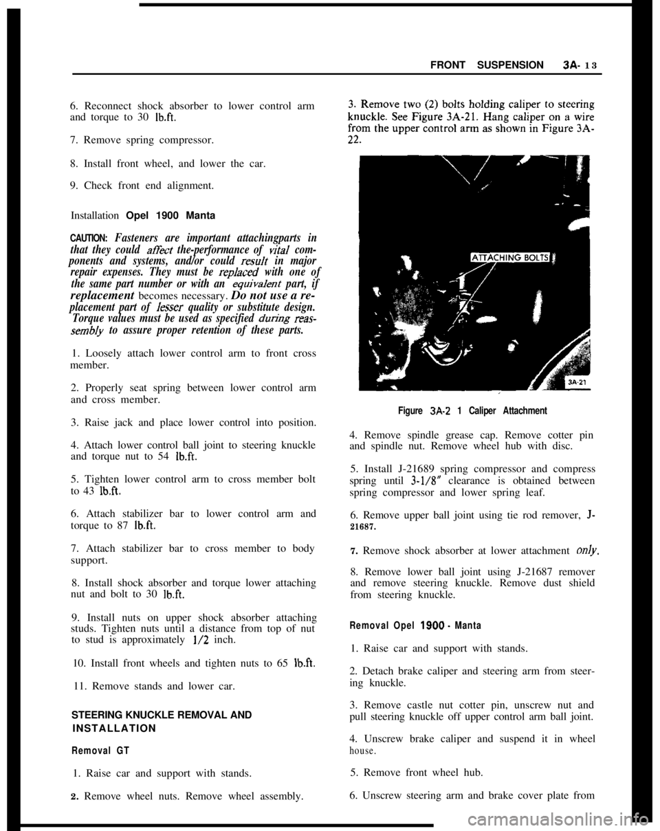
Figure 3A-2 1 Caliper Attachment4. Remove spindle grease cap. Remove cotter pin
and spindle nut. Remove wheel hub with disc.
5. Install J-21689 spring compressor and compress
spring until 3-l/8” clearance is obtained between
spring compressor and lower spring leaf.
6. Remove upper ball joint using tie rod remover,
J-
21687.7. Remove shock absorber at lower attachment only.
8. Remove lower ball joint using J-21687 remover
and remove steering knuckle. Remove dust shield
from steering knuckle.
Removal Opel 1900. Manta1. Raise car and support with stands.
2. Detach brake caliper and steering arm from steer-
ing knuckle.
3. Remove castle nut cotter pin, unscrew nut and
pull steering knuckle off upper control arm ball joint.
4. Unscrew brake caliper and suspend it in wheel
house.5. Remove front wheel hub.
6. Unscrew steering arm and brake cover plate from
Page 181 of 625

3A. 141973 OPEL SERVkE MANUAL
Figure 3A-22 Caliper Removed and Hung by Wire
steering knuckle. Swing steering arm and tie rod to
the side.7. Remove castle nut cotter pin, unscrew nut and
pull steering knuckle off lower control arm ball joint.
Installation GTCAUTION: Fasteners are important attachingparts in
that they could affect the performance of
viral com-
ponents and systems, and/or could result in major
repair expense. They must be replaced with one of
the same part number or with an equivalent part if
replacement becomes necessary. Do not use a re-
placement part of lesser quality or substitute
desig.Torque values must be used as specified during reas-
sembly to assure proper retention of these parts.
1. Always replace paper gasket when installing dust
shield on steering knuckle. Lightly coat both surfaces
of paper gasket with chassis lubricant before installa-tion and torque attaching bolts to 47
lb.ft.2. Install lower ball joint in steering knuckle. Torque
castle nut to 54
Ib.ft. Install new cotter pin.
3. Attach shock absorber at lower end. Torque boltsto 30 lbs. ft.
4. Install upper ball joint. Torque castle nut to 29
lb.ft. Install new cotter pin.
5. Remove spring compressor.6. Install hub and disc on spindle and tighten spindle
nut as stated under MAINTENANCE AND AD-
JUSTMENTS in this section.
7. Install caliper on steering knuckle and torque boltsto 72
lb.ft. See Figure 3A-21.8. Install wheel and torque wheel nuts to 65
lb.ft.
Installation Opel 1900
- MantaCAUTION: Fasteners are important attachingparts in
that they could
affit the performance of vital com-
ponents and systems, and/or could result in
ma&repair expense. They must be replaced with one of
the same part number or with equivalent parts, ifrepfacement becomes necessary. Do not use a re-
placement part of lesser quality or substitute design.
Torque values must be used as specified during reas-
sembly to assure proper retention of these parts.
1. Attach steering knuckle to lower control arm ball
joint. Torque castle nut to 54
lb.ft.
2.
Atl,ach brake cover plate and steering arm to steer-ing knuckle. If required, install new paper gasket
between cover plate and steering knuckle. Care for
proper seat of T-head bolts. See Figure
3A-23.Figure 3A-23 Attaching Brake Cover Plate
3. Install front wheel hub and brake caliper.
4. Attach steering knuckle to upper control arm ball
joint. Torque castle nut to 40
lb.ft.5. Steering arm to steering knuckle
_ 58 lb.ft.6. Brake caliper to steering knuckle
- 72 lb.ft.7. Adjust front wheel bearing clearance.
8. Remove stands and lower car
Page 182 of 625

FRONT SUSPENSION3A- 15
SHOCK ABSORBER REMOVAL ANDINSTALLATION
Removal
Opel 1900. Manta1. Raise car and support with stands.
2. Remove upper attaching nuts from shock ab-
sorber.3. Remove lower attaching nut, lockwasher, and
bolt.
4. Compress shock absorber and remove from car.
Removal GT1. Remove air cleaner. See Figure 3A-24.
Figure 3A-24 Removal of Air Cleaner
2. Remove plastic cover over shock absorber upper
attachment.
3. Raise car and support with stands.
4. Remove upper attaching nuts from shock ab-
sorber.5. Remove lower attaching nut, lockwasher, and
bolt.
6. Compress shock absorber and remove from car.
Installation Opel 1900. Manta1. Inspect shock absorber for damage and seal leaks.Always replace the upper and lower rubber grom-
mets when replacing a shock absorber.
2. Install the lower grommet retainer and grommets
on shock absorber. Compress shock absorber and
place in position.
3. Install lower attaching bolt and nut. Torque to 30
lb.ft.4. Install nuts on upper attaching studs. Tighten nuts
until distance from top of nut to stud is approxi-
mately
l/2 inch. See Figure 3A-25.5. Install plastic cover.
Installation GT1. Inspect shock absorber for damage and seal leaks.
Always replace the upper and lower rubber grom-
mets when replacing a shock absorber.
2. Install the lower grommet retainer and grommets
on shock absorber. Compress shock absorber and
place in position.
3. Install lower attaching bolt and nut. Torque to 30
lb. ft.
4. Install nuts on upper attaching studs. Tighten nuts
until distance from top of nut to stud is approxi-
mately
l/2 inch. See Figure 3A-25.5. Install plastic cover.
6. Install air cleaner.
FRONT SPRING REMOVAL AND INSTALLATION
Removal (GT)1. Raise car and support at rear of front frame rails
with stands.
2. Remove front wheels.
3. Remove cotter pin from castle nut on lower ball
joint studs and back off castle nut two (2) turns. Hit
ball stud a sharp blow to break it loose. Do not
remove nut.4. Install J-21689 spring compressor and compress
the spring until 3-l/8” clearance is obtained between
spring and compressor.
5. Disconnect both shock absorbers at their lower
attachment. Compress both shock absorbers.
6. Support the rail of J-21689 Spring Compressor
with a jack. Remove lower control arm to cross
member attaching nuts and bolts.
Page 183 of 625

3A- 161973 OPEL SERVICE MANUAL
INNER RUBBERSTUD.1 /2”\E
/
PLASTIC COVER
DAMPENING RING
RETAINERRUBBER DAMPENING RING-
-zSELF-LOCKING NUT
UPPER RUBBER
GROMMET RETAINERLOWER
RUBIGROMMET RETAINER
WHEEL HOUSE
SHOCK ABSORBER
SHOCK ABSORBERSA-25Figure
3A-25 Shock Absorber Upper Attachment
7. Remove lower ball joint stud nuts. Slightly lower
jack so that the spring and lower control arm assem-
bly is removed from the front cross member and
steering knuckle.
8. Lower jack, spring compressor, and front spring
and control arm assembly. Remove lower control
arm to spring nuts.
9. Relieve tension on spring compressor and remove
control arm attaching bolts and control arms.
Removal (Opel 1900 - Manta)1. Prior to raising car, install upper control arm
hooks J-23697.
2. Raise car and stipport with stands. Hoist should
be left in the raised position to maintain pressure on
lower control arm.
3. Remove front wheel.
4. Detach both stabilizer supports from cross mem-
ber to body support.5. Remove shock absorber.
6. At lower control arm ball joint, remove castle nut
cotter pin and remove nut.
7. With suitable drift, detach lower control arm ball
joint from steering knuckle.
8. Loosen nut that retains lower control to front
cross member.
9. Slowly lower hoist to release spring tension.
10. Swing lower control arm downwards and remove
front spring.
Installation (GT)
CAUTION:
Fasteners are important attachingparts in
that they could at&t
the performance of vital com-
ponents and systems, and/or could result in major
repair expense. They must be replaced with one of
the same part number or with an equivalent part if
replacement becomes necessary. Do not use a
re-
placement part oflesser quality or substitute design.
Page 184 of 625

FRONT SUSPENSION3A- 17Torque values must be used as specified during reas-
sembly to assure proper retention of these parts.1. Attach lower control arm to front spring eye.
Torque bolts to 18
lb.ft.2. Install spring compressor on spring and compress
spring to appropriate length.
3. Raise jack with spring compressor, spring and
control arm assembly into position under the car.
4. Install lower ball joints and torque nuts to 54
Ib.ft.Install new cotter pin.
5. Attach lower control arms to frame cross member
using new lock nuts.
6. Attach both shock absorbers. Torque bolts to 30
lb.ft.7. Remove spring compressor.
8. Install front wheels.
On replacement of the damper bushings on the front
springs, only the one-part damper bushing is in-
stalled for either the two-leaf or three-leaf spring.
For proper location of the marking lugs, see Figure3A-26.
Installation (Opel 1900. Manta)
CAUTION: Fasteners are important attachingparts in
that they
co&d affect the performance of vital com-
ponents and systems, and/or could result in major
repair expense. They must be replaced with one of
the same part number or with an equivalent part, if
replacement becomes necessary. Do not use a re-
placement part of
lesser quality or substitute design.
Torque values must be used as specified
during reas-
sembly to assure proper retention of these parts.1. Properly seat spring between lower control arm
and cross member.
2. Raise jack and place lower control into position.CROSS SECTION
SA-26Fig. 3A-26 Front Spring Damper Bushing.
3. Attach lower control ball joint to steering knuckle
and torque nut to 54
lb.ft.4. Tighten lower control arm to cross member bolt
to 43 lb.ft.
5. Attach stabilizer bar to cross member to body
support.
6. Install shock absorber and torque lower attaching
nut and bolt to 30
lb.ft.7. Install nuts on upper shock absorber attaching
studs. Tighten nuts until a distance from top of nut
to stud is approximately
l/2 inch.
8. Install front wheels and tighten nuts to 65
lb.ft.9. Remove stands and lower car.
SPECIFICATIONSBOLT TORQUE AND FRONT END ALIGNMENT