1973 DATSUN B110 wheel bolts
[x] Cancel search: wheel boltsPage 162 of 513

Iii
I
o
t
I
I
CHASSIS
Fig
ST
2
Steering
wheel
REMOVAL
1
Remove
the
horn
ring
and
remove
the
steering
wheel
nut
and
pull
out
the
steering
wheel
by
the
use
of
a
Steer
ing
wheel
puller
ST27180000
3
Remove
the
turn
signal
and
lighting
switch
com
pletely
4
Remove
the
hand
lever
assembly
from
the
control
rod
assembly
by
unscrewing
the
fIxing
bolts
5
Remove
two
fIxing
bolts
used
to
secure
the
steering
column
to
the
instrument
panel
ST27180000
Fig
ST
3
Removing
steering
wheel
lock
nut
Note
The
horn
ring
can
be
easily
removed
by
two
bolts
2
Remove
the
steering
column
shell
Fig
ST
4
Removing
steering
column
upper
side
ST
2
Page 166 of 513
I
CHASSIS
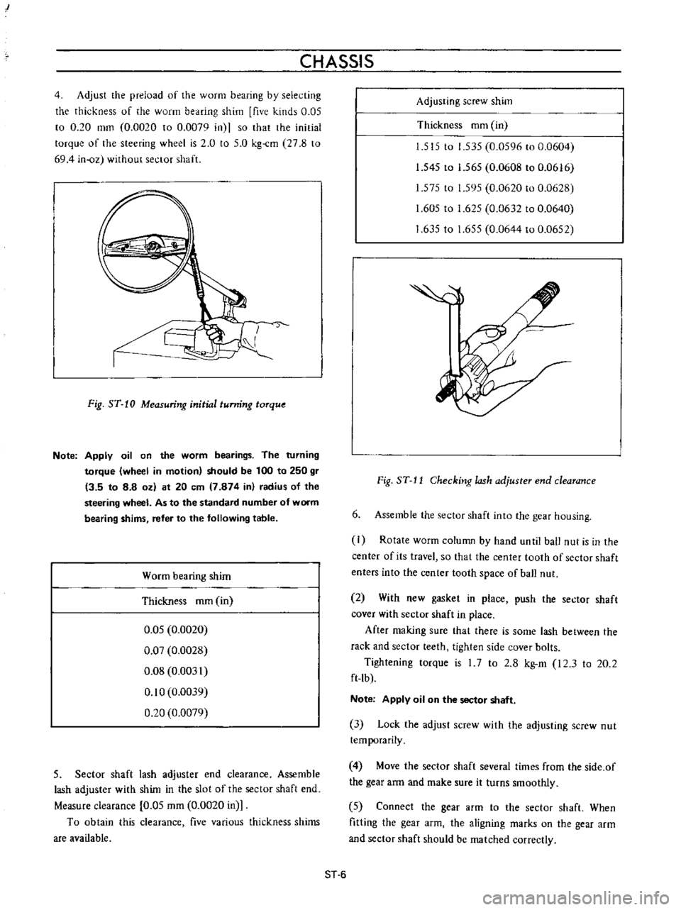
4
Adjust
the
preload
of
the
worm
bearing
by
selecting
the
thickness
of
he
worm
bearing
shim
five
kinds
0
05
to
0
20
mm
0
0020
to
0
0079
in
so
that
the
initial
torque
of
the
steering
wheel
is
2
0
to
5
0
kg
cm
27
8
to
694
in
oz
without
sector
shaft
J
Fig
ST
10
Measuring
initial
tunring
torque
Note
Apply
oil
on
the
worm
bearings
The
turning
torque
wheel
in
motion
should
be
100
to
250
gr
13
5
to
8
8
oz
at
20
em
7
874
in
radius
of
the
steering
wheel
As
to
the
standard
number
of
worm
bearing
shims
refer
to
the
following
table
Worm
bearing
shim
Thickness
mm
in
0
05
0
0020
0
07
0
0028
0
08
0
0031
0
10
0
0039
0
20
0
0079
5
Sector
shaft
lash
adjuster
end
clearance
Assemble
lash
adjuster
with
shim
in
the
slot
of
the
sector
shaft
end
Measure
clearance
0
05
mm
0
0020
in
To
obtain
this
clearance
five
various
thickness
shims
are
available
Adjusting
screw
shim
Thickness
mm
in
1
515
to
1
535
0
0596
to
0
0604
1
545
to
1
565
0
0608
to
0
0616
1
575
to
1
595
0
0620
to
0
0628
1
605
to
1
625
0
0632
to
0
0640
1
63510
1
655
0
0644
to
0
0652
Fig
ST
J
J
Checking
lash
adjuster
end
clearance
6
Assemble
the
sector
shaft
into
the
gear
housing
I
Rotate
worm
column
by
hand
unlil
ball
nut
is
in
the
center
of
its
travel
so
that
the
center
tooth
of
sector
shaft
enters
into
the
center
tooth
space
of
ball
nut
2
With
new
gasket
in
place
push
the
sector
shaft
cover
with
sector
shaft
in
place
After
making
sure
that
there
is
some
lash
between
the
rack
and
sector
teeth
tighten
side
cover
bolts
Tightening
torque
is
I
7
to
2
8
kg
m
I2
3
to
20
2
ft
lb
Note
Apply
oil
on
the
sector
shaft
3
Lock
the
adjust
screw
with
the
adjusting
screw
nut
temporarily
4
Move
the
sector
shaft
several
times
from
the
side
of
the
gear
arm
and
make
sure
it
turns
smoothly
5
Connect
the
gear
arm
to
the
sector
shaft
When
fitting
the
gear
arm
the
aligning
marks
on
the
gear
arm
and
sector
shaft
should
be
matched
correctly
ST
6
Page 172 of 513
CHASSIS
The
sliding
block
is
secured
on
the
steering
post
bracket
with
bolts
upper
half
of
the
steering
column
is
supported
on
the
bracket
and
thus
the
steering
post
clamp
is
installed
on
the
body
When
a
large
impact
is
applied
from
the
driver
side
the
plastic
pins
are
cut
off
and
leaving
the
sliding
block
in
the
steering
post
bracket
side
the
clamp
proper
is
disengaged
downward
together
with
the
jacket
tube
For
any
force
applied
from
front
direction
of
the
vehicle
the
steering
post
clamp
sliding
block
does
not
move
rearward
This
construction
is
called
One
way
slide
system
and
with
this
construction
projection
of
the
column
shaft
toward
the
driver
is
prevented
completely
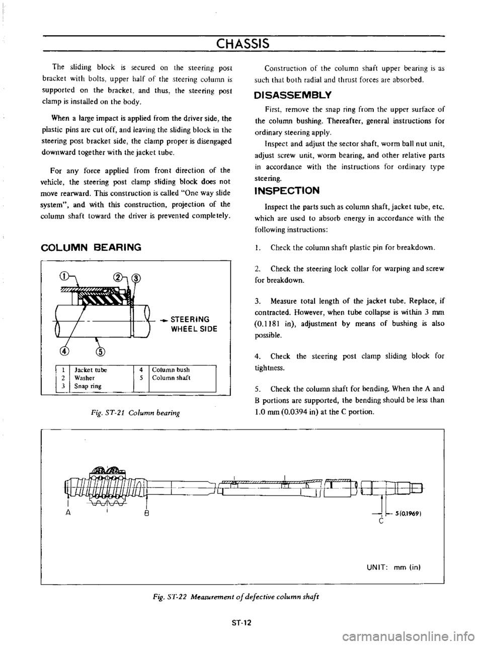
COLUMN
BEARING
b
ciJ
STEERING
WHEEL
SIDE
1
Jacket
tube
2
Washer
3
Snap
ring
4
Column
bush
5
ColurtlO
shaft
Fig
ST
21
Column
bearing
Construction
of
the
column
shaft
upper
bearing
is
as
such
that
both
radial
and
thrust
forces
are
absorbed
DISASSEMBLY
First
remove
the
snap
ring
from
the
upper
surface
of
the
column
bushing
Thereafter
general
instructions
for
ordinary
steering
apply
Inspect
and
adjust
the
sector
shaft
worm
ball
nut
unit
adjust
screw
unit
worm
bearing
and
other
relative
parts
in
accordance
with
the
instructions
for
ordinary
type
steering
INSPECTION
Inspect
the
parts
such
as
column
shaft
jacket
tube
etc
which
are
used
to
absorb
energy
in
accordance
with
the
following
instructions
Check
the
column
shaft
plastic
pin
for
breakdown
2
Check
the
steering
lock
collar
for
warping
and
screw
for
breakdown
3
Measure
tolal
length
of
the
jacket
tube
Replace
if
contracted
However
when
tube
collapse
is
within
3
mm
0
1181
in
adjustmenl
by
means
of
bushing
is
also
possible
4
Check
the
steering
post
clamp
sliding
block
for
tightness
5
Check
the
column
shaft
for
bending
When
the
A
and
B
portions
are
supported
the
bending
should
be
less
than
1
0
mm
0
0394
in
at
the
C
portion
I
l
j
B
H
I
I
lO
J
L
5
0
1969
C
J6
A
UNIT
mm
in
Fig
ST
22
Measurement
of
defective
column
shafr
ST
12
Page 177 of 513
STEERING
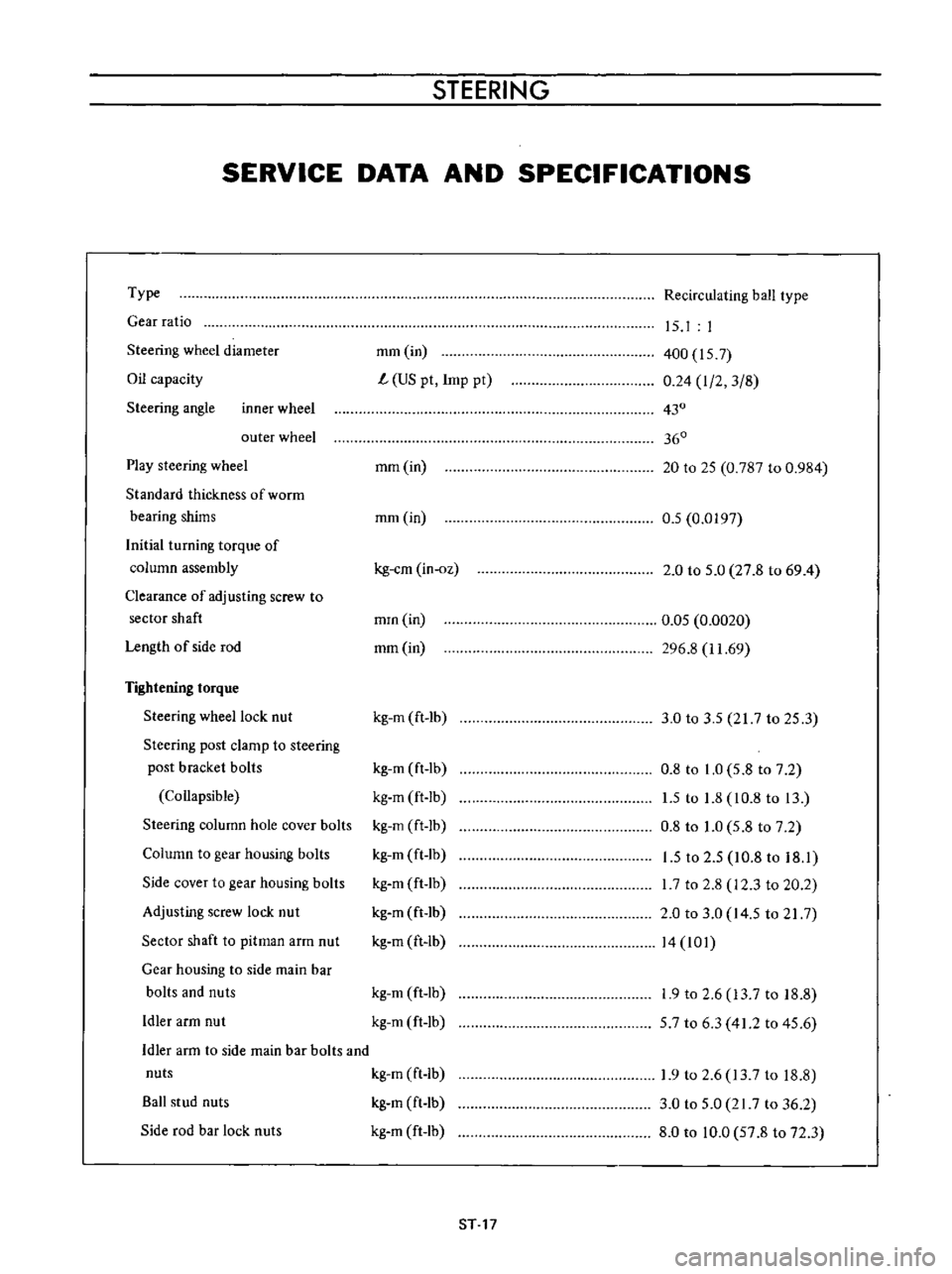
SERVICE
DATA
AND
SPECIFICATIONS
Type
Gear
ratio
Steering
wheel
diameter
Oil
capacity
Steering
angle
inner
wheel
outer
wheel
Play
steering
wheel
Standard
thickness
of
worrn
bearing
shims
Initial
turning
torque
of
column
assembly
Clearance
of
adjusting
screw
to
sector
shaft
Length
of
side
rod
Tightening
torque
Steering
wheel
lock
nut
Steering
post
clamp
to
steering
post
bracket
bolls
Collapsible
Steering
column
hole
cover
bolts
Column
to
gear
housing
bolts
Side
cover
to
gear
housing
bolts
Adjusting
screw
lock
nut
Sector
shaft
to
pitman
arm
nut
Gear
housing
to
side
main
bar
bolts
and
nuts
Idler
arm
nut
Recirculating
ball
type
mm
in
L
US
pt
Imp
pt
15
I
I
400
157
0
24
I
2
3
8
430
360
mm
in
20
to
25
0
787
to
0
984
mm
in
0
5
0
0197
kg
em
in
oz
2
0
to
5
0
27
8
to
69
4
mrn
in
mm
in
0
05
0
0020
296
8
11
69
kg
m
ft
lb
3
0
to
3
5
217
to
25
3
kg
m
ft
lb
kg
m
ft
Ib
kg
m
ft
lb
kg
m
ft
lb
kg
m
ft
lb
kg
m
ft
lb
kg
m
ft
lb
0
8
to
1
0
5
8
to
7
2
1
5
to
1
8
10
8
to
13
0
8
to
1
0
5
8
to
7
2
1
5
to
2
5
10
8
to
18
1
I
7
to
2
8
12
3
to
20
2
2
0
to
3
0
14
5
to
21
7
14
101
kg
m
ft
lb
kg
m
ft
lb
1
9
to
2
6
13
7
to
18
8
57
to
6
3
41
2
to
45
6
Idler
arm
to
side
main
bar
bolts
and
nuts
kg
m
ft
Ib
Ball
stud
nuts
kg
m
ft
lb
Side
rod
bar
lock
nuts
kg
m
ft
lb
1
9
to
2
6
13
7
to
18
8
3
0
to
5
0
21
7
to
36
2
8
0
to
10
0
57
8
to
72
3
ST
17
Page 178 of 513
CHASSIS
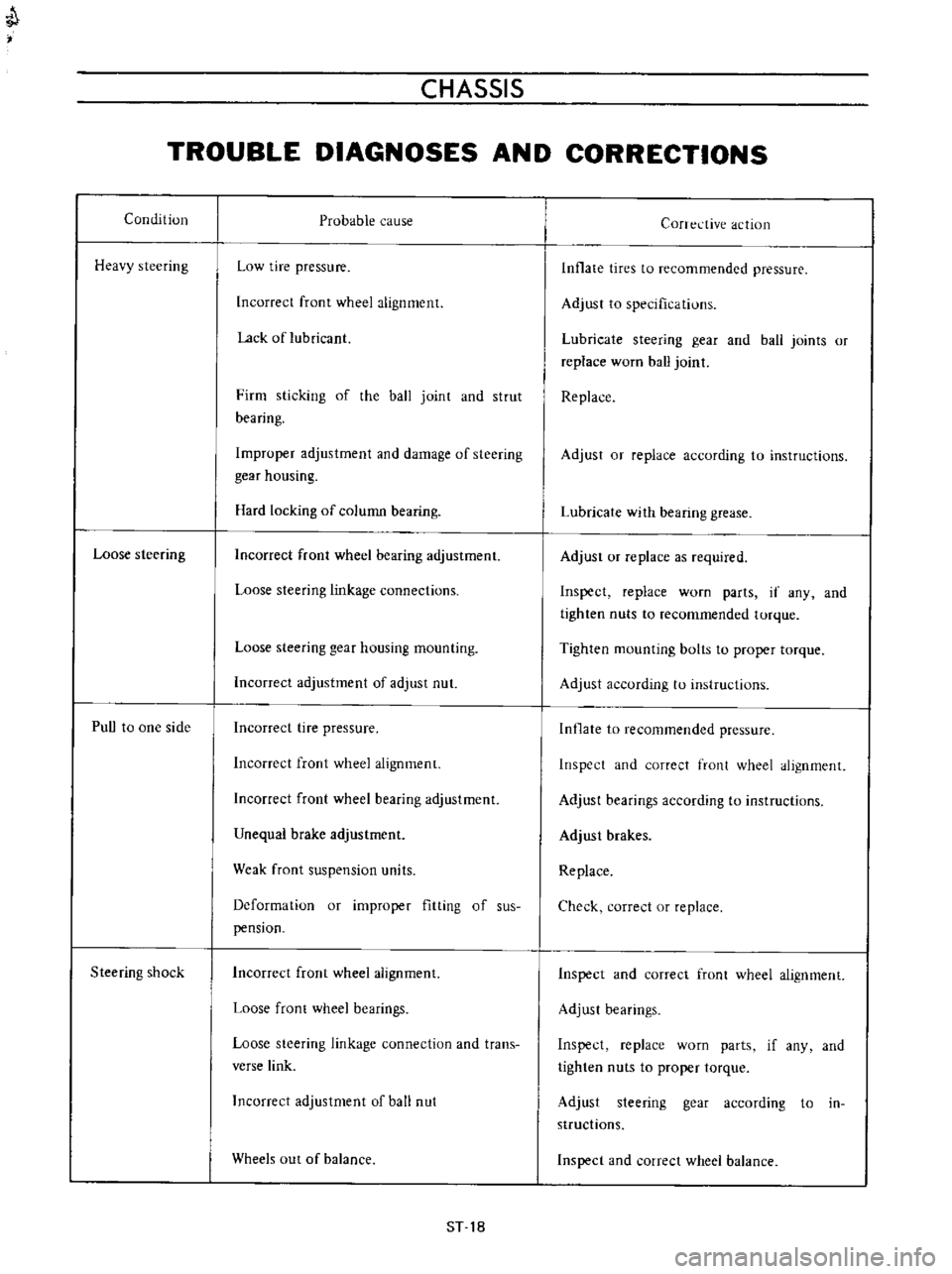
TROUBLE
DIAGNOSES
AND
CORRECTIONS
Condition
Heavy
steering
Loose
steering
PuU
to
one
side
Steering
shock
Probable
cause
Low
tire
pressure
Incorrect
front
wheel
alignment
Lack
of
lubricant
Firm
sticking
of
the
ball
joint
and
strut
bearing
Improper
adjustment
and
damage
of
steering
gear
housing
Hard
locking
of
column
bearing
Incorrect
front
wheel
bearing
adjustment
Loose
steering
linkage
connections
Loose
steering
gear
housing
mounting
Incorrect
adjustment
of
adjust
nut
Incorrect
tire
pressure
Incorrect
front
wheel
alignment
Incorrect
front
wheel
bearing
adjustment
Unequal
brake
adjustment
Weak
front
suspension
units
Deformation
or
improper
fitting
of
sus
pension
Incorrect
front
wheel
alignment
Loose
front
wheel
bearings
Loose
steering
linkage
connection
and
trans
verse
link
Incorrect
adjustment
of
ball
nut
Wheels
out
of
balance
ST
18
Corrective
action
Inflate
tires
to
recommended
pressure
Adjust
to
specifications
Lubricate
steering
gear
and
ball
joints
or
replace
worn
ball
joint
Replace
Adjust
or
replace
according
to
instructions
Lubricate
with
bearing
grease
Adjust
or
replace
as
required
Inspect
replace
worn
parts
if
any
and
tighten
nuts
to
recommended
torque
Tighten
mounting
bolts
to
proper
torque
Adjust
according
to
instructions
Inflate
to
recommended
pressure
Inspect
and
correct
front
wheel
alignment
Adjust
bearings
according
to
instructions
Adjust
brakes
Replace
Check
correct
or
replace
Inspect
and
correct
front
wheel
alignment
Adjust
bearings
Inspect
replace
worn
parts
if
any
and
tighten
nuts
to
proper
torque
Adjust
steering
gear
according
to
in
structions
Inspect
and
correct
wheel
balance
Page 245 of 513
BULB
SPECIFICATIONS
Headlight
unit
Directional
and
parking
light
Side
marker
light
License
plate
light
Rear
combination
light
Taillight
Stop
brake
light
Turn
signal
light
Back
up
light
Meter
illuminating
lamp
Wiper
Washer
illumination
lamp
Heater
control
illumination
lamp
Ignition
warning
light
Turn
signal
indicator
light
Headlight
beam
indicator
light
Oil
pressure
warning
light
Brake
warning
ligh
t
Room
light
TURN
SIGNAL
AND
DIMMER
COMBINATION
SWITCH
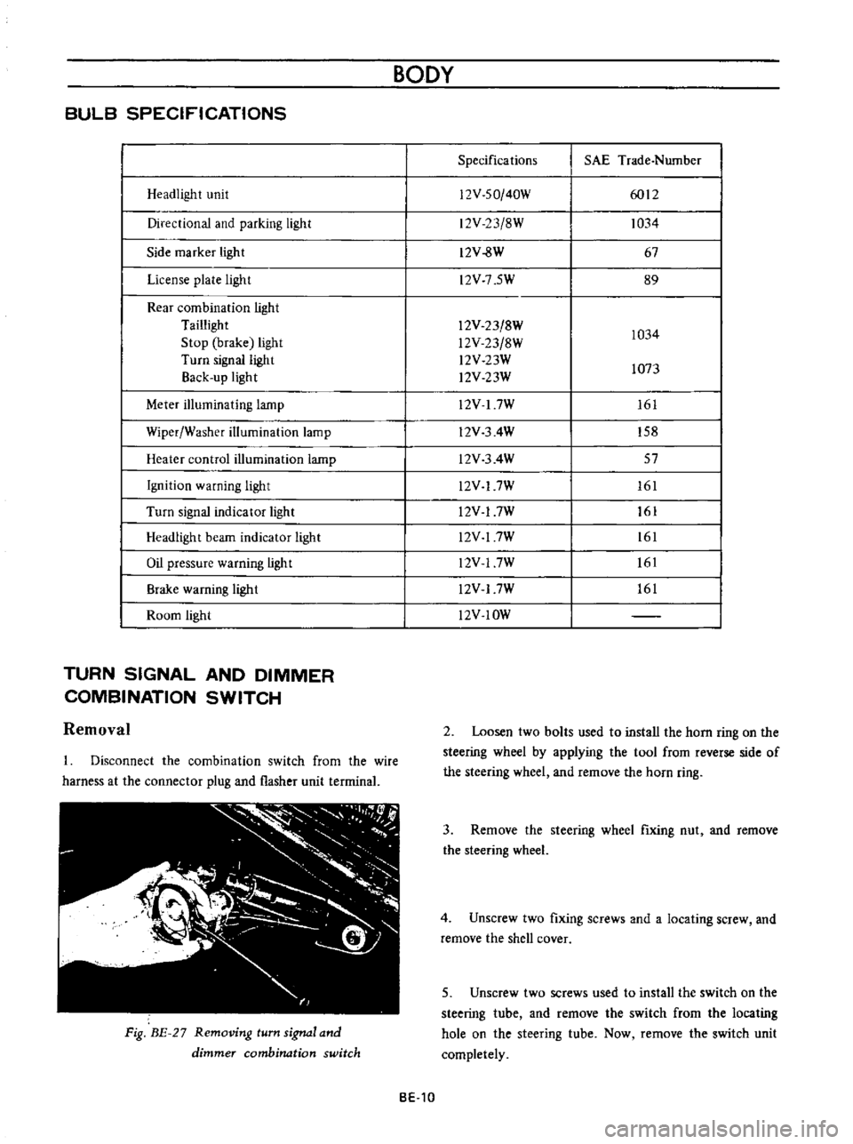
Removal
Disconnect
the
combination
switch
from
the
wire
harness
at
the
connector
plug
and
flasher
unit
terrninal
Fig
BE
27
Removing
turn
signal
and
dimmer
combination
switch
BODY
Specifications
SAE
Trade
Number
12V
SO
40W
6012
12V
23
8W
1034
12V
8W
67
l2V
7
5W
89
12V
23
8W
1034
l2V
23
8W
l2V
23W
1073
l2V
23W
12V
I
7W
161
l2V
3
4W
158
l2V
3
4W
57
l2V
17W
161
l2V
17W
161
l2V
17W
161
l2V
17W
161
l2V
17W
161
l2V
IOW
2
Loosen
two
bolts
used
to
install
the
horn
ring
on
the
steering
wheel
by
applying
the
tool
from
reverse
side
of
the
steering
wheel
and
remove
the
horn
ring
3
Remove
the
steering
wheel
fixing
nut
and
remove
the
steering
wheel
4
Unscrew
two
fixing
screws
and
a
locating
screw
and
remove
the
shell
cover
5
Unscrew
two
screws
used
to
install
the
switch
on
the
steering
tube
and
remove
the
switch
from
the
locating
hole
on
the
steering
tube
Now
remove
the
switch
unit
completely
BE
10
Page 262 of 513

BODY
ELECTRICAL
Wiper
motor
replacement
First
of
all
remove
the
connector
plug
from
the
wiper
motoI
2
Remove
a
nut
used
to
connect
wiper
motor
worm
wheel
shaft
to
the
connecting
rod
from
passenger
compartment
side
dash
panel
3
Loosen
three
bolts
used
to
install
the
wiper
motor
on
the
cowl
dash
remove
the
wiper
motor
4
Reinstall
a
new
wiper
motor
in
reverse
sequence
of
removal
Fig
BE
44
Wiper
motor
Q
V
rt
ir
o
y
At
Jllif
Fig
BE
45
Wiper
motor
linkage
Wiper
blade
operating
range
When
removing
the
wiper
arm
loosen
the
wiper
arm
attaching
nut
and
pull
out
the
wiper
arm
from
the
pivot
shaft
When
installing
the
wiper
arm
on
the
pivot
shaft
provide
the
arm
with
a
proper
installation
angle
so
that
the
windshield
wiper
blade
is
positioned
correctly
The
wiper
arm
attaching
nut
tightening
torque
is
60
5
kg
m
434
36
2lb
ft
Fig
BE
46
Removing
wiper
arm
00
I
i
Fig
BE
47
Wiper
arm
installation
Wiper
washer
switch
replacement
Remove
the
connector
from
back
of
the
wiper
washer
switch
2
Depressing
and
turning
the
wiper
switch
knob
counterclockwise
remove
it
3
Loosen
the
escutcheon
and
remove
the
wiper
switch
from
the
cluster
lid
Washer
nozzle
adjustment
When
the
washer
nozzle
is
installed
or
when
washer
fluid
is
not
sprayed
properly
adjust
the
nozzle
direction
so
that
fluid
is
sprayed
in
range
indicated
in
Figure
BE
48
BE
27
Page 367 of 513
ENGINE
MECHANICAL
3
Apply
engine
oil
to
the
main
bearing
surfaces
on
both
sides
of
the
cylinder
block
and
cap
Install
the
crankshaft
4
Install
the
main
bearing
cap
and
tighten
the
bolts
with
specified
torque
Tightening
torque
5
0
to
6
0
kg
m
36
to
43
ft
lb
Notes
a
Arrange
the
parts
so
that
the
arrow
mark
on
the
bearing
cap
is
faced
toward
the
front
of
the
engine
b
Prior
to
tightening
the
bearing
cap
bolts
place
the
bearing
cap
at
a
proper
position
by
shifting
the
crankshaft
in
the
axial
direction
c
Tighten
the
bearing
cap
bolts
gradually
in
separating
two
to
three
stages
and
outwardly
from
the
center
beari
ng
d
After
securing
the
bearing
cap
bolts
ascertain
that
the
crankshaft
can
be
easily
rotated
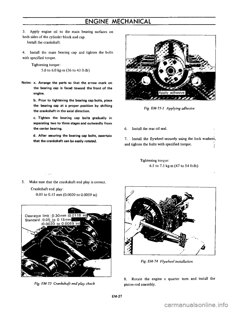
5
Make
sure
that
the
crankshaft
end
play
is
correct
Crankshaft
end
play
0
05
to
0
15
rom
0
0020
to
0
0059
in
Fig
EM
73
Crankshaft
end
play
check
EM
27
Fig
EM
73
t
Applying
adhesive
6
Install
the
rear
oil
seal
7
Install
the
flywheel
securely
using
the
lock
washers
and
tighten
the
bolts
with
specified
torque
Tightening
torque
6
5
to
7
5
kg
m
47
to
54
ft
lb
Iii
Fig
EM
74
Flywheel
installation
8
Rotate
the
engine
a
quarter
turn
and
install
the
piston
rod
assembly