Page 92 of 252
10
9
8
n
o
o
19
1
Water
pump
assembly
11
lock
washer
2
Water
pump
body
12
Hex
bolt
3
Water
pump
ane
13
Hex
bolt
With
lock
washer
4
Water
pump
seal
14
loc
l
washer
17
6
5
Water
pump
beanng
15
Fan
and
water
pump
pulley
6
Water
pump
bee
ring
lock
16
Cooling
tan
7
Water
pump
hub
17
Fan
and
water
pump
lock
8
Water
pump
seat
washer
9
Water
pump
gasket
18
Hex
bolt
10
Hex
bolt
19
Fen
belt
I
I
Page 103 of 252

98
CHAPTER
NINE
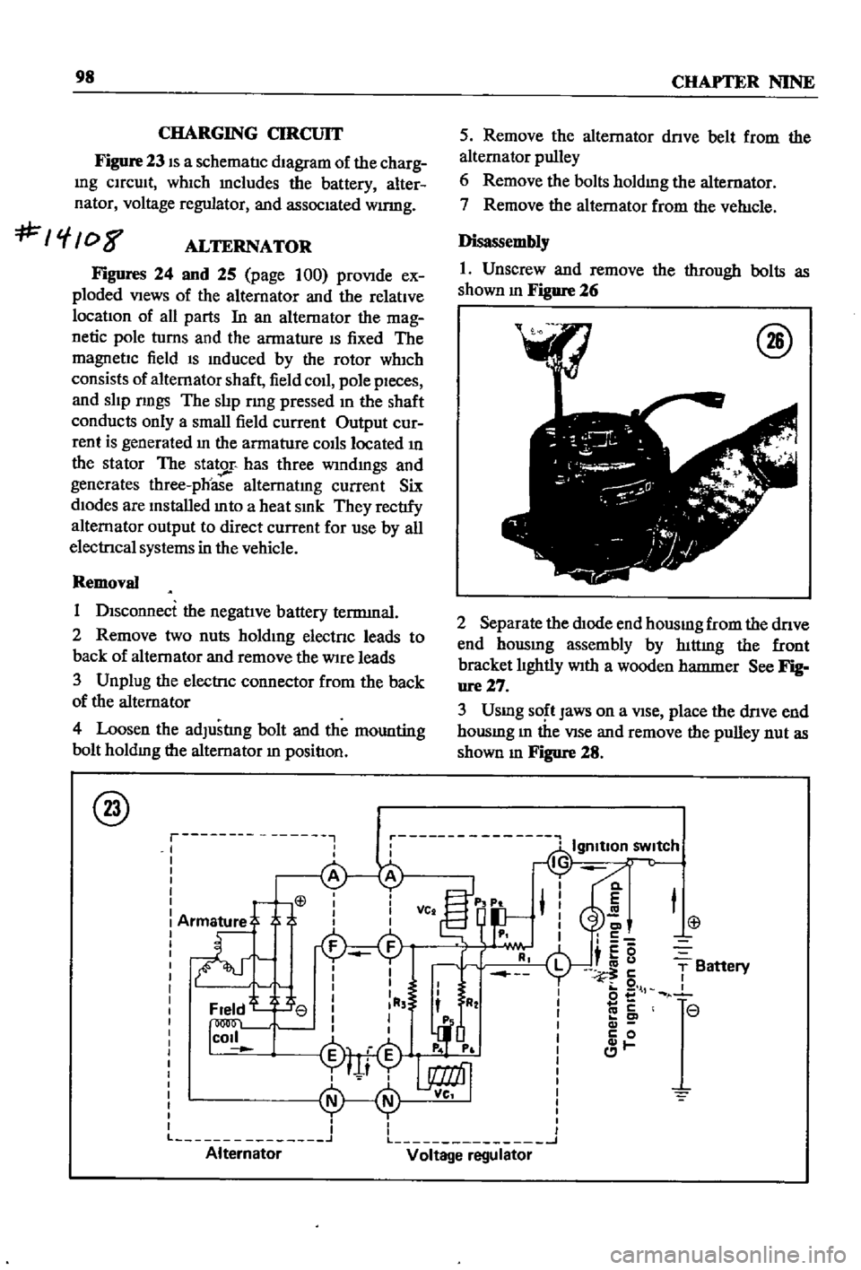
CHARGING
CIRCUIT
Figure
23
IS
a
schematIc
dIagram
of
the
charg
Ing
CIrcuIt
whIch
mcludes
the
battery
alter
nator
voltage
regulator
and
assocIated
wumg
f
08
ALTERNATOR
Figures
24
and
25
page
100
proVIde
ex
ploded
VIews
of
the
alternator
and
the
relatIve
locatIon
of
all
parts
In
an
alternator
the
mag
netic
pole
turns
and
the
armature
IS
fixed
The
magnetIc
field
IS
Induced
by
the
rotor
wh1ch
consists
of
alternator
shaft
field
coIl
pole
pIeces
and
slIp
nngs
The
slIp
rmg
pressed
In
the
shaft
conducts
only
a
small
field
current
Output
cur
rent
is
generated
In
the
armature
COIls
located
In
the
stator
The
stator
has
three
wIndmgs
and
generates
three
phoase
alternatIng
current
Six
dIodes
are
Installed
mto
a
heat
SInk
They
rectIfy
alternator
output
to
direct
current
for
use
by
all
electrIcal
systems
in
the
vehicle
Removal
1
DIsconnect
the
negatIve
battery
terrmnal
2
Remove
two
nuts
holdIng
electnc
leads
to
back
of
alternator
and
remove
the
Wire
leads
3
Unplug
the
electrIc
connector
from
the
back
of
the
alternator
4
Loosen
the
adJustlng
bolt
and
the
mounting
bolt
holdIng
the
alternator
In
positIon
@
r
I
I
I
L
Alternator
5
Remove
the
alternator
dnve
belt
from
the
alternator
pulley
6
Remove
the
bolts
holdmg
the
alternator
7
Remove
the
alternator
from
the
veh1cle
Disassembly
1
Unscrew
and
remove
the
through
bolts
as
shown
m
Figure
26
@
2
Separate
the
dIOde
end
housmg
from
the
dnve
end
hOUSIng
assembly
by
hlttmg
the
front
bracket
lIghtly
WIth
a
wooden
hatnnler
See
Fig
ure27
3
Usmg
SO
t
Jaws
on
a
VIse
place
the
dnve
end
housmg
m
the
VIse
and
remove
the
pulley
nut
as
shown
m
Figure
28
Cl
E
C
c5
i
u
5
o
l
co
c
c
0
1
T
Battery
r
r
L
J
Voltage
regulator
Page 120 of 252
27
10
13
49
j
l
e
1
1
31
33
22
@
@
25
f
1
d
37
36
6
40
ell
o
z
o
o
t
1
Hose
clamp
3
Hose
clamp
4
Connector
pipe
5
Hose
connector
7
Air
pump
With
pulley
8
Air
pump
silencer
assembly
9
Air
pump
pulley
10
Bolt
13
Spring
washer
14
Check
al
e
assembly
15
Anti
backfire
alve
16
Connector
tube
20
Air
gallery
pipe
22
Air
pump
bracket
23
Hex
bolt
25
Spring
washer
27
Adjusting
bar
31
Air
pump
bolt
33
Spring
washer
36
Plain
washer
37
Hex
nut
39
Air
cleaner
to
all
pump
hose
40
All
pump
to
control
al
e
hose
41
Air
pump
to
anti
backfire
val
e
hose
42
Anti
backfire
al
e
hose
44
Hose
clam
p
46
Hose
clam
p
47
Hose
clamp
49
Air
pum
p
belt
50
Rocker
co
er
to
air
cleaner
hose
VI
Page 121 of 252
1
Hose
clemp
3
Hose
clamp
4
Connector
pipe
5
Hose
connector
6
Control
valve
7
Air
pump
with
pulley
9
Air
pump
pulley
11
Bolt
13
Spnng
washer
14
Check
valve
15
Antl
beckllre
elve
17
Connector
tube
19
Hose
c1emp
20
Air
gellery
pipe
22
Air
pum
p
bracket
24
Hex
bolt
26
Spring
washer
27
Adjusting
bar
28
Hex
bolt
29
Spnng
lock
washer
30
Hex
bolt
31
Air
pump
bolt
39
Air
c1eener
to
air
pump
hose
40
Air
pump
to
control
alve
hose
41
Air
pump
to
anti
beckllre
velve
hose
43
Antl
backllre
valve
to
connector
hose
45
Hose
clemp
46
Hose
clemp
48
Hose
c1emp
49
Air
pump
belt
50
Rocker
cover
to
alf
clBllner
hosa
51
Hose
band
54
Velve
1I0w
guide
55
Flow
gulda
valve
brackBt
56
Eveporatlve
control
tube
57
Evaporative
control
tube
58
Eveporatlve
control
tube
59
Hose
clamp
60
Screw
61
Spring
washer
62
Screw
63
Spring
washer
64
Main
breather
tube
50
15
i
Page 127 of 252

122
CHAPTER
TEN
1
Start
the
engIne
and
bnng
It
up
to
normal
operatIng
temperature
2
Inspect
all
hoses
and
connectIons
for
leaks
and
detenoratIon
Shut
off
the
engme
Replace
any
defectIve
hoses
3
Remove
the
hose
attached
to
the
check
valve
4
VIsually
Inspect
the
posItIon
of
the
valve
plate
InsIde
the
valve
body
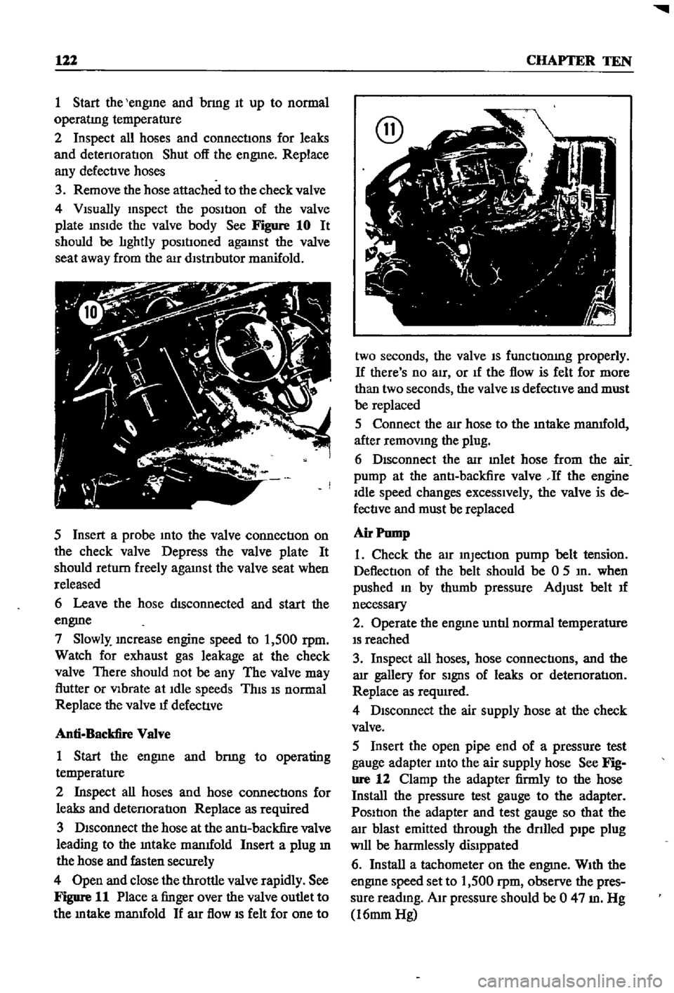
See
Figure
10
It
should
be
lIghtly
posItIoned
agaInst
the
valve
seat
away
from
the
aIr
dlstnbutor
manifold
5
Insert
a
probe
Into
the
valve
connectIon
on
the
check
valve
Depress
the
valve
plate
It
should
return
freely
agaInst
the
valve
seat
when
released
6
Leave
the
hose
dISconnected
and
start
the
engme
7
Slowly
Increase
engine
speed
to
1
500
rpm
Watch
for
exhaust
gas
leakage
at
the
check
valve
There
should
not
be
any
The
valve
may
flutter
or
VIbrate
at
Idle
speeds
ThIS
IS
normal
Replace
the
valve
u
defecuve
Anti
Backfire
Valve
1
Start
the
engme
and
bnng
to
operating
temperature
2
Inspect
all
hoses
and
hose
connectIons
for
leaks
and
detenoratIon
Replace
as
required
3
DIsconnect
the
hose
at
the
antI
backfire
valve
leading
to
the
Intake
manuold
Insert
a
plug
ill
the
hose
and
fasten
securely
4
Open
and
close
the
throttle
valve
rapidly
See
Figure
11
Place
a
finger
over
the
valve
outlet
to
the
m
take
manuold
If
arr
flow
IS
felt
for
one
to
two
seconds
the
valve
IS
functIonIng
properly
If
there
s
no
aIr
or
If
the
flow
is
felt
for
more
than
two
seconds
the
valve
IS
defectIve
and
must
be
replaced
5
Connect
the
alr
hose
to
the
mtake
manuold
after
remOVIng
the
plug
6
DIsconnect
the
aIr
mlet
hose
from
the
air
pump
at
the
antI
backfire
valve
If
the
engine
Idle
speed
changes
excessIvely
the
valve
is
de
fectIve
and
must
be
replaced
Air
Pump
1
Check
the
atr
InjectIon
pump
belt
tension
DeflectIon
of
the
belt
should
be
0
5
In
when
pushed
In
by
thumb
pressure
Adjust
belt
u
necessary
2
Operate
the
engme
untIl
normal
temperature
IS
reached
3
Inspect
all
hoses
hose
connectIons
and
the
arr
gallery
for
SIgnS
of
leaks
or
detenoratIon
Replace
as
required
4
DIsconnect
the
air
supply
hose
at
the
check
valve
5
Insert
the
open
pipe
end
of
a
pressure
test
gauge
adapter
Into
the
air
supply
hose
See
Fig
ure
12
Clamp
the
adapter
firmly
to
the
hose
Install
the
pressure
test
gauge
to
the
adapter
PosItIon
the
adapter
and
test
gauge
so
that
the
alr
blast
emitted
through
the
dnlled
pipe
plug
Will
be
harmlessly
dislppated
6
Install
a
tachometer
on
the
engme
WIth
the
engIne
speed
set
to
1
500
rpm
observe
the
pres
sure
readmg
AIr
pressure
should
be
0
47
m
Hg
16mm
Hg