1900 MITSUBISHI DIAMANTE oil
[x] Cancel search: oilPage 52 of 408
ENGlNEELECTRliAL 2-5
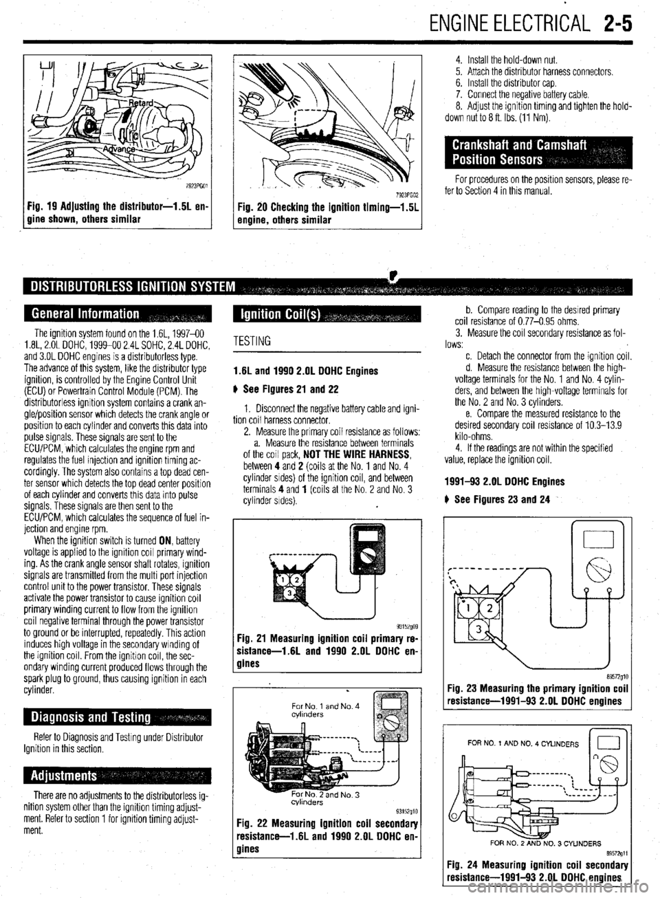
Fig. 19 Adjusting the distributor-1.5L en-
gine shown, others similar
4. Install the hold-down nut.
5. Attach the distributor harness connectors.
6. Install the distributor cap.
7. Connect the negative battery cable.
8. Adjust the ignition timing and tighten the hold-
down nut to 8 ft. Ibs. (11 Nm).
For procedures on the position sensors, please re-
fer to Section 4 in this manual.
The ignition system found on the 1.6L, 1997-60
1.8L, 2.OL DOHC, 1999-00 2.4L SOHC, 2.4L DOHC,
and 3.OL DOHC engines is a distributorless type.
The advance of this system, like the distributor type
ignition, is controlled by the Engine Control Unit
(ECU) or Powertrain Control Module (PCM). The
distributorless ignition system contains a crank an-
gle/position sensor which detects the crank angle or
position to each cylinder and converts this data into
pulse signals. These signals are sent to the
ECLVPCM, which calculates the engine rpm and
regulates the fuel injection and ignition timing ac-
cordingly. The system also contains a top dead cen-
ter sensor which detects the top dead center position
of each cylinder and converts this data into pulse
signals. These signals are then sent to the
ECU/PCM, which calculates the sequence of fuel in-
jection and engine rpm.
When the ignition switch is turned ON, battery
voltage is applied to the ignition coil primary wind-
ing. As the crank angle sensor shaft rotates, ignition
signals are transmitted from the multi port injection
control unit to the power transistor. These signals
activate the power transistor to cause ignition coil
primary winding current to flow from the ignition
coil negative terminal through the power transistor
to ground or be interrupted, repeatedly. This action
induces high voltage in the secondary winding of
the ignition coil. From the ignitron coil, the sec-
ondary winding current produced flows through the
spark plug to ground, thus causing ignition in each
cylinder.
Refer to Diagnosis and Testing under Distributor
Ignition in this section,
There are no adjustments to the distributorless ig-
nition system other than the ignition timing adjust-
ment. Refer to section 1 for ignition timing adjust-
ment.
TESTING
1.6L and 1990 2.OL DOHC Engines
6 See Figures 21 and 22
1. Disconnect the negative battery cable and igni-
tion coil harness connector.
2. Measure the primary coil resistance as follows:
a. Measure the resistance between terminals
of the coil pack,
NOT THE WIRE HARNESS, between 4 and 2 (coils at the No. 1 and No. 4
cylinder srdes) of the ignition coil, and between
terminals 4 and
1 (coils at the No. 2 and No. 3
cylinder sides).
93152go9 Fig. 21 Measuring ignition coil primary re-
sistance-1.6L and 1990 2.OL DDHC en-
gines
.
For No 1 and No. 4
cvlmders
Fig. 22 Measuring ignition coil secondary
resistance-l .6L and 1990 2.OL DOHC en-
gines
b. Compare reading to the desrred primary
coil resistance of 0.77-0.95 ohms.
3. Measure the coil secondary resistance as fol-
lows:
c. Detach the connector from the ignition coil.
d. Measure the resistance between the high-
voltage terminals for the No. 1 and No. 4 cylin-
ders, and between the high-voltage terminals for
the No. 2 and No. 3 cylinders.
e. Compare the measured resistance to the
desired secondary coil resistance of 10.3-13.9
kilo-ohms.
4. If the readings are not within the specified
value, replace the ignition coil.
1991-!I3 2.OL DDHC Engines
# See Figures 23 and 24
n 0
Fig. 23 Measuring the primary ignition coil
resistance-1991-93 2.OL DOHC enoines
I I
FOR NO 1 AND NO. 4 CYLINDERS
Id
FOR NO. 2 AND NO. 3 CYUNDERS
89572611
Fig. 24 Measuring ignition coil secondary
resistance-1991-93 2.OL DOHC engines
Page 53 of 408
2-6 ENGINEELECTRICAL
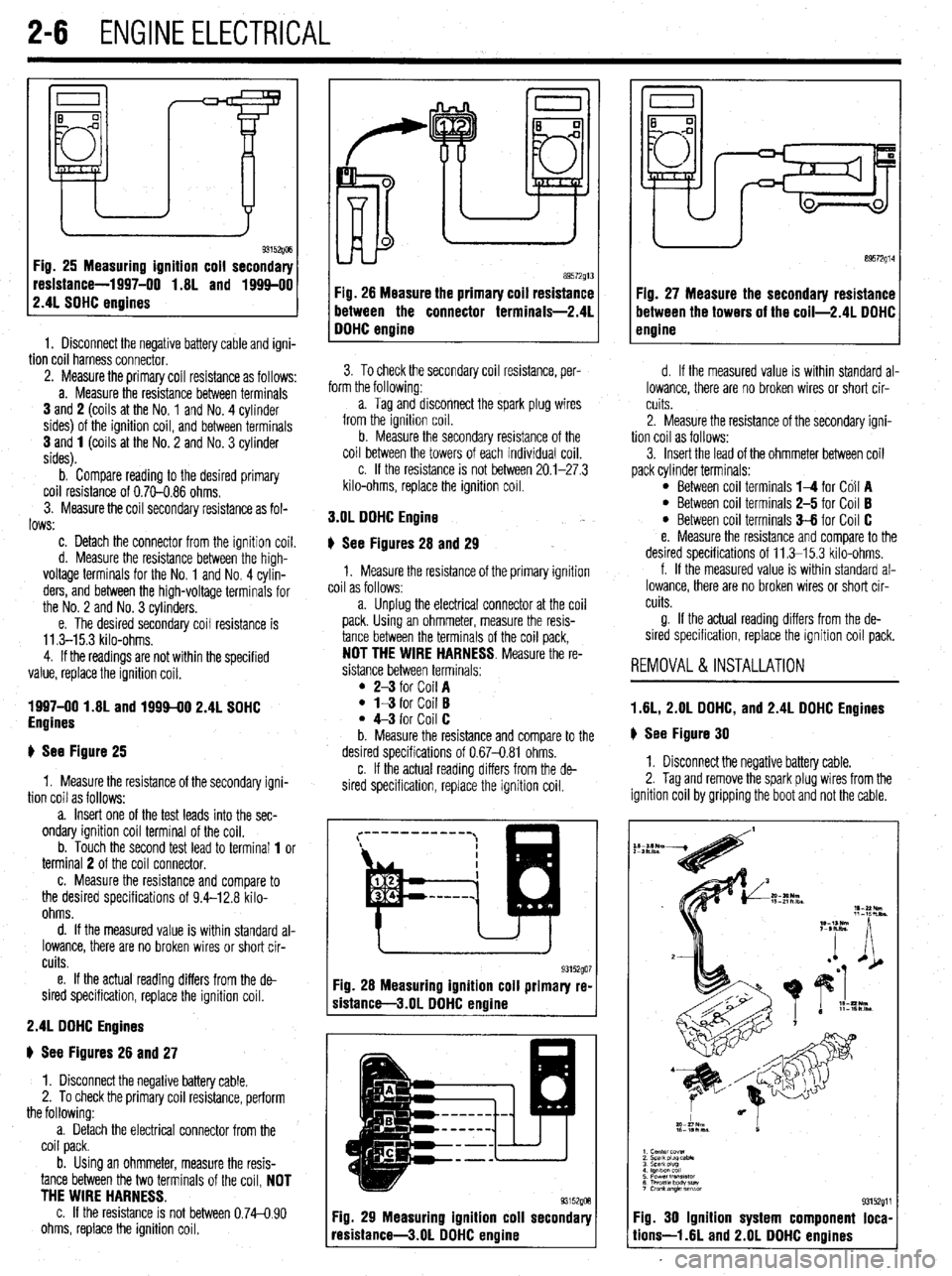
Fig. 26 Measuring ignition coil secondary
resistance-1997-00 1.8L and 1994-00
2.4L SOHC engines
1. Disconnect the negative battery cable and igni-
tion coil harness connector. 89572914
89572g13
Fig. 28 Measure the primary coil resistance Fig. 27 Measure the secondary resistance
between the connector terminals-2.4L between the towers of the coil-2.4L DOHC
DOHC enaine engine
3. To check the secondary coil resistance, per-
. .
term the tollowmg:
a. Tag and disconnect the spark plug wires
from the ignition coil.
b. Measure the secondary resistance of the
coil between the towers of each individual coil.
c. If the resistance is not between 20.1-27.3
kilo-ohms, replace the ignition coil. 2. Measure the primary coil resistance as follows:
a. Measure the resistance between terminals
3 and 2 (coils at the No. 1 and No. 4 cylinder
sides) of the ignition coil, and between terminals
3 and 1 (coils at the No. 2 and No. 3 cylinder
sides).
b. Compare reading to the desired primary
coil resistance of 0.70-0.86 ohms.
3. Measure the coil secondary resistance as fol-
lows: 3.OL DOHC Engine
c. Detach the connector from the ignition coil.
d. Measure the resistance between the high-
voltage terminals for the No. 1 and No. 4 cylin-
ders, and between the high-voltage terminals for
the No. 2 and No. 3 cylinders.
e. The desired secondary coil resistance is
11.3-15.3 kilo-ohms.
4. If the readings are not within the specified
value, replace the ignition coil.
1997-00 1.8L and 1999-00 2.4L SOHC
Engines
+ See Figure 25 6 See Figures 28 and 29
1. Measure the resistance of the primary ignition
coil as follows:
a. Unplug the electrical connector at the coil
pack. Using an ohmmeter, measure the resis-
tance between the terminals of the coil pack,
NOT THE WIRE HARNESS. Measure the re-
sistance between terminals:
l 2-3 for Coil A l l-3 for Coil B l 4-3 for Coil C
b. Measure the resistance and compare to the
desired specifications of 0.67-0.81 ohms.
1. Measure the resistance of the secondarv iani-
tion coil as follows: , -
a. Insert one of the test leads into the sec-
ondary ignition coil terminal of the coil.
b. Touch the second test lead to terminal 1 or
terminal 2 of the coil connector.
c. Measure the resistance and compare to
the desired specifications of 9.4-12.8 kilo-
ohms.
d. If the measured value is within standard al-
lowance, there are no broken wires or short cir-
cuits.
e. If the actual reading differs from the de-
sired specification, replace the ignition coil.
2.4L DDHC Engines
# See Figures 26 and 27
1. Disconnect the negative battery cable.
2. To check the primary coil resistance, perform
the following:
a. Detach the electrical connector from the
coil pack.
b. Using an ohmmeter, measure the resis-
tance between the two terminals of the coil, NOT
THE WIRE HARNESS.
c. If the resistance is not between 0.74-0.90
ohms, replace the ignition coil. c. If the actual reading differs from the de-
sired specification, replace the ignition coil.
Fig. 28 Measuring ignition coil primary re-
sistance-3.01 DOHC engine
Fig. 29 Measuring ignition coil secondary
resistance-3.01 DOHC enaine d. If the measured value is within standard al-
lowance, there are no broken wires or short cir-
cuits.
2. Measure the resistance of the secondary igni-
tion coil as follows:
3. Insert the lead of the ohmmeter between coil
pack cylinder terminals:
l Between coil terminals l-4 for Co11 A l Between coil terminals 2-5 for Coil B l Between coil terminals 3-6 for Coil C
e. Measure the resistance and compare to the
desired specifications of 11.3-l 5.3 kilo-ohms.
f. If the measured value is within standard al-
lowance, there are no broken wires or short cir-
cuits.
g. If the actual reading differs from the de-
sired specification, replace the ignition coil pack.
REMOVAL&INSTALLATION
1.6L, 2.OL DOHC, and 2.4L DOHC Engines
# See Figure 30
1. Disconnect the negative battery cable.
2. Tag and remove the spark plug wires from the
ignition coil by gripping the boot and not the cable.
I
~::::L “1
I cemer Cwer
2 Scabpiwcabk
3 SPaark piug
I lgnlllancoll
5 Powertran3lrtor
6 ThrotflsDcnv*w
I Crankangle lmsm
93152g11
Fig. 30 Ignition system component loca-
lions-l .6L and 2.OL DOHC engines
Page 54 of 408
ENGINEELECTRICAL 2-7
3. Detach the electrical connectors for the COIL
4. Remove the retaining screws and coil from en-
gine.
5. Installation is the reverse of the removal proce-
dure.
1997-00 1.81 and 1994-00 2.4L Engines
) See Figure 31
1, Disconnect the negative battery cable.
2. Detach the electrical connector(s) for the
coil(s).
3. Remove the spark plug wire(s) to the compan-
ion cylinder(s).
4 Remove the coil retaining bolts and lift the coil
from the cylinder head.
5. The installation is the reverse of the removal.
3.OL DOHC Engine
# See Figure 32
1, Disconnect the negative battery cable.
2. Remove the intake manifold plenum (upper in-
take mamfold) Refer to Section 3.
3. Tag and remove the spark plug wires from the
ignition coil by gripping the boot and not the cable.
4 Detach the electrical connectors for the coil.
5. Remove the retaining screws and coil from en-
gine.
6. Installation is the reverse of the removal proce-
dure.
REMOVAL &INSTALLATION
1 AL, 2.01 DOHC, and 2.4L DOHC Engines
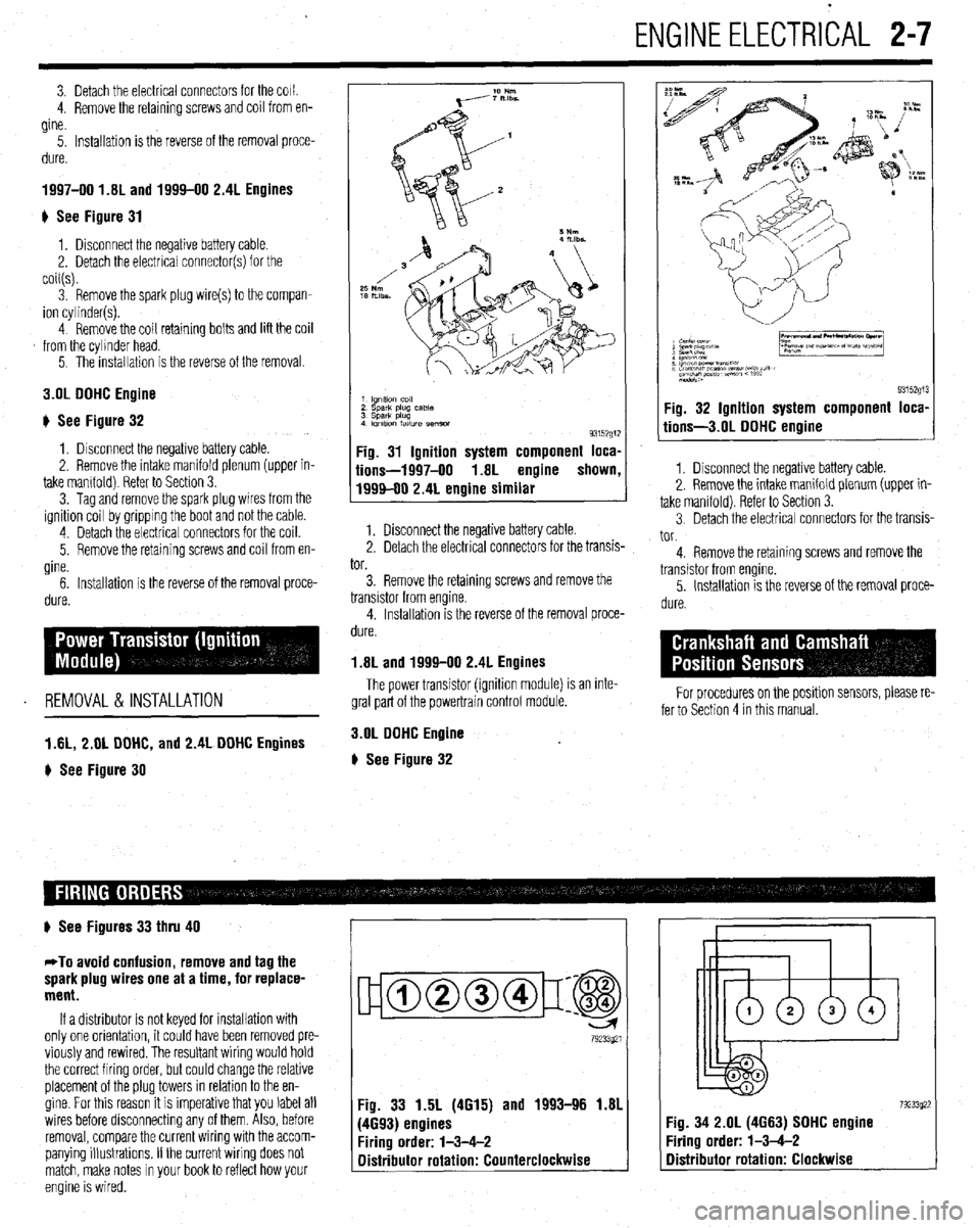
) See Figure 30
1 lgnltlo” co,,
2 sparlt plug case
3 Spark plug
4 Imltlon fatlure semm
93152g1:
Fig. 31 Ignition system component loca,
iions-1997-00 1.8L engine shown
1999-00 2.4L engine similar
1. Disconnect the negative battery cable.
2. Detach the electrical connectors for the transis-
tor.
3. Remove the retaining screws and remove the
transistor from engine.
4. Installation is the reverse of the removal proce-
dure.
1.8L and 1999-00 2.4L Engines
The power transistor (ignition module) is an inte-
gral part of the powertrain control module.
3.OL DOHC Engine
# See Figure 32
9315291 Fig. 32 Ignition system component loca,
tions-3.01 DOHC engine
1. Disconnect the negative battery cable.
2. Remove the intake manifold plenum (upper in-
take manifold). Refer to Section 3.
3 Detach the electrical connectors for the transis-
tor.
4. Remove the retaining screws and remove the
transistor from engine.
5. Installation is the reverse of the removal proce-
dure.
For procedures on the positlon sensors, please re-
fer to Section 4 in this manual.
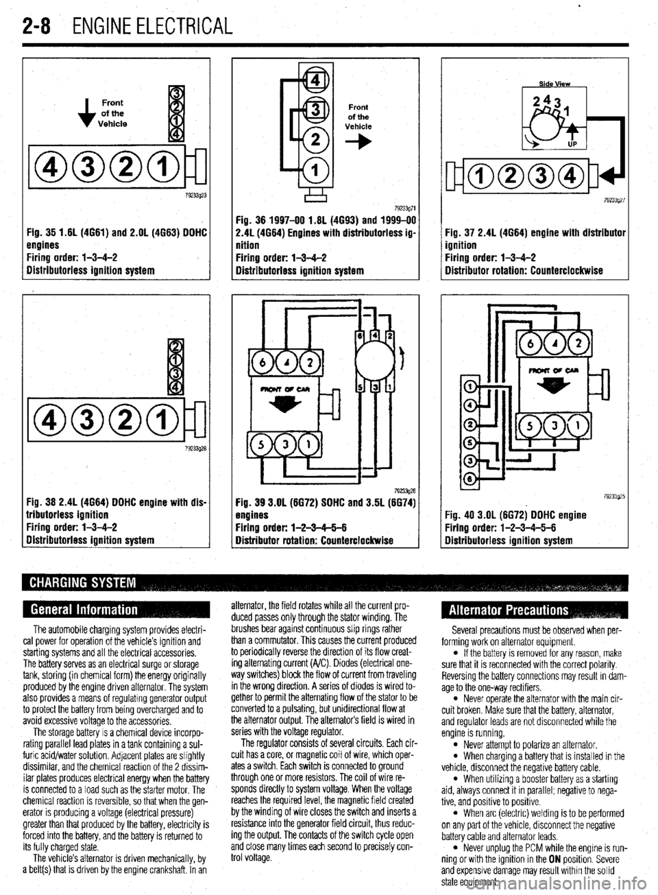
# See Figures 33 thru 40
*To avoid confusion, remove and tag the
spark plug wires one at a time, for replace-
ment.
If a distributor is not keyed for installation with
only one orientation, it could have been removed pre-
viously and rewired. The resultant wiring would hold
the correct firing order, but could change the relative
placement of the plug towers in relation to the en-
gine. For this reason it is imperative that you label all
wires before disconnecting any of them. Also, before
removal, compare the current wiring with the accom-
panying illustrations. If the current wiring does not
match, make notes in your book to reflect how your
engine is wired.
ujamm-p:@
79233921
Fig. 33 1.5L (4615) and 1993-96 1.81
(4693) engines
Firing order: l-3-4-2
Distributor rotation: Counterclockwise 7923392: :ig. 34 2.OL (4663) SOHC engine
‘iring order: l-3-4-2
Distributor rotation: Clockwise
Page 55 of 408
.
2-8 ENGINEELECTRICAL
Front
of the
Vehicle
Fig. 35 1.61(4661) and 2.OL (4663) DDHC
engines
Firing order: l-3-4-2
Distributorless ignition system
Fig. 36 2.4L (4664) DDHC engine with dis-
lributorless ignition
Firing order: l-3-4-2
gistributorless ignition system
Front
of the
Vehicle
+
Fig. 36 1997-00 1.6L (4693) and 1999-00
2.41(4664) Engines with distributorless ig-
nition
Firing order: l-3-4-2
Distributorless ignition system
792!33g26 Fig. 39 3.OL (6672) SDHC and 3.5L (6674)
engines
Firing order: l-2-3-65-6
Distributor rotation: Counterclockwise Fig. 37 2.4L (4664) engine with distributor
ignition
Firing order: l-3-4-2
Distributor rotation: Counterclockwise
:ig. 40 3.OL (6672) DDHC engine
Yring order: l-2-3-4-5-6
Iistributorless ignition system
The automobile charging system provides electri-
cal power for operation of the vehicle’s ignition and
starting systems and all the electrical accessories.
The battery serves as an electrical surge or storage
tank, storing (in chemical form) the energy originally
produced by the engine driven alternator. The system
also provides a means of regulating generator output
to protect the battery from being overcharged and to
avoid excessive voltage to the accessories.
The storage battery IS a chemical device incorpo-
rating parallel lead plates in a tank containing a sul-
furic acid/water solution. Adjacent plates are slightly
dissimilar, and the chemical reaction of the 2 dissim-
ilar plates produces electrical energy when the battery
is connected to a load such as the starter motor. The
chemical reaction is reversible, so that when the gen-
erator IS producing a voltage (electrical pressure)
greater than that produced by the battery, electricity is
forced into the battery, and the battery is returned to
its fully charged state.
The vehicle’s alternator is driven mechanically, by
a belt(s) that is driven by the engine crankshaft. In an alternator, the field rotates while all the current pro-
duced passes only through the stator winding. The
brushes bear against continuous slip rings rather
than a commutator. This causes the current produced
to periodically reverse the direction of its flow creat-
ing alternating current (A/C). Diodes (electrical one-
way switches) block the flow of current from traveling
in the wrong direction. A series of diodes is wired to-
gether to permit the alternating flow of the stator to be
converted to a pulsating, but unidirectional flow at
the alternator output, The alternators field is wired in
series with the voltage regulator.
The regulator consists of several circuits. Each cir-
cuit has a core, or magnetic coil of wire, which oper-
ates a switch. Each switch is connected to ground
through one or more resistors. The coil of wire re-
sponds directly to system voltage. When the voltage
reaches the required level, the magnetic field created
by the winding of wire closes the switch and inserts a
resistance into the generator field circuit, thus reduc-
ing the output. The contacts of the switch cycle open
and close many times each second to precisely con-
trol voltage. Several precautions must be observed when per-
forming work on alternator equipment.
l If the battery is removed for any reason, make
sure that it is reconnected with the correct polarity.
Reversing the battery connections may result In dam-
age to the one-way rectifiers.
l Never operate the alternator with the main cir-
cuit broken. Make sure that the battery, alternator,
and regulator leads are not disconnected while the
engine is running.
l Never attempt to polarize an alternator. l When charging a battery that is installed in the
vehicle, disconnect the negative battery cable.
l When utilizing a booster battery as a starting
aid, always connect it in parallel; negatrve to nega-
tive, and positive to positrve.
l When arc (electric) welding is to be performed
on any part of the vehicle, disconnect the negative
battery cable and alternator leads.
l Never unplug the PCM while the engine is run-
ning or with the ignition in the ON position. Severe
and expensive damage may result within the solid
state equipment.
Page 58 of 408
ENGINE ELECTRICAL 2-11
l.unVeMlil(GSflWtWJ
2.Gwwator harness con- connectk,,,
3. Engme OS, level d,pst,&
4 Generator
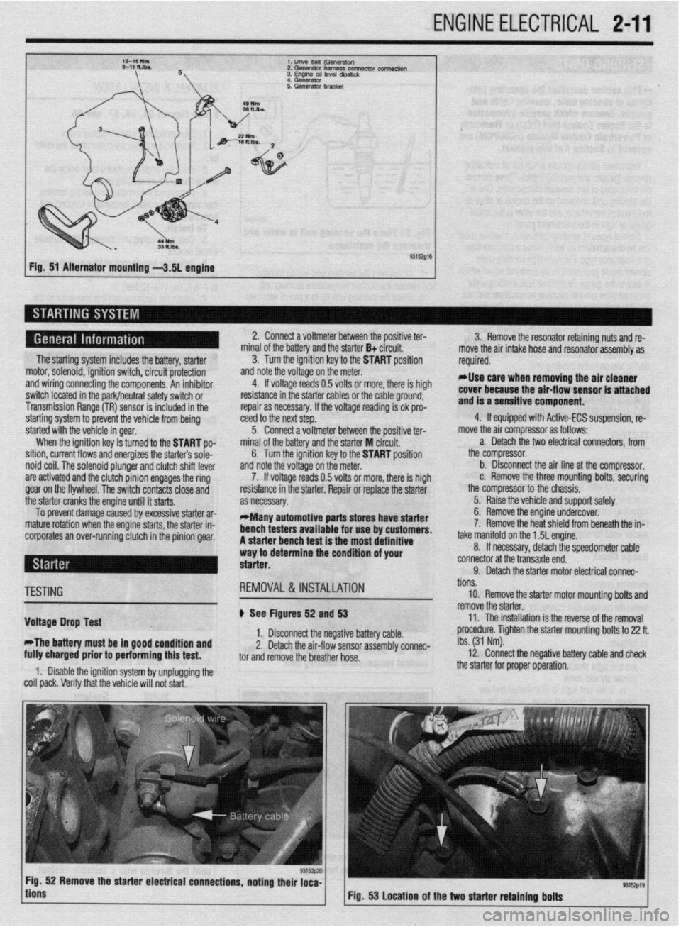
Fig. 51 Alternator mounting -3.51 engine
The starting system includes the battery, starter
motor, solenoid, ignition switch, circuit protection
and wiring connecting the components. An inhibitor
switch located in the park/neutral safety switch or
Transmission Range (TR) sensor is included in the
starting system to prevent the vehicle from being
started with the vehicle in gear.
When the ignition key is turned to the START po-
sition, current flows and energizes the starters sole-
noid coil. The solenoid plunger and clutch shift lever
are activated and the clutch pinion engages the ring
gear on the flywheel. The switch contacts close and
the starter cranks the engine until it starts.
To prevent damage caused by excessive starter ar-
mature rotation when the engine starts, the starter in-
corporates an over-running clutch in the pinion gear. 2. Connect a voltmeter between the positive ter-
minal of the battery and the starter B+ circuit.
3. Turn the ignition key to the START position
and note the voltage on the meter.
4. If voltage reads 0.5 volts or more, there is high
resistance in the starter cables or the cable ground,
repair as necessary. If the voltage reading is ok pro-
teed to the next step.
5. Connect a voltmeter between the positive ter-
minal of the battery and the starter M circuit,
6. Turn the ignition key to the START position
and note the voltage on the meter.
7. If voltage reads 0.5 volts or more, there is high
resistance in the starter. Repair or replace the starter
as necessary.
*Many automotive parts stores have starter
bench testers available for use by customers.
A starter bench test is the most definitive
way to determine the condition of your
starter. 3. Remove the resonator retaining nuts and re-
move the air intake hose and resonator assembly as
required.
rllse care when removing the air cleaner
cover because the air-flow sensor is attached
and is a sensitive component.
4. If equipped with Active-ECS suspension, re-
move the air compressor as follows:
a. Detach the two electrical connectors, from
the compressor.
b. Disconnect the air line at the compressor.
c. Remove the three mounting bolts, securing
the compressor to the chassis.
5. Raise the vehicle and support safely.
6. Remove the engine undercover.
7. Remove the heat shield from beneath the in-
take manifold on the 1.5L engine.
8. If necessary, detach the speedometer cable
connector at the transaxle end.
9. Detach the starter motor electrical connac-
TESTING
Voltage Drop Test
*The battery must be in good condition and
fully charged prior to performing this test. REMOVAL&INSTALLATION
# See Figures 52 and 53
1. Disconnect the negative battery cable.
2. Detach the air-flow sensor assembly connec-
tor and remove the breather hose.
1. Disable the ignition system by unplugging the
coil pack. Verify that the vehicle will not start. tions.
10. Remove the starter motor mounting bolts and
remove the starter.
11. The installation is the reverse of the removal
procedure. Tighten the starter mounting bolts to 22 ft.
Ibs. (31 Nm).
12. Connect the negative battery cable and check
the starter for proper operation.
9315zp19 Fig. 53 Location of the two starter retaining bolts
Page 60 of 408
ENGINE ELECTRlCiL 2-13
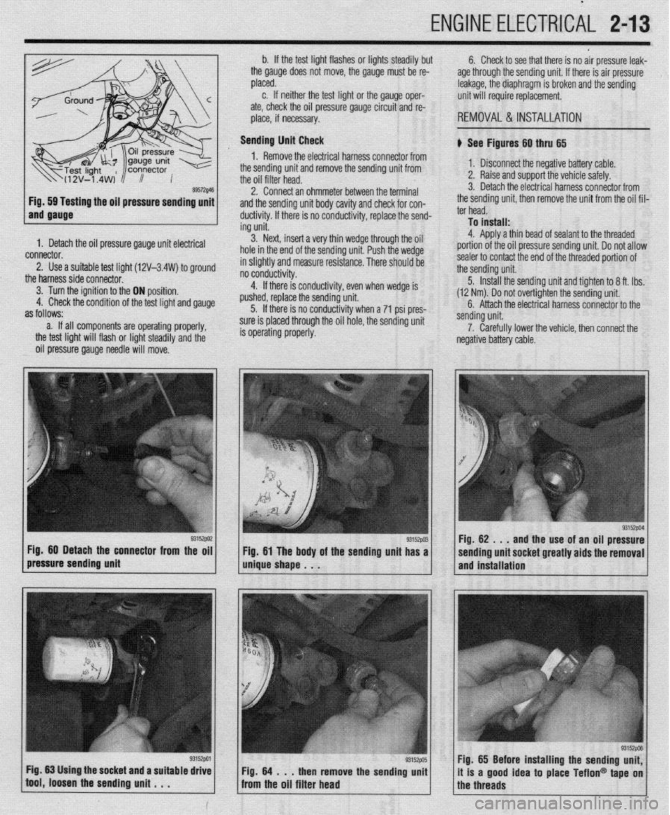
ing the oil pressure sending unit
1. Detach the oil pressure gauge unit electrical
connector.
2. Use a suitable test lioht (12V-3.4W) to around
the harnesssideconnecto~ ’ ’ -
3. Turn the ignition to the ON position.
4. Check the condition of the test light and gauge
as follows:
a. If all components are operating properly,
the test light will flash or light steadily and the
oil pressure gauge needle will move. b. If the test light flashes or lights steadily but
the gauge does not move, the gauge must be re-
placed.
c. If neither the test light or the gauge oper-
ate, check the oil pressure gauge circuit and re-
place, if necessary.
Sending Unit Check
1. Remove the electrical harness connector from
the sending unit and remove the sending unit from
the oil filter head.
2. Connect an ohmmeter between the terminal
and the sending unit body cavity and check for con-
ductivity. If there is no conductivity, replace the send-
ing unit.
3. Next, insert a very thin wedge through the oil
hole in the end of the sending unit. Push the wedge
in slightly and measure resistance. There should be
- - -- d . . . .
no conoucovey.
4. If there is conductivity, even when wedge is
pushed, replace the sending unit.
5. If there is no conductivity when a 71 psi pres-
sure is placed through the oil hole, the sending unit
is operating properly. 6. Check to see that there is no air pressure leak-
age through the sending unit. If there is air pressure
leakage, the diaphragm is broken and the sending
unit will require replacement.
REMOVAL &INSTALLATION
b See Figures 60 thru 65
1. Disconnect the negative battery cable.
2. Raise and support the vehicle safely.
3. Detach the electrical harness connector from
the sending unit, then remove the unit from the oil fil-
ter head.
To install:
4. Aoolv a thin bead of sealant to the threaded
portion of the oil pressure sending unit. Do not allow
sealer to contact the end of the threaded portion of
the sending unit.
5. Install the sending unit and tighten to 8 ft. tbs.
(12 Nm). Do not over-tighten the sending unit.
6. Attach the electrical harness connector to the
/pressure sending unit g3’9wi / m&e shape . . . Fig 60 Detach the connector from the oil
g3152w Fig 61 The body of the sending unit has a sending unit.
7. Carefully lower the vehicle, then connect the
negative battery cable.
93152PM Fig. 62 . , .
and the use of an oil pressure
sending unit socket greatly aids the removal
and installation
Fig. 65 Before installing the sending unit,
it is a good idea to place Teflon@ tape on
the threads
Page 62 of 408
ENGINE MECHANICAL 3-1
ENGINE 3-1
REMOVAL &INSTALLATION 3-l
ROCKERARM(VALVE)COVER 3-l
REMOVAL &INSTALLATION 3-l
ROCKER ARM/SHAFTS 3-4
REMOVAL & INSTALLATION 3-4
THERMOSTAT 3-7
REMOVAL & INSTALLATION 3-7
INTAKE MANIFOLD 3-7
REMOVAL & INSTALLATION 3-7
EXHAUSTMANIFOLD 3-14
REMOVAL &INSTALLATION 3-14
TURBOCHARGER 3-17
REMOVAL & INSTALLATION 3-17
RADIATOR 3-18
REMOVAL & INSTALLATION 3-18
ENGINE FAN 3-19
REMOVAL &INSTALLATION 3-19
WATER PUMP 3-20
REMOVAL & INSTALLATION 3-20
CYLINDER HEAD 3-23
REMOVAL &INSTALLATION 3-23
OIL PAN 3-30
REMOVAL & INSTALLATION 3-30
OIL PUMP 3-33
REMOVAL &INSTALLATION 3-33
CRANKSHAFT DAMPER 3-36
REMOVAL &INSTALLATION 3-36
TIMING COVERAND BELT 3-36
REMOVAL & INSTALLATION 3-36
INSPECTION 3-48
FRONT CRANKSHAFTSEAL 3-48
REMOVAL & INSTALLATION 3-48
CAMSHAFT,BEARlNGSAND
LIFTERS 3-48
REMOVAL & INSTALLATION 3-48
INSPECTION 3-53
BALANCE SHAFT 3-54
REMOVAL &INSTALLATION 3-54
REAR MAIN SEAL 3-54
REMOVAL&INSTALLATION 3-54
FLYWHEEL/DRIVEPLATE 3-55
REMOVAL &INSTALLATION 3-55
EXHAUST SYSTEM 3-55
INSPECTION 3-55
REPLACEMENT 3-56
ENGINE RECONDITIONING 3-57
DETERMINIG ENGINE CONDITION 3-57
COMPRESSION TEST 3-57
OIL PRESSURETEST 3-57
BUYOR REBUILD? 3-57
ENGINE OVERHAULTIPS 3-58
TOOLS 3-58
OVERHAULTIPS 3-58
CLEANING 3-58
REPAIRING DAMAGEDTHREADS 3-59
ENGINE PREPARATION 3-59
CYLINDER HEAD 3-60
DISASSEMBLY 3-60
INSPECTION 3-
REFINISHING & REPAIRING 3-63 ASSEMBLY 3-64
ENGINE BLOCK 3-65
GENERALINFORMAITON 3-65
DISASSEMBLY 3-65
INSPECTION 3-65
REFINISHING 3-67
ASSEMBLY 3-67
ENGINE START-UP AND BREAK-IN 3-
STARTING THE ENGINE 3-69
BREAKING IT IN 3-69
KEEP IT MAINTAINED 3-69
SPECIFICATIONS CHARTS
ENGINE MECHANICAL
SPECIFICATIONS 3-70
TORQUE SPECIFICATIONS 3-81 .69
Page 63 of 408
3-2 ENGINEANDENGINEOVERHAUL
REMOVAL &INSTALLATION
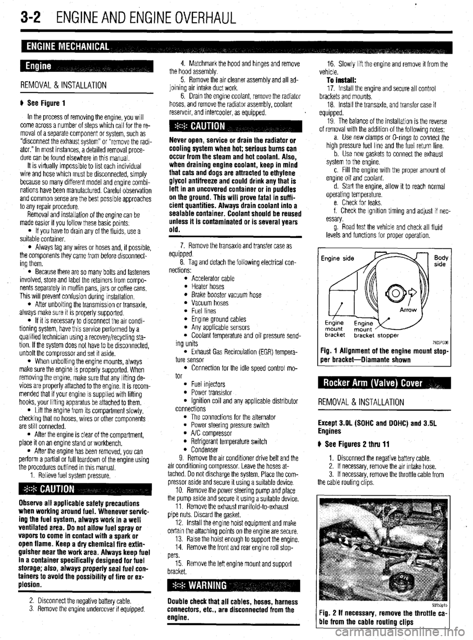
# See Figure 1
In the process of removing the engine, you will
come across a number of steps which call for the re-
moval of a separate component or system, such as
“disconnect the exhaust system” or “remove the radi-
ator.” In most instances, a detailed removal proce-
dure can be found elsewhere in this manual.
It is virtually impossible to list each individual
wire and hose which must be disconnected, simply
because so many different model and engrne combi-
nations have been manufactured Careful observation
and common sense are the best possible approaches
to any repair procedure.
Removal and installation of the engine can be
made easier if you follow these basic points:
l If you have to drain any of the fluids, use a
suitable container.
l Always tag any wires or hoses and, if possrble,
the components they came from before disconnect-
ing them.
l Because there are so many bolts and fasteners
involved, store and label the retainers from compo-
nents separately in muffin pans, jars or coffee cans.
This will prevent confusion during installatron.
l After unbolting the transmisston or transaxle,
always make sure it is properly supported.
l If it is necessary to disconnect the air condi-
tioning system, have this service performed by a
qualified technician using a recovery/recycling sta-
tion If the system does not have to be disconnected,
unbolt the compressor and set it aside.
l When unbolting the engine mounts, always
make sure the engine is properly supported. When
removing the engine, make sure that any lifting de-
vices are properly attached to the engine. It is recom-
mended that if your engine IS supplied with lifting
hooks, your lifting apparatus be attached to them.
l Lift the engine from its compartment slowly,
checking that no hoses, wires or other components
are still connected.
l After the engine is clear of the compartment,
place it on an engine stand or workbench.
l After the engine has been removed, you can
perform a partial or full teardown of the engine using
the procedures outlined in this manual.
1. Relieve fuel system pressure.
Observe all applicable safety precautions
when working around fuel. Whenever servic-
ing the fuel system, always work in a well
ventilated area. Do not allow fuel spray or
vapors to come in contact with a spark or
open flame. Keep a dry chemical fire extin-
guisher near the work area. Always keep fuel
in a container specifically designed for fuel
storage; also, always properly seal fuel con-
tainers to avoid the possibility of fire or ex-
plosion.
2. Disconnect the negative battery cable.
3. Remove the engine undercover if equipped. 4. Matchmark the hood and hinges and remove
the hood assembly.
5. Remove the air cleaner assembly and all ad-
joining air intake duct work.
6. Drain the engine coolant, remove the radiator
hoses, and remove the radiator assembly, coolant
reservoir, and intercooler, as equipped.
cooling system when hot; serious burns can
occur from the steam and hot coolant. Also,
when draining engine coolant, keep in mind
that cats and dogs are attracted to ethylene
glycol antifreeze and could drink any that is
left in an uncovered container or in puddles
on the ground. This will prove fatal in suffi-
cient quantities. Always drain coolant into a
sealable container. Coolant should be reused
unless it is contaminated or is several years
old.
7. Remove the transaxle and transfer case as
equipped.
8. Tag and detach the following electrical con-
nections:
l Accelerator cable l Heater hoses l Brake booster vacuum hose l Vacuum hoses l Fuel lines l Engine ground cables l Any applicable sensors l Coolant temperature and oil pressure send-
ing units
l Exhaust Gas Recirculation (EGR) tempera-
ture sensor
l Connection for the idle speed control mo-
tor
l Fuel injectors l Power transistor l Ignition coil and any applicable distributor
connections
l The connections for the alternator l Power steering pressure switch l A/C compressor l Refrigerant temperature switch l Condenser
9. Remove the air conditioner drive belt and the
air conditioning compressor. Leave the hoses at-
tached. Do not discharge the system. Place the com-
pressor aside and secure it using a suitable device.
10. Remove the power steering pump and place
the pump asrde and secure it using a surtable device.
11. Remove the exhaust manifold-to-exhaust
pipe nuts. Discard the gasket.
12. Install the engine hoist equipment and make
certain the attaching points on the engine are secure.
13. Raise the hoist enough to support the engine.
14. Remove the front and rear engine roll stop-
pers
15. Remove the left engine mount and support
Double check that all cables, hoses, harness
connectors, etc., are disconnected from the
engine.
16. Slowly lift the engine and remove it from the
vehicle.
To install:
17. Install the engine and secure all control
brackets and mounts.
18. Install the transaxle, and transfer case if
equipped.
19. The balance of the installation is the reverse
of removal with the addition of the following notes:
a. Use new clamps or O-rings to connect the
high pressure fuel lme and the fuel return line.
b. Use new gaskets to connect the exhaust
system to the engine.
c. Fill the engine with the proper amount of
engine oil and coolant.
d. Start the engine, allow it to reach normal
operating temperature.
e. Check for leaks.
f. Check the ignition timing and adjust if nec-
essary.
g. Road test the vehicle and check all fluid
levels and functions for proper operation.
Fig. 1 Alignment of the engine mount stop-
oer bracket-Diamante shown
REMOVAL &INSTALLATION
Except 3.OL (SOHC and DOHC) and 3.5L
Engines
# See Figures 2 thru 11
1. Disconnect the negative battery cable.
2. If necessary, remove the air intake hose.
3. If necessary, remove the throttle cable from
the cable routing clips.
Fig. 2 If necessary, remove the throttle ca-
ble from the cable routing clips