1900 MITSUBISHI DIAMANTE wheel bolt torque
[x] Cancel search: wheel bolt torquePage 310 of 408
SUSPENSION AND STEERING 845
144-188 ft. Ibs. (200-260 Nm). Rotate the hub ing knuckle and install a new nut. Tighten to 52 ft. 3. Remove the cotter pin, halfshaft nut and
to seat the bearing.
Ibs. (72 Nm). washer.
e. Mount the knuckle assembly in a vise.
12. Install the halfshaft into the hub/knuckle as- 4. If equipped with ABS, remove the Vehicle
Check the hub assembly turning torque and end- sembly.
Speed Sensor (VSS).
play as follows: 13. Install the two front strut lower mounting bolts
5. Remove the caliper and brake pads. Support
l Using a torque wrench and socket
and tighten to 80-94 ft. Ibs. (110-130 Nm) on Mirage
the caliper out of the way using wire.
MB990998 or equivalent, turn the hub in the or 65-76 ft. Ibs. (90-105 Nm) on Diamante models. 6. Remove the brake rotor from the hub assembly.
knuckle assembly. Note the reading on the torque
14. Install the tie rod end and tighten the nut to 7. Disconnect the upper ball joint from the
wrench and compare to the desired reading of 16
25 ft. lbs. (34 Nm) for Mirage and 21 ft. Ibs. (29 Nm) steering knuckle and pull the knuckle outward.
inch Ibs. (1.8 Nm) or less. This is known as the ‘on Diamante models
8. From the back of the knuckle, remove the
breakaway torque.
15. Install the brake disc and caliper assembly. ‘four bolts securing the hub to the knuckle.
l Check for roughness when turning the
16. If equipped with Active-ECS, connect the
9. Remove the hub and bearing assembly from
bearing.
height sensor and tighten the mounting bolt to 15 ft.
the knuckle.
0 Mount a dial indicator on the hub so the
Ibs. (20 Nm).
pointer contacts the machined surface on the hub.
17. Install the front speed sensor, if removed.
*The hub assembly is not serviceable and
l Check the end-play.
18. Install the washer and new locknut to the end should not be disassembled.
l Compare the reading to the limit of 0.002
in. (0.05mm). of the halfshaft. Tighten the locknut snugly to To install: 144-188 ft. Ibs. (200-260 Nm).
f. If the starting torque or the hub end-play
19. Install the tire and wheel assembly onto the 10. Install the hub to the steering knuckle and
are not within specifications while the nut is tighten the mounting bolts to 65 ft. Ibs. (88 Nm).
vehicle.
11.
tightened to 144-188 ft. Ibs. (200-260 Nm), the
Lower the vehicle to the ground. Connect the upper ball joint to the steering
20.
bearing, hub or knuckle have probably not been ‘knuckle and tighten the self-locking nut to 21 ft. Ibs.
(28 Nm).
installed correctly. Repeat the disassembly and 1994-98 Galant 12.
‘assembly procedure and recheck starting torque Install the axle washer and nut. Tighten the
and end-play. nut to 145-188 ft. Ibs. (200-260 Nm).
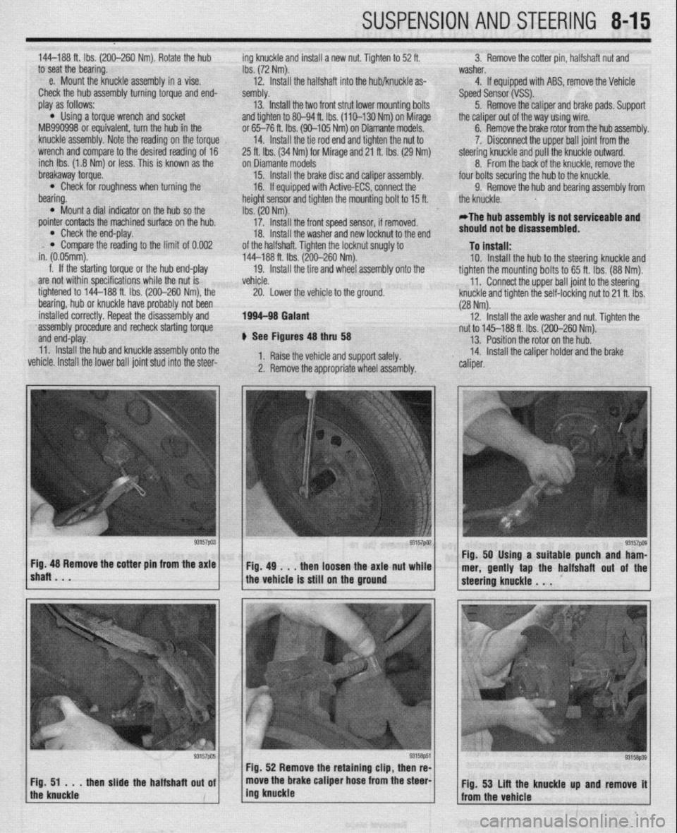
+ See Figures 48 thru 58 13. Position the rotor on the hub.
11. Install the hub and knuckle assembly onto the
vehicle. Install the lower ball joint stud into the steer- 1. Raise the vehicle and support safely. 14. Install the caliper holder and the brake
2. Remove the appropriate wheel assembly. ” caliper.
lshaRBmV * “57pa3~ ~Fig.4g~..thenloosehtheaxlattut~~;.~ Fig. 48 Remove the cotter pm from the axle Fig. 50 Using a suitable punch and ham-
mer, gently tap the halfshaft out of the
the vehicle is still on the ground
Page 322 of 408
8-26 SUSPENSION AND STEERING
torqued to specifications. The wheel bearings are
sealed units and are not adjustable. If defective, re-
placement is the only option.
REMOVAL &INSTALLATION
Mirage
7996-92 MODELS
1. Raise the vehicle and support safely.
2. Remove the tire and wheel assembly.
3. If equipped with rear disc brakes, remove the
caliper from the disc and remove the brake disc.
4. Remove the dust cap and bearing nut. Do not
use an air gun to remove the nut.
5. Remove the outer wheel bearing.
6. Remove the drum and/or axle hub with the
inner wheel bearing and the grease seal.
7. Remove the grease seal and remove the inner
bearing.
To install: 8. Lubricate the inner bearing and install to the
drum or hub.
9. Install a new grease seal.
10. To determine if the self-locking nut is
reusable:
a. Screw in the self-locking nut until about
0.07-0.11 in. (2-3mm) of thread is visible under
the nut.
b. Measure the torque required to turn the
self-locking nut counterclockwise.
c. The lowest allowable torque is 48 inch Ibs.
(6 Nm). If the measured torque is less than the
specification, replace the nut.
11. Install the drum and/or hub to the vehicle.
12. Lubricate and install the outer wheel bearing
to the spindle.
13. Tighten the self-locking nut to 108-145 ft.
Ibs. (150-200 Nm).
14. Set up a dial indicator and measure the end-
play while moving the hub or drum in and out. If the
endplay exceeds 0.008 in. (0.002mm) retorque the
nut. If still beyond the limit, replace the bearings.
15. Install the grease cap and wheel assembly.
7993-60 MODELS
*Never disassemble the rear hub bearing.
The wheel bearing is serviced by replace-
ment of the hub.
1. If equipped with ABS, remove the wheel
speed sensor.
2. Raise and safely support the vehicle.
3. Remove the rear wheel.
4. Remove the caliper and brake disc or brake
drum.
5. Remove the dust cap and flange nut.
6. Remove the rear hub assembly.
To install: 7. Install the rear hub assembly using a new
flange nut. Tighten the flange nut to 130 ft. Ibs. (180
Nm).
8. install the dust cap.
9. Install the wheel speed sensor if removed.
The air gap should be 0.012-0.035 in. (0.3-0.9mm).
10. Install the brake disc and caliper, or brake
drum.
11. Install the rear wheel assembly and lower the
vehicle to the floor.
1990-93 Galant
DRUM BRAKE VEHICLES
1. Raise the vehicle and support it safely.
2. Remove the wheel and tire assemblies.
3. Remove the grease cap and the hub nut.
4. Remove the brake drum. The outer bearing
will fall out while the drum is coming off. Do not drop
it. Remove the hub and rotor assembly.
5. Pry out and discard the oil seal.
6. Remove the inner bearing.
*Check the bearing races. If any scoring,
heat checking or damage is noted, they
should be replaced. When bearing or races
need replacement, replace them as a set.
7. If the bearings and races are to be replaced,
drive out the race with a brass drift.
To install: 8. Before installing new races, coat them with
wheel bearing grease. Drive into place with proper
size driver. Make sure they are fully seated.
9. Thoroughly pack the bearings and lubricate
the hubs with wheel bearing grease. Install the inner
bearing and coat the lip and rim of the grease seal
with grease. Drive the seal into place with a seal dri-
ver.
10. Install the drum assembly on the axle.
11, Lubricate and install the outer wheel bearing,
washer and nut. To properly adjust the wheel bearing
preload:
a. Tighten the wheel bearing nut to 20 ft. Ibs.
(27 Nm) while rotating the drum.
b. Back off the adjusting nut to remove the
preload, then tighten it to 7 ft. Ibs. (10 Nm).
c. Install the nut lock and a new cotter pin.
12. Install the wheel and lower the vehicle.
O/SC BRAKE VEHICLES
1. Raise the vehicle and support safely.
2. Remove the tire and wheel assembly.
3. Remove the bolt(s) holding the speed sensor
bracket to the knuckle and remove the assembly from
the vehicle.
The speed sensor has a pole piece projecting
from it. This exposed tip must be protected
from impact or scratches. Do not allow the
oole oiece to contact the toothed wheel dur-
in0 removal or installation.
4. Remove the caliper from the brake disc and
suspend with a wire.
5. Remove the brake rotor.
6. Remove the grease cap, locking nut and
tongued washer.
7. Remove the rear hub and bearing assembly.
*The rear hub assembly can not be disas-
sembled. If bearing replacement is required,
replace the assembly as a unit.
8. If replacing the hub assembly, remove the
two bolts securing the speed sensor ring to the hub.
To install: 9. Install the speed sensor to the hub and bear-
ing assembly. Tighten the mounting bolts to 8 ft. Ibs.
(11 Nm). 10. Install the hub and bearing assembly to the
axle shaft.
11, Install the tongued washer and a new locking
nut. Tighten the locknut to 144-188 ft. Ibs. (200-260
Nm). Once the locknut has been properly torqued,
crimp the nut flange over the slot in the spindle, and
install the grease cap.
12. Install the brake caliper and rotor.
13. Install the speed sensor and tighten the
mounting bolt to 8 ft. Ibs. (11 Nm).
14. Install the tire and wheel assembly.
Be sure to pump the brake pedal until it’s
firm, before moving vehicle.
1994-00 Galant
DRUM BRAKE VEHICLES
) See Figure 73, 74, 75
1. Raise the vehicle and support safely.
2. Remove the appropriate wheel assembly.
3. If equipped with ABS, remove the vehicle
speed sensor.
4. Remove the brake drum from the hub assem-
bly.
5. From the back of the knuckle, remove the
four bolts securing the hub to the knuckle.
6. Remove the hub and bearing assembly from
the knuckle.
*The hub assembly is not serviceable and
should not be disassembled.
7. If replacing the hub, use special socket
MB991248 and a press to remove the wheel sensor
rotor from the hub.
To install: 8. Press the wheel sensor rotor onto the hub.
9. Install the hub to the knuckle and tighten the
mounting bolts to 54-65 ft. Ibs. (74-88 Nm).
10. Install the brake drum on the hub.
11. If equipped with ABS, install the vehicle
speed sensor.
12. Install the wheel assembly and lower the ve-
hicle.
O/SC BRAKE VEHICLES
1. Remove the cotter pin, halfshaft nut and
washer.
2. Raise the vehicle and support safely.
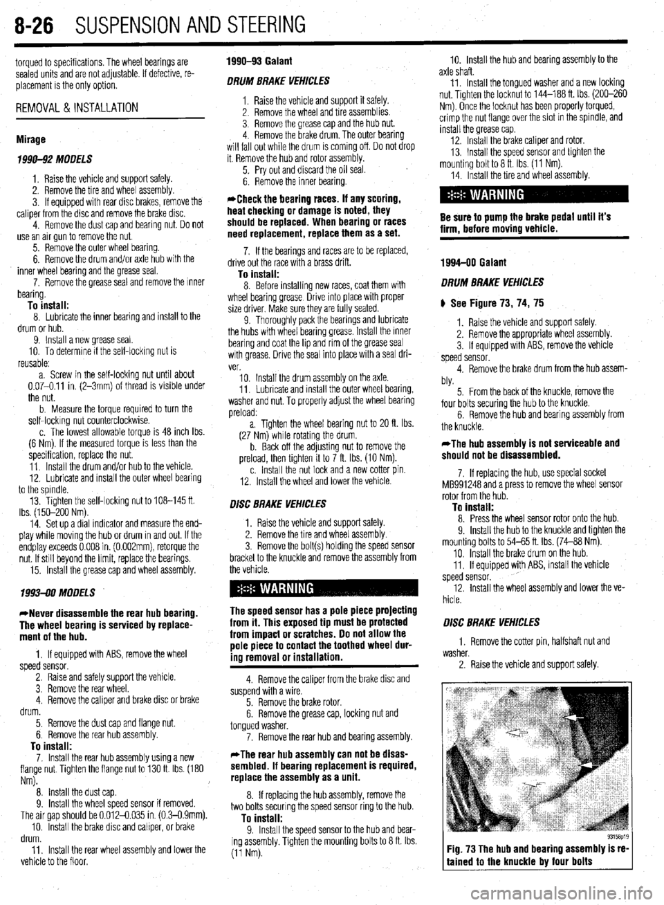
Fig. 73 The hub and bearing assembly is re-
tained to the knuckle by four bolts
Page 329 of 408
SUSPENSION AND STEERING 8-33
*Matchmark the pinion input shaft of the
rack to the lower steering column joint for in-
stallation purposes.
6. Remove the pinch bolt holding the lower
steering column joint to the rack and pinion input
shaft.
7. Remove the cotter pins and disconnect the tie
rod ends from the steering knuckle.
8. Remove the rack and pinion steering assem-
bly and its rubber mounts from the right side of the
vehicle.
To install: 9. Align the matchmarks of the input shaft and
install the rack to the vehicle.
10. Secure the rack using the retainer clamps and
bolts. Tighten the bolts to 51 ft. Ibs. (70 Nm).
11. Tighten the steering column pinch bolt to 13
ft. Ibs. (18 Nm).
12. Install the center member.
13. Install the front exhaust pipe.
14. Connect the HO$ sensor.
15. Connect the tie rod ends to the steering
knuckles and tighten the castle nuts to 25 ft. Ibs. (34
Nm). Install new cotter pins.
16. Install the wheels and connect the negative
battery cable.
17. Have a front end alignment performed.
REMOVAL &INSTALLATION
Diamante
FRONT
*Prior to removal of the steering gear box,
center the front wheels and remove the igni-
tion key. Failure to do so may damage the
SRS clock spring and render SRS system in-
operative.
1. Disconnect the negative battery cable.
2. Disconnect the front exhaust pipe.
3. If equipped with AWD, remove the transfer
case assembly.
4. Remove the bolt holding the lower steering
column joint to the rack and pinion input shaft.
5. Remove the cotter pins and disconnect the tie
rod ends.
6. Remove the left and right frame members.
7. Remove the stabilizer bar bracket.
8. If equipped with four-wheel steering, discon-
nect the lines going to the rear pump.
9. Remove the rack and pinion steering assem-
bly and its rubber mounts. Move the rack to the right
to remove it from the crossmember.
To install: IO. Install the rack and mounting bolts. Tighten
the bolts to 51 ft. Ibs. (70 Nm). When installing the
rubber rack mounts, align the projection of the
mounting rubber with the indentation in the cross:
member. Install the pinch bolt.
11. Connect the pressure and return lines to the
rack and to the rear pump, if equipped.
12. Install the frame members and tighten the
bolts to 43-51 ft. Ibs. (60-70 Nm).
13. Connect the tie rods and install new cotter
pins. 14. Install the transfer case and front exhaust
pipe.
15. Refill the reservoir and bleed the system.
16. Have a front end alignment performed.
REAR
1. Disconnect the negative battery cable.
2. Raise the vehicle and support safely.
3. Drain the power steering fluid.
4. Remove the main muffler assembly.
5. Remove the rear shock absorber lower
mounting bolts.
6. Using the proper equipment, support the
weight of the rear differential. Remove the 2 small
crossmember brackets.
7. Remove the large self-locking crossmember
mounting nuts on the differential side.
8. Remove the oil line clamp bolts.
9. Remove the pressure tubes.
IO. Hold the tie rod ends stationary and remove
the tie rod end nuts. Remove the tie rod ends from
the trailing arms.
11. Remove the mounting bolts and remove the
rear steering gear.
To install: 12. Secure the unit to the crossmember. Move
the power cylinder piston rod over its full stroke to
determine its neutral position.
13. Align the tie rod ends with the holes in the
trailing arms and install the nuts. Adjust the length of
the tie rods with the nuts if necessary. The difference
in length between the 2 tie rod ends should not ex-
ceed 0.04 in. (1 mm). The nuts’ torque specification is
42 ft. Ibs. (58 Nm).
14. Replace the O-rings and install the pressure
tubes. Clamp in place.
15. Install the large self-locking crossmember
mounting nuts on the differential side. Tighten to
80-94 ft. Ibs. (110-130 Nm).
16. Remove the support equipment.
17. Install the 2 small crossmember brackets.
18. Install the shock mounting bolts.
19. Install the muffler assembly.
20. Refill the reservoir and bleed the system.
21. Have a front end alignment performed. _
Galant
1990-93 MODELS
1. Disconnect the negative battery cable.
2. Drain the power steering fluid.
3. Raise the vehicle and support safely.
4. Remove the bolt holding lower steering col-
umn joint to the rack and pinion input shaft.
5. Remove the transfer case, if equipped.
6. Remove the cotter pins and using the proper
tools, separate the tie rod ends from the steering
knuckle.
7. Locate the triangular brace near the stabilizer
bar brackets on the crossmember and remove both
the brace and the stabilizer bar bracket.
8. Support the center crossmember.
9. Remove the through-bolt from the round roll
stopper and remove the rear bolts from the center
crossmember.
10. Disconnect the front exhaust pipe, if
equipped with FWD.
11. Disconnect the power steering fluid pressure
pipe and return hose from the rack fittings. Plug the
fittings to prevent excess fluid leakage. 12. Lower the crossmember slightly.
13. Remove the rack and pinion steering assem-
bly and its rubber mounts. Move the rack to the right
to remove from the crossmember. Tilt the assembly
downward and remove from the left side of the vehi-
cle. Use caution to avoid damaging the boots.
To install: 14. Install the rack and install the mounting bolts. Tighten the mounting bolts to 43-58 ft. Ibs. (60-80
Nm). When installing the rubber rack mounts, align
the projection of the mounting rubber with the inden-
tation in the crossmember.
15. Connect the power steering fluid lines to the
rack.
16. Connect the exhaust pipe, if removed.
17. Raise the crossmember into position. Install
the center member mounting bolts and tighten to 72
ft. Ibs. (100 Nm). Install the roll stopper bolt and new
nut. Tighten nut to 47 ft. Ibs. (65 Nm).
18. Install the stabilizer bar brackets and brace.
19. Connect the tie rod ends and tighten nuts to
25 ft. Ibs. (34 Nm).
20. Install the transfer case, if removed. Check
and fill fluid.
21. Refill the reservoir with power steering fluid
and bleed the system.
22. Have a front end alignment performed.
1994-M MODELS
+ See Figure 96
Prior to removal of the steering gear box,
center the front wheels and remove the igni-
tion key. Failure to do so may damage the
SRS clock spring and render SRS system in-
operative.
1. Disconnect the negative battery cable.
2. Raise and properly support the vehicle.
3. Remove both front wheel assemblies.
4. Remove the bolt holding lower steering col-
umn joint to the rack and pinion input shaft.
5. Remove the stabilizer bar.
6. Remove the cotter pins, and using joint sepa-
rator MB991 113 or equivalent, disconnect the tie rod
ends from the steering knuckle.
7. On vehicles equipped with Electronic Control
Power steering (EPS), detach the wiring harness from
the solenoid connector.
8. Locate the two triangular braces near the
crossmember and remove both.
9. Support the center crossmember. Remove the
through-bolt from the front round roll stopper and re-
move the bolts securing the center crossmember.
10. Remove the center crossmember. ,
Il. Properly support the engine and remove the
rear roll stopper through-bolt.
12. Disconnect the power steering fluid pressure
pipe and return hose from the rack fittings. Plug the
fittings to prevent excessive fluid leakage.
13. Remove the clamp bolts and the two bolts se-
curing the rack assembly to the chassis.
14. Remove the rack and pinion steering assem-
bly and its rubber mounts.
*When removing the rack and pinion as-
sembly, tilt the assembly to the vehicle side
of the compression lower arm and remove
from the left side of the vehicle.
Page 334 of 408
- 8-38 SUSPENSION AND STEERING
11. Adjust the power steering belt for proper ten-
sion and tighten the adjusting bolts.
12. Reconnect the negative battery cable.
13. Refill the reservoir and bleed the system.
3. Of EIJGINE
1. Disconnect the battery negative cable. 2. Disconnect the return fluid line. Remove the
reservoir cap and allow the return line to drain the
fluid from the reservoir. If the fluid is contaminated,
disconnect the ignition high tension cable and crank
the engine several times to drain the fluid from the
gear box.
3. Remove the power steering pump drive belt.
4. Remove the pressure switch connector from
the side of the pump.
5. If the alternator is located under the oil pump,
cover it with a shop towel to protect it from oil.
6. Disconnect the high pressure hose and the
return hose from the pump.
7. Remove the pump drive belt and unbolt the
pump from its bracket and remove the pump.
To install: 8. Install the pump, *rap the belt around the
pulley and tighten the bolts that secure the pump to
17 ft. Ibs. (24 Nm).
9. Replace the O-rings and connect the high
pressure hose. Connect the pressure line so the
notch in the fitting aligns and contacts the pump’s
guide bracket. Tighten the mounting nut with lock-
washer to 17 ft. Ibs. (24 Nm).
IO. Using a new hose clamp, connect the return
line.
11. Attach the pressure switch connector.
12. Adjust the belt tension and tighten the
adjust- ing bolts.
13. Refill the reservoir and bleed the system.
Diamante *
FRONT
. 1. Disconnect the battery negative cable. 2. Disconnect the return fluid line. Remove the
reservoir cap and allow the return line to drain the
fluid from the reservoir. If the fluid is contaminated,
disconnect the ignition high tension cable and crank
the engine several times to drain the fluid from the
gearbox.
3. Remove the power steering pump drive belt.
4. Remove the pressure switch connector from
the side of the pump.
5. If the alternator is located under the oil pump,
cover it with a shop towel to protect it from oil.
6. Disconnect the high pressure hose and the
return hose from the pump.
7. Remove the pump drive belt and unbolt the
pump from its bracket and remove the pump.
To install: 8. Install the pump, wrap the belt around the
pulley and tighten the bolts that secure the pump to
17 ft. Ibs. (24 Nm).
9. Replace the O-rings and connect the high
pressure hose. Connect the pressure line so the
notch in the fitting aligns and contacts the pump’s
guide bracket. Tighten the mounting nut with lock-
washer to 17 ft. Ibs. (24 Nm).
10. Using a new hose clamp, connect the return
line.
Il. Attach the pressure switch connector.
12. Adjust the belt tension and tighten the adjust-
ing bolts.
13. Refill the reservoir and bleed the system.
REAR
1. Disconnect the negative battery cable.
2. Drain the power steering fluid.
3. Remove the rear power steering pump heat
protector, located on the engine side of the differen-
tial on the transaxle.
4. Disconnect the pressure line from the pump.
5. Disconnect the suction hose from the pump.
6. Remove the mounting bolts and remove the
pump from the transaxle.
44
33
REMOVAL STEPS
5. POWER STEERING PUMP
BRACKET STAY
6. OIL PUMP 1. DRIVE-BELT
2. SUCTION HOSE I ’ 3. PRESSURE HOSE
4. PRESSURE SWITCH
CONNECTOR
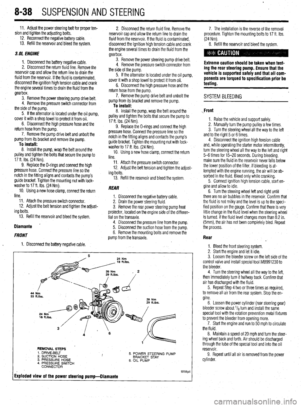
Exploded view of the power steering pump-Diamante
. 93158ga5
7. The installation is the reverse of the removal
procedure. Tighten the mounting bolts to 17 ft. Ibs.
(24 Nm).
8. Refill the reservoir and bleed the system.
Extreme caution should be taken when test-
ing the rear steering pump. Ensure that the
vehicle is supported safely and that all com-
ponents are torqued to specification prior be
testing.
. SYSTEM BLEEDING
,Front
1. Raise the vehicle and support safely.
2. Manually turn the pump pulley a few times.
3. Turn the steering wheel all the way to the left
and to the right 5 or 6 times.
4. Disconnect the ignition high tension cable
and, while operating the starter motor intermittently,
turn the steering wheel all the way to the letI and right
5-6 times for 15-20 seconds. During bleeding,
make sure the fluid in the reservoir never falls below
the lower position of the filter. If bleeding is at-
tempted with the engine running, the air will be ab-
sorbed in the fluid. Bleed only while cranking.
5. Connect ignition high tension cable, start en-
gine and allow to idle.
6. Turn the steering wheel left and right until
there are no air bubbles in the reservoir. Confirm that
the fluid is not milky and the level is up to the speci-
fied position on the gauge. Confirm that there is very
little change in the fluid level when the steering wheel
is turned. If the fluid level changes more than 0.2 in.
(5mm), the air has not been completely bled. Repeat
the process.
Rear
.
1. Bleed the front steering system.
2. Start the engine and let it idle.
3. Loosen the bleeder screw on the left side of the
control valve and install special tool MB991230 to
the bleeder.
4. Turn the steering wheel all the way to the left,
then immediately turn it halfway back. Confirm that
air has discharged with the fluid.
5. Repeat Step 4 two or three times as required,
to remove all air from the rear system. Stop the en-
gine.
6. Loosen the power cylinder (rear steering gear)
bleeder screw about I/* turn and install the same
special tool with the rotation prevention metal fixtures
to prevent the bleeder from opening more.
7. Start the engine and run to 50 mph to circulate
the fluid.
8. Maintain a speed of 20 mph and turn the steer-
ing wheel back and forth. Air should be discharged ,
through the tube of the special tool and into the oil
reservoir.
9. Repeat until all air is removed from the power
cylinder.
Page 335 of 408
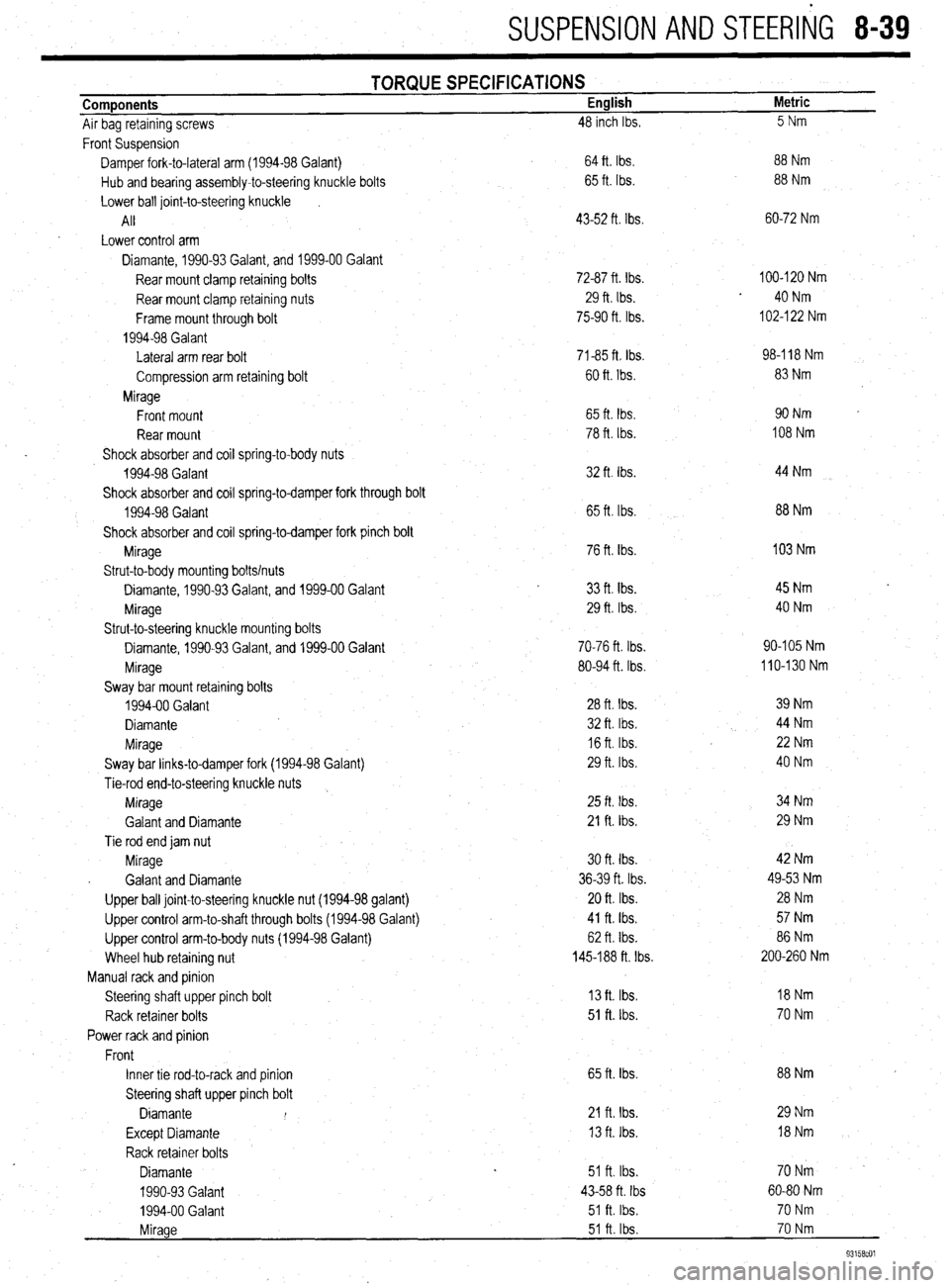
SUSPENSION AND STEERliG 8-39
Components
Air bag retaining screws TORQUE SPECIFICATIONS English
48 inch Ibs. Metric
5Nm
Front Suspension
Damper fork-to-lateral arm (1994-98 Galant)
Hub and bearing assembly-to-steering knuckle bolts
Lower ball joint-to-steering knuckle
I
All
Lower control arm
Diamante, 1990-93 Galant, and 1999-00 Galant
Rear mount clamp retaining bolts
Rear mount clamp retaining nuts
Frame mount through bolt
1994-98 Galant
Lateral arm rear bolt
Compression arm retaining bolt
Mirage
Front mount
Rear mount
Shock absorber and coil spring-to-body nuts
1994-98 Galant
Shock absorber and coil spring-to-damper fork through bolt
1994-98 Galant
Shock absorber and coil spring-to-damper fork pinch bolt
Mirage
Strut-to-body mounting bolts/nuts
Diamante, 1990-93 Galant, and 1999-00 Galant
Mirage
Strut-to-steering knuckle mounting bolts
Diamante, 1990-93 Galant, and 1999-00 Galant
Mirage
Sway bar mount retaining bolts
1994-00 Galant
Diamante
Mirage
Sway bar links-to-damper fork (1994-98 Galant)
Tie-rod end-to-steering knuckle nuts
Mirage
Galant and Diamante
Tie rod end jam nut
Mirage
. Galant and Diamante
Upper ball joint-to-steering knuckle nut (1994-98 galant)
Upper control arm-to-shaft through bolts (1994-98 Galant)
Upper control arm-to-body nuts (1994-98 Galant)
Wheel hub retaining nut
Manual rack and pinion
Steering shaft upper pinch bolt
Rack retainer bolts
Power rack and pinion
Front
Inner tie rod-to-rack and pinion
Steering shaft upper pinch bolt
Diamante I
Except Diamante
Rack retainer bolts
Diamante
1990-93 Galant
1994-00 Galant . 64 ft. Ibs.
65 ft. Ibs.
43-52 ft. Ibs.
72-87 ft. Ibs.
29 ft. Ibs.
75-90 ft. Ibs.
71-85 ft Ibs.
60 ft. Ibs.
65 ft. tbs.
78 ft. Ibs.
32 ft. Ibs.
65 ft. Ibs.
76 ft. Ibs.
33
ft. tbs. 29 ft. Ibs.
70-76 ft. Ibs.
80-94 ft. Ibs.
28 ft. Ibs.
32 ft. Ibs.
16 ft. Ibs.
29 ft. Ibs
25 ft. Ibs.
21 ft. Ibs.
30 ft. tbs.
36-39 ft. Ibs.
20 ft. Ibs.
41 ft. Ibs.
62 ft. Ibs.
145-188 ft. Ibs.
13 ft. Ibs.
51 ft. lbs.
65 ft. Ibs.
21 fta Ibs.
13 ft. Ibs.
51 ft. Ibs.
43-58 ft. Ibs
51 ft. Ibs. 88 Nm
88 Nm
60-72 Nm
100-120 Nm
40 Nm
102-l 22 Nm
98-l 18 Nm
83 Nm
90Nm
108 Nm
44 Nm
88 Nm
103 Nm
45 Nm
40 Nm
90-105 Nm
110-130 Nm
39 Nm
44 Nm
22 Nm
40 Nm
34 Nm
29 Nm
42 Nm
49-53 Nm
28 Nm
57 Nm
86 Nm
200-260 Nm
18Nm
70 Nm
88 Nm
29 Nm
l8Nm
70Nm -
60-80 Nm
70 Nm
70 Nm
93158cOl
Mirage 51 ft. Ibs.
Page 336 of 408
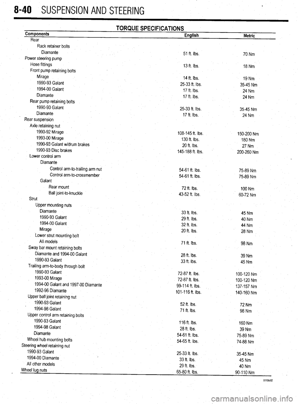
8-40 SUSPENSION AND STEERING
Components
Rear TORQUE SPECIFICATIONS English
Metric
Rack retainer bolts
Control arm-to-trailing arm nut Diamante
Power steering pump
Hose fittings
Front pump retaining bolts
Mirage
1990-93 Galant
1994-00 Galant
Diamante
Rear pump retaining bolts
1990-93 Galant
Diamante
Rear suspension
Axle retaining nut
1990-92 Mirage
1993-00 Mirage
1990-93 Galant w/drum brakes
1990-93 Disc brakes
Lower control arm
Diamante 51 ft. Ibs
13 ft. Ibs,
14 ft. Ibs.
25-33 ft. tbs.
17 ft. tbs.
17 ft. Ibs.
25-33 ft. Ibs.
17 ft. Ibs.
108-145 ft. Ibs.
130 ft. Ibs.
20 ft. Ibs.
145-188 ft. Ibs.
54-61 ft. Ibs. 54-61 ft. Ibs.
72 ft. Ibs.
43-52 ft. Ibs.
33 ft. Ibs.
29 ft. Ibs.
32 ft. Ibs.
20 ft. Ibs.
71 ft. Ibs.
28 ft. Ibs.
33 ft. tbs.
72-87 ft. Ibs.
72-87 ft. Ibs.
99414 ft. Ibs.
101-116 ft. Ibs.
52 ft. Ibs.
71 ft. Ibs.
116 ft. Ibs.
28 ft. Ibs.
54-61 ft. Ibs.
54-65 ft. Ibs.
25-33 ft. Ibs.
33 ft. Ibs.
29 ft Ibs.
65-80 ft. Ibs. Control arm-to-crossmember
Galant
Rear mount
Ball joint-to-knuckle
Strut
Upper mounting nuts
Diamante
1990-93 Galant
1994-00 Galant
Mirage
Lower strut mounting bolt
All models
Sway bar mount retaining bolts
Diamante and 1994-00 Galant
1990-93 Galant
Trailing arm-to-body through bolt
1990-93 Galant
1993-00 Mirage
1994-00 Galant and 1997-00 Diamante
1992-96 Diamante
Upper ball joint retaining nut
1990-93 Galant
1994-98 Galan t
Upper control arm retaining bolts
1990-93 Galant
1994-98 Galant
Diamante
Wheel hub mounting bolts
Steering wheel retaining nut
1990-93 Galant
1994-00 Diamante
All other models 70 Nm
18 Nm
19 Nm
35-45 Nm
24 Nm
24 Nm
35-45 Nm
24 Nm
150-200 Nm
180 Nm
27 Nm
200-260 Nm
75-89 Nm
75-89 Nm
100 Nm
60-72 Nm
45 Nm
40 Nm
44 Nm
28 Nm
98 Nm
39 Nm
45 Nm
100-120 Nm
100-120 Nm
137-157 Nm
140-160 Nm
72Nm *
98 Nm
160 Nm
39 Nm
75-89 Nm
74-88 Nm
35-45 Nm
45 Nm
40 Nm
90-l IO Nm
93158co2
Wheel lug nuts
Page 344 of 408
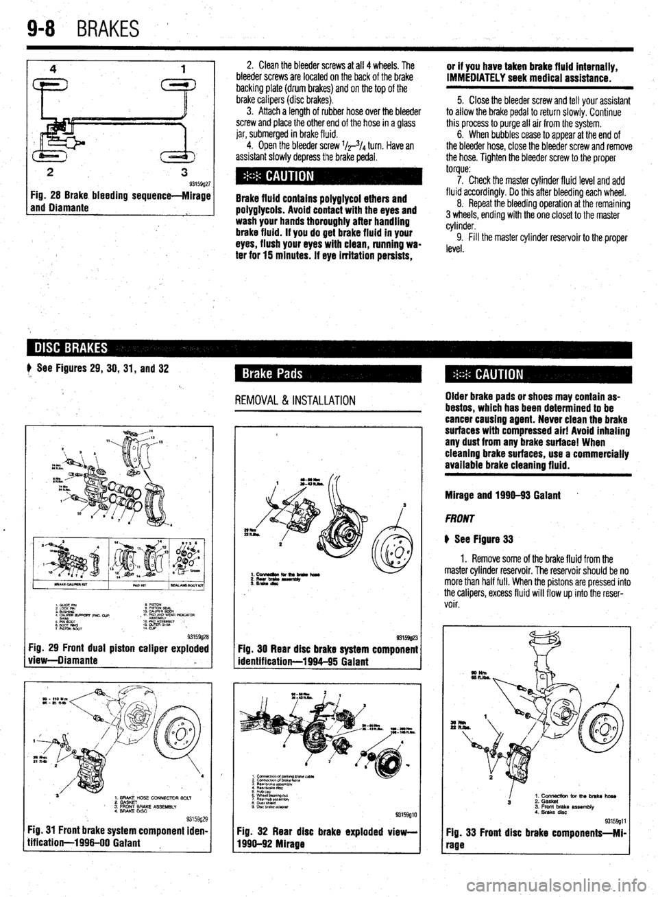
9-8 BRAKES
2
3 93159g27 Fig. 28 Brake bleeding sequence-Mirage
and Diamante
1
2, Clean the bleeder screws at all 4 wheels. The
bleeder screws are located on the back of the brake
backing plate (drum brakes) and on the top of the
brake calipers (disc
brakes). 3. Attach a length of rubber hose over the bleeder
screw and place the other end of the hose in a glass
jar, submerged in brake fluid.
4. Open the bleeder screw l/r3/4 turn. Have an
assistant slowly depress the brake pedal.
Brake fluid contains polyglycol ethers and
poiygiycois. Avoid contact with the eyes and
wash your hands thoroughly after handling
brake fluid. if you do get brake fluid in your
eyes, flush your eyes with clean, running wa-
ter for 15 minutes. if eye irritation persists, or if you have taken brake fluid internally,
IMMEDIATELY seek medical assistance.
5. Close the bleeder screw and tell your assistant
to allow the brake pedal to return slowly. Continue
this process to purge all air from the system.
6. When bubbles cease to appear at the end of
the bleeder hose, close the bleeder screw and remove
the hose. Tighten the bleeder screw to the proper
torque:
7. Check the master cylinder fluid level and add
fluid accordingly. Do this after bleeding each wheel,
8. Repeat the bleeding operation at the remaining
3 wheels, ending with the one closet to the master
cylinder.
9. Fill the master cylinder reservoir to the proper
level.
# See Figures 29, 30, 31, and 32
REMOVAL &INSTALLATION
.
I. C”lDE PIN 8 mm
2 LdcK Pm 9 PlSToN SEAL
3 WSHINO 10 WPER BODY
4 CALIPER 9lJPwRT ,pM. cue
sH’YlcYaT , 11 PmE~~yvEm INLKATclR
: EiT Rim 12 PAD As&&w
7 PWON mm ;: w&E” SHlM ,
93159g28 Fig. 29 Front dual piston caliper exploded
view-Diamante ‘a
L
1. BRAKE HOSE CONNECTOR BOLT
2. GASKET
’ 3. FRONT BRAKE ASSEMBLY
4. BRAKE DISC
93159g; Fig. 31 Front brake system component iden
tification-1996-00 Gaiant !9
I- 93159g23
Fig. 30 Rear disc brake system component
identification-1994-95 Galant
3 Rear brake ar?.embiy
4 Rear Drake dnc
5 Hubcap
6 Wheel baanng tit
7 Flew hub assemblv
8 chlstshteki
9 DISC brake adapter
93159glC
Fig. 32 Rear disc brake exploded view-
1996-92 Mirage Older brake pads or shoes may contain as-
bestos, which has been determined to be
cancer causing agent. Never clean the brake
surfaces with compressed air! Avoid inhaling
any dust from any brake surface! When
cieanlng brake surfaces, use a commercially
available brake cleaning fluid.
Mirage and 1990-93 Gaiant *
FRONT
@ See Figure 33
1. Remove some of the brake fluid from the
master cylinder reservoir. The reservoir should be no
more than half full. When the pistons are pressed into
the calipers, excess fluid will flow up into the reser-
voir.
I
1. Cons for the brake hose
3 2. Gasket
3. Front brake assembly
4. Brake disc
93159911
Fig. 33 Front disc brake components-Mi-
rage
Page 348 of 408
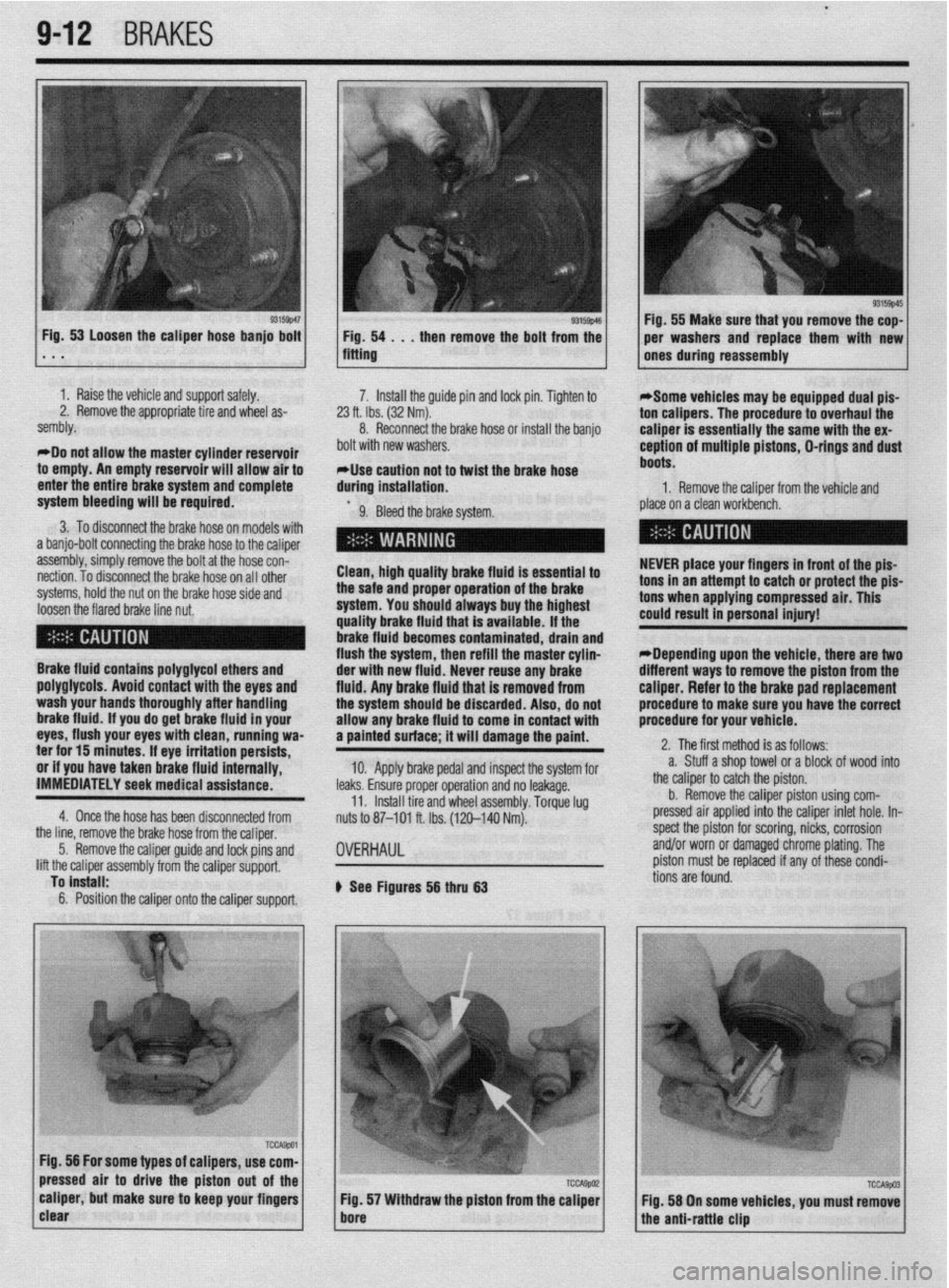
l
942 BRAKES
I 93155~46 Fig, 53 Loosen the caliper hose banjo bolt
1 Fig. 54 . . , then remove the bolt from the . * . fitting
1 I Raise the vehicle and support safely.
2. Remove the appropriate tire and wheel as-
sembly.
*Do not allow the master cylinder reservoir
to empty. An empty reservoir will allow air to
enter the entire brake system and complete 7. Install the guide pin and lock pin. Tighten to
23 ft. Ibs. (32 Nm).
8. Reconnect the brake hose of install the banjo
bolt with new washers.
*Use caution not to twist the brake hose
during installation.
system bleeding will be required.
9. Bleed the brake system.
3. To disconnect the brake hose on models with
a banjo-bolt connecting the brake hose to the caliper
assembly, simply remove the bolt at the hose con-
nection. To disconnect the brake hose on all other
systems, hold the nut on the brake hose side and
loosen the flared brake line nut. Clean, high quality brake fluid is essential to
the safe and proper operation of the brake
system. You should always buy the highest
quality brake fluid that is available. If the
brake fluid becomes contaminated, drain and
flush the system, then refill the master cylin-
Brake fluid contains polyglycol ethers and
poly~lycols. Avoid contact with the eves and
wash your hands thoroughly after handling
brake fluid. if you do get brake fluid In your
eyes, flush your eyes with clean, running wa-
ter for 15 minutes. If eye irritation persists,
or if you have taken brake fluid internally,
IMMEDIATELY seek medical assistance.
4. Once the hose has been disconnected from der with new fluid. Never reuse any brake
fluid. Anv brake fluid that is removed from
the systum should be discarded. Also, do not
allow any brake fluid to come in contact with
a painted surface; it will damage the paint.
10. Apply brake pedal and inspect the system for
leaks. Ensure proper operation and no leakage.
11. Install tire and wheel assembly. Torque lug
nuts to 87-101 ft. Ibs. (120-140 Nm).
the line, remove the brake hose from the caliper,
5. Remove the caliper guide and lock pins and
lift the caliper assembly from the caliper support,
To install:
6. Position the caliper onto the caliper support.
OVERHAUL
b See Figures 56 thru 63 1 Fig. 55 Make sure that you remove the cop-
per washers and replace them with new
ones during reassembly
*Some vehicles may be equipped dual pis-
ton calipers. The procedure to overhaul the
caliper is essentially the same with the ex-
ception of multiple pistons, D-rings and dust
boots.
1. Remove the caliper from the vehicle and
place on a clean workbench.
NEVER place your fingers in front of the pis-
tons in an attempt to catch or protect the pis-
tons when applying compressed air. This
could result in personal injury!
*Depending upon the vehicle, there are two
different ways to remove the piston from the
caliper. Refer to the brake pad replacement
procedure to make sure you have the correct
procedure for your vehicle.
2. The first method is as follows:
a. Stuff a shop towel or a block of wood into
the caliper to catch the piston.
b. Remove the caliper piston using com-
pressed air applied into the caliper inlet hole. In-
spect the piston for scoring, nicks, corrosion
and/or worn or damaged chrome plating. The
piston must be replaced if any of these condi-
tions are found.