1900 MITSUBISHI DIAMANTE light
[x] Cancel search: lightPage 55 of 408
.
2-8 ENGINEELECTRICAL
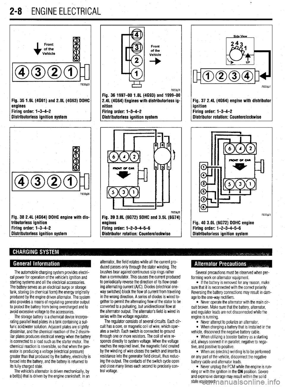
Front
of the
Vehicle
Fig. 35 1.61(4661) and 2.OL (4663) DDHC
engines
Firing order: l-3-4-2
Distributorless ignition system
Fig. 36 2.4L (4664) DDHC engine with dis-
lributorless ignition
Firing order: l-3-4-2
gistributorless ignition system
Front
of the
Vehicle
+
Fig. 36 1997-00 1.6L (4693) and 1999-00
2.41(4664) Engines with distributorless ig-
nition
Firing order: l-3-4-2
Distributorless ignition system
792!33g26 Fig. 39 3.OL (6672) SDHC and 3.5L (6674)
engines
Firing order: l-2-3-65-6
Distributor rotation: Counterclockwise Fig. 37 2.4L (4664) engine with distributor
ignition
Firing order: l-3-4-2
Distributor rotation: Counterclockwise
:ig. 40 3.OL (6672) DDHC engine
Yring order: l-2-3-4-5-6
Iistributorless ignition system
The automobile charging system provides electri-
cal power for operation of the vehicle’s ignition and
starting systems and all the electrical accessories.
The battery serves as an electrical surge or storage
tank, storing (in chemical form) the energy originally
produced by the engine driven alternator. The system
also provides a means of regulating generator output
to protect the battery from being overcharged and to
avoid excessive voltage to the accessories.
The storage battery IS a chemical device incorpo-
rating parallel lead plates in a tank containing a sul-
furic acid/water solution. Adjacent plates are slightly
dissimilar, and the chemical reaction of the 2 dissim-
ilar plates produces electrical energy when the battery
is connected to a load such as the starter motor. The
chemical reaction is reversible, so that when the gen-
erator IS producing a voltage (electrical pressure)
greater than that produced by the battery, electricity is
forced into the battery, and the battery is returned to
its fully charged state.
The vehicle’s alternator is driven mechanically, by
a belt(s) that is driven by the engine crankshaft. In an alternator, the field rotates while all the current pro-
duced passes only through the stator winding. The
brushes bear against continuous slip rings rather
than a commutator. This causes the current produced
to periodically reverse the direction of its flow creat-
ing alternating current (A/C). Diodes (electrical one-
way switches) block the flow of current from traveling
in the wrong direction. A series of diodes is wired to-
gether to permit the alternating flow of the stator to be
converted to a pulsating, but unidirectional flow at
the alternator output, The alternators field is wired in
series with the voltage regulator.
The regulator consists of several circuits. Each cir-
cuit has a core, or magnetic coil of wire, which oper-
ates a switch. Each switch is connected to ground
through one or more resistors. The coil of wire re-
sponds directly to system voltage. When the voltage
reaches the required level, the magnetic field created
by the winding of wire closes the switch and inserts a
resistance into the generator field circuit, thus reduc-
ing the output. The contacts of the switch cycle open
and close many times each second to precisely con-
trol voltage. Several precautions must be observed when per-
forming work on alternator equipment.
l If the battery is removed for any reason, make
sure that it is reconnected with the correct polarity.
Reversing the battery connections may result In dam-
age to the one-way rectifiers.
l Never operate the alternator with the main cir-
cuit broken. Make sure that the battery, alternator,
and regulator leads are not disconnected while the
engine is running.
l Never attempt to polarize an alternator. l When charging a battery that is installed in the
vehicle, disconnect the negative battery cable.
l When utilizing a booster battery as a starting
aid, always connect it in parallel; negatrve to nega-
tive, and positive to positrve.
l When arc (electric) welding is to be performed
on any part of the vehicle, disconnect the negative
battery cable and alternator leads.
l Never unplug the PCM while the engine is run-
ning or with the ignition in the ON position. Severe
and expensive damage may result within the solid
state equipment.
Page 56 of 408
ENGlNEELECTRldAL 2-9
TESTING
Voltage Test able for use by customers. An alternator
bench test is the most definitive way to de-
termine the condition of your alternator.
REMOVAL&INSTALLATION
1. Make sure the engine is OFF, and turn the 1.51,1.61, 1.6L, 2.OL and 2.4L Engines
headlights on for 15-20 seconds to remove any sur-
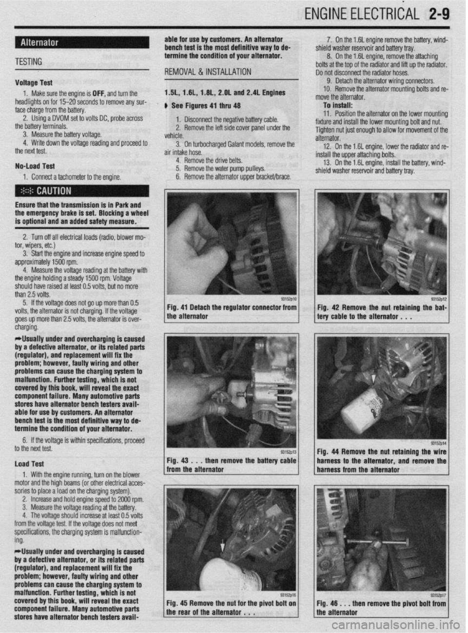
face charge from the battery. , See Figures 4, thru 48
2. Using a DVOM set to volts DC, probe across
1. Disconnect the negative battery cable.
the battery terminals.
3. Measure the battery voltage. 2. Remove the left side cover panel under the
vehicle.
4. Write down the voltage reading and proceed to
3. On turbocharaed Galant models, remove the
the next test.
air intake hose. -
No-load Test
1. Connect a tachometer to the engine. 4. Remove the drive belts.
5. Remove the water pump pulleys.
6. Remove the alternator upper bracket/brace.
Ensure that the transmission
is in Park and the emergency brake is set. Blocking a wheel
is optional and an added safety measure.
2. Turn off all electrical loads (radio, blower mo-
tor, wipers, etc.)
3. Start the engine and increase engine speed to
approximately 1500 rpm.
4. Measure the voltage reading at the battery with
the engine holding a steady 1500 rpm. Voltage
should have raised at least 0.5 volts, but no more
than 2.5 volts.
5. If the voltage does not go up more than 0.5
volts, the alternator is not charging. If the voltage
goes up more than 2.5 volts, the alternator is over-
* 7. On the 1.6L engine remove the battery, wind-
shield washer reservoir and battery tray.
8. On the 1.6L engine, remove the attaching
bolts at the top of the radiator and lift up the radiator.
Do not disconnect the radiator hoses.
9. Detach the alternator wiring connectors.
10. Remove the alternator mounting bolts and re-
move the alternator.
To install:
11. Position the alternator on the lower mountina
fixture and install the lower mounting bolt and nut. U
Tighten nut just enough to allow for movement of the
alternator.
12. On the 1.6L engine, lower the radiator and re-
install the upper attaching bolts.
13. On the 1.6L engine, install the battery, wind-
shield washer reservoir and battery tray.
/ tery cable to the alternator . , . 93152p12 Fig 42 Remove the nut retaining the bat-
cnargmg.
*Usually under and overcharging is‘caused
by a defective alternator, or its related parts
(regulator), and replacement will fix the
problem; however, faulty wiring and other
problems can
cause the charging system to
malfunction. Further testing, which is not
covered by this book, will reveal the exact
component failure. Many automotive parts
stores have alternator bench testers avaii-
able for use by customers. An alternator
bench test is the most definitive way to de-
termine the condition of your alternator.
6. If the voltage is within specifications, proceeU
to the next test.
Load Test
1. With the engine running, turn on the blower
motor and the hioh beams (or other electrical acces-
sories to place aioad on the charging system). Fig. 44 Remove the nut retaining the
then remove the batte harness to the alternator and remov
,
2. Increase and hold engine speed to 2000 rpm.
3. Measure the voltage reading at the battery.
4. The voltage should increase at least 0.5 volts
from the voltage test. If the voltage does not meet
specifications, the charging system is malfunction-
ing.
*Usually under and overcharging is caused
by a defective alternator, or its related parts
(regulator), and replacement will fix the
problem; however, faulty wiring and other
problems can cause the charging system to
malfunction. Further testing, which is not
covered by this book, will reveal the exact
component failure. Many automotive parts
stores have alternator bench testers avaii-
93152p17 en remove the pivot bolt from
Page 59 of 408
.
2-12 ENGINEELECTRICAL
*This section describes the operating prina
ciples of sending units, warning lights and
gauges. Sensors which provide information
to the Enafne Control Unit (ECU) or Electronic
or Power&in Control Module (FCM/PCM) are
covered in Section 4 of this manual.
Instrument panels contain a number of indicating
devices (gauges and warning lights). These devices
are composed of two separate components. One is
the sending unit, mounted on the engine or other re-
mote part of the vehicle, and the other is the actual
gauge or light in the instrument panel.
Several types of sending units exist, however most
can be characterized as being either a pressure type
or a resistance type. Pressure type sending units
convert liquid pressure into an electrical signal which
is sent to the gauge. Resistance type sending units
are most often used to measure temperature and use
variable resistance to control the current flow back to
the indicatinq device. Both types of sendinq units are
connected inseries by a wimto the batteryithiough
the ignition switch). When the ignition is turned ON,
current flows from the battery through the indicating
device and on to the sending unit.
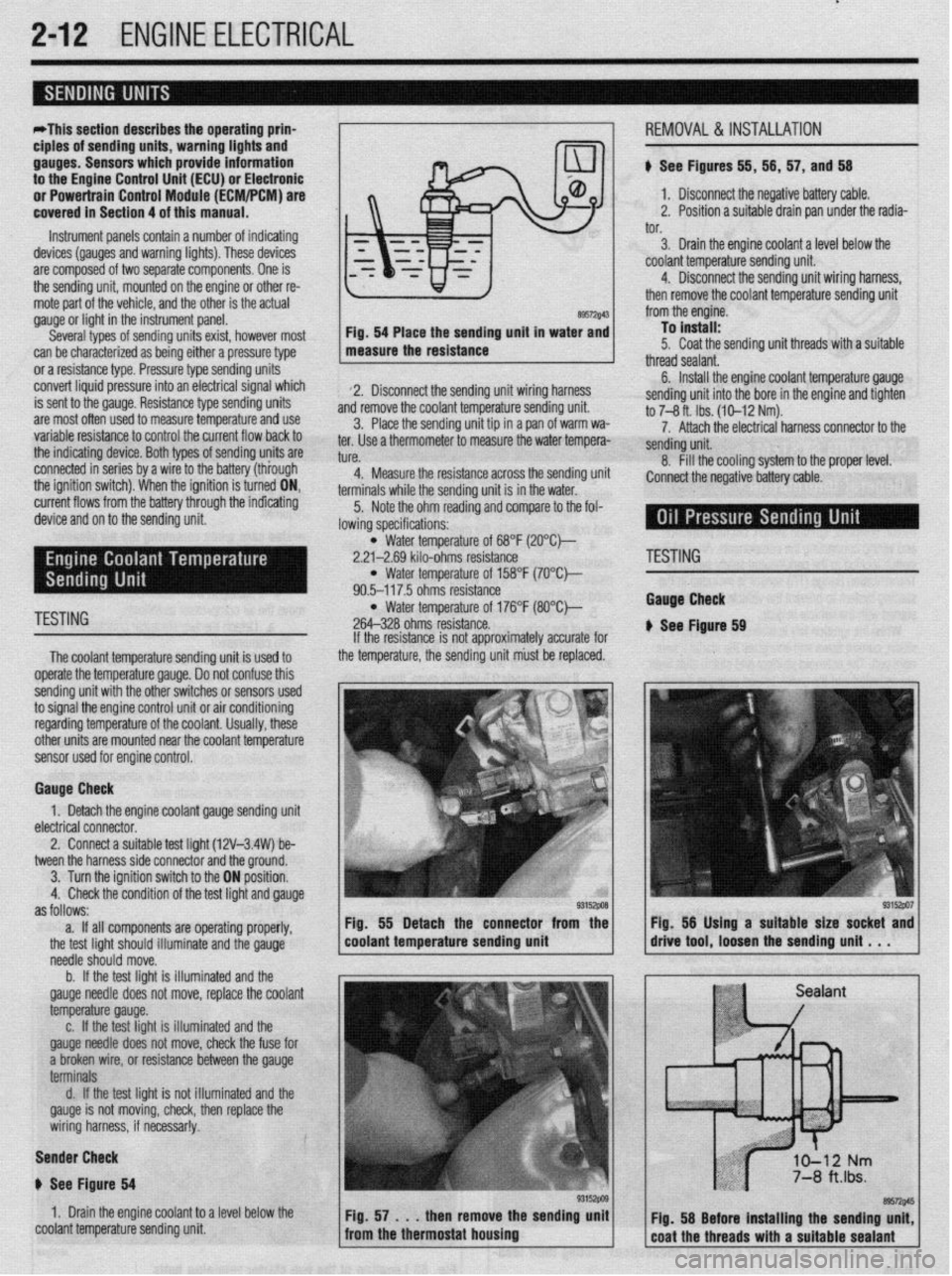
89572$43 Fig. 54 Place the sending unit in water and
measure the resistance
2. Disconnect the sending unit wiring harness
and remove the coolant temperature sending unit.
3. Place the sending unit tip in a pan of warm wa-
ter. Use a thermometer to measure the water tempera-
tl KP
L”,“.
4. Measure the resistance across the sending uni
terminals while the sending unit is in the water.
5. Note the ohm reading and compare to the fol-
lowing specifications: i, 56, 57, and 56
1. Disconnect the negative battery cable.
2. Position a suitable drain pan under the radia-
tor.
3. Drain the engine coolant a level below the
coolant temperature sending unit.
4. Disconnect the sending unit wiring harness,
then remove the coolant temperature sending unit
from the engine.
To install:
5. Coat the sending unit threads with a suitable
thread sealant.
6. Install the engine coolant temperature gauge
sending unit into the bore in the engine and tighten
to 7-8 ft. Ibs. (10-12 Nm).
7. Attach the electrical harness connector to the
sendina unit.
8. fill the cooling system to the proper level.
:onnect the negative battery cable.
l Water temperature of 68°F (2O”C)-
2.21-2.69 kilo-ohms resistance
l Water temperature of 158°F (7O’Ck
90.5-117.5 ohms resistance
TESTING l Water temperature of 176°F (8O”C)-
264-328 ohms resistance.
The coolant temperature sendina unit is used to
operate the temperature gauge. Donot confuse this
sending unit with the other switches or sensors used
to signal the engine control unit or air conditioning
regarding temperature of the coolant. Usually, these
other units are mounted near the coolant temoerature
sensor used for engine control. If the resistance is not approximately accurate for
the temperature, the sending unit must be replaced.
Gauge Check
1. Detach the engine coolant gauge sending unit
electrical connector.
2. Connect a suitable test liaht (12V-3.4W) be-
tween the harness side connector and the around.
I
3. Turn the ignition switch to the ON position.
4. Check the condition of the test light and gauge
as follows:
a. If all components are operating properly,
the test light should illuminate and the gauge
needle should move.
b. If the test light is illuminated and the
gauge needle does not move, replace the coolant
temperature gauge.
c. If the test light is illuminated and the
gauge needle does not move, check the fuse for
a broken wire, or resistance between the gauge
terminals
d. If the test light is not illuminated and the
gauge is not moving, check, then replace the
wiring harness, if necessar!y.
Sender Check
p See Figure 64
1. Drain the engine coolant to a level below the
coolant temperature sending unit Fig. 55 Detach the connector from the
coolant temperature sending unit
'ESTING
tauga Check
See Ftgure 69
Page 60 of 408
ENGINE ELECTRlCiL 2-13
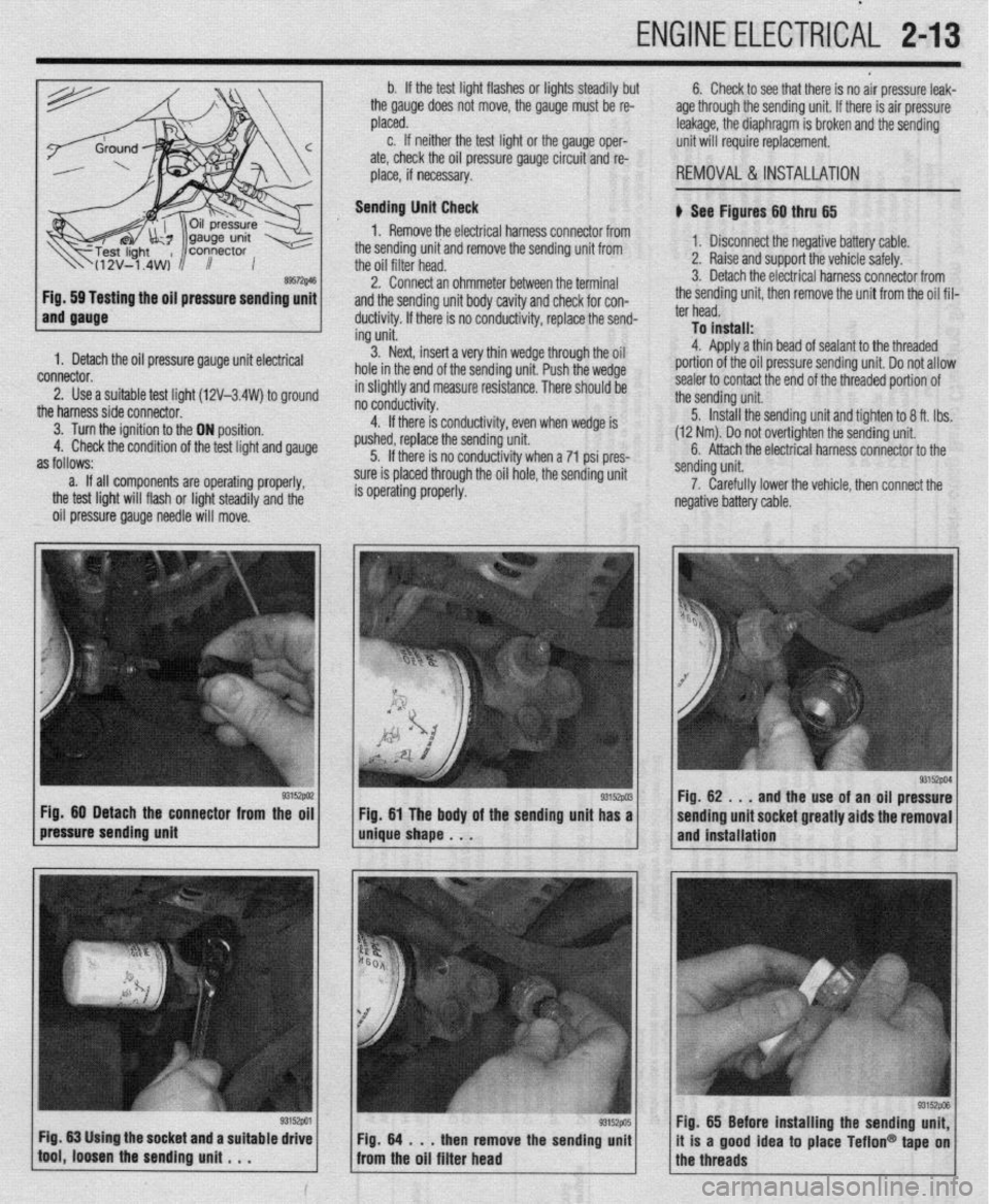
ing the oil pressure sending unit
1. Detach the oil pressure gauge unit electrical
connector.
2. Use a suitable test lioht (12V-3.4W) to around
the harnesssideconnecto~ ’ ’ -
3. Turn the ignition to the ON position.
4. Check the condition of the test light and gauge
as follows:
a. If all components are operating properly,
the test light will flash or light steadily and the
oil pressure gauge needle will move. b. If the test light flashes or lights steadily but
the gauge does not move, the gauge must be re-
placed.
c. If neither the test light or the gauge oper-
ate, check the oil pressure gauge circuit and re-
place, if necessary.
Sending Unit Check
1. Remove the electrical harness connector from
the sending unit and remove the sending unit from
the oil filter head.
2. Connect an ohmmeter between the terminal
and the sending unit body cavity and check for con-
ductivity. If there is no conductivity, replace the send-
ing unit.
3. Next, insert a very thin wedge through the oil
hole in the end of the sending unit. Push the wedge
in slightly and measure resistance. There should be
- - -- d . . . .
no conoucovey.
4. If there is conductivity, even when wedge is
pushed, replace the sending unit.
5. If there is no conductivity when a 71 psi pres-
sure is placed through the oil hole, the sending unit
is operating properly. 6. Check to see that there is no air pressure leak-
age through the sending unit. If there is air pressure
leakage, the diaphragm is broken and the sending
unit will require replacement.
REMOVAL &INSTALLATION
b See Figures 60 thru 65
1. Disconnect the negative battery cable.
2. Raise and support the vehicle safely.
3. Detach the electrical harness connector from
the sending unit, then remove the unit from the oil fil-
ter head.
To install:
4. Aoolv a thin bead of sealant to the threaded
portion of the oil pressure sending unit. Do not allow
sealer to contact the end of the threaded portion of
the sending unit.
5. Install the sending unit and tighten to 8 ft. tbs.
(12 Nm). Do not over-tighten the sending unit.
6. Attach the electrical harness connector to the
/pressure sending unit g3’9wi / m&e shape . . . Fig 60 Detach the connector from the oil
g3152w Fig 61 The body of the sending unit has a sending unit.
7. Carefully lower the vehicle, then connect the
negative battery cable.
93152PM Fig. 62 . , .
and the use of an oil pressure
sending unit socket greatly aids the removal
and installation
Fig. 65 Before installing the sending unit,
it is a good idea to place Teflon@ tape on
the threads
Page 61 of 408
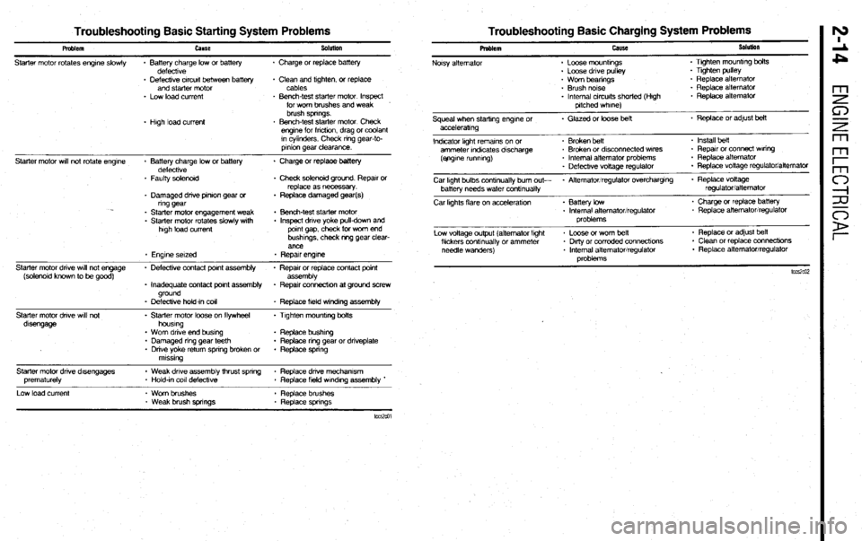
Troubleshooting Basic Starting System Problems Troubleshooting Basic Charging System Problems
Pmblem
Starter motor rotates engrne slowly cause
* Battery charge low or battery
defecttve Sobnlon
. Charge or replace battery
- Defective crrcurt between battery
and starter motor
* Low load current
* Hugh load current + Clean and ttghten, or replace
cables
* Bench-test starter motor Inspect
for wom brushes and weak
brush springs.
. Bench-test starter motor Check
engtne for fncbon, drag or coolant
rn cylinders. Check nng gear-to-
prnton gear clearance.
Starter motor wrll not rotate engrne
Starter motor dnve wrll not engage
(solenotd known to be good)
Starter motor dnve wtli not
dtsengage * Battery charge low or battery * Charge or replaoe battery
defecttve
* Faulty solenord . Check solenoid ground Reparr or
replace as necessary.
* Damaged drive pnron gear or * Replace damaged gear(s)
ring gear
* Starter motor engagement weak . Bench-test starter motor
. Starter motor rotates slowly wtth . Inspect dnve yoke pull-down and
high load current pornt gap, check for worn end
bushtngs. check m-g gear clear-
ance
. Engine setzed * Repatr engk7e
. Defecbve contact pant assembly * Reparr or replace contact pornt
assembly
. Inadequate contact pornt assembly + Repatr connectron at ground screw
ground
- Defeckve hold-In co11
* Replace field w~ndrng assembly
- Starter motor loose on flywheel . Ttghten mounttng bolts
houstng
. Worn drive end bustng . Replace bushtrg
* Damaged nng gear teeth . Replace ring gear or dnveplate
* Drive yoke return spnng broken or . Replace spnng
mtsstng
Starter motor dnve d&engages
prematurely
Low load current * Weak drive assembly thrust spnng * Replace dnve mechamsm
* Hold-tn co11 defeckve
. Replace field wtndtng assembly *
- Worn brushes . Replace brushes
* Weak brush springs * Replace spnngs Problem
Noisy alternator cause
* Loose mounbngs
. Loose drive pulley SoluIion
. Ttghten mountrng bolts
. Tighten pulley
. Worn beanngs
* Brush notse
* Internal circuits shorted (Hugh
pitched whrne) * Replace alternator
. Replace alternator
. Replace alternator
Squeal when starting engtne or . Glazed or loose belt * Replace or adfust belt
acceleratmg
Indicator light rematns on or . Broken belt . Install heft
ammeter rndrcates drscharge . Broken or dksconnected wares - Repatr or connect Waring
(ejrgrne runmng) * Internal aitemator problems * Replace alternator
. Defectrve voltage regulator . Replace vottage regulator/alternator
Car Irght bulbs contmually bum out- * Alternator/regulator overchargtng . Replace voltage
batter-v needs water conbnually regulatoriatternator
Car kghts flare on acceleratton . Battery low
. Internal alternator/regulator
problems * Charge or replace battery
. Replace alternator/regulator
Low voltage output (alternator lght
fltckers conbnually or ammeter
needle wanders) * Loose or worn belt
* Dkly or corroded connecttons
* Internal alternator/regulator
oroblems . Replace or adjust beit
. Clean or replace connecttons
* Replace alternator/regulator
Page 66 of 408
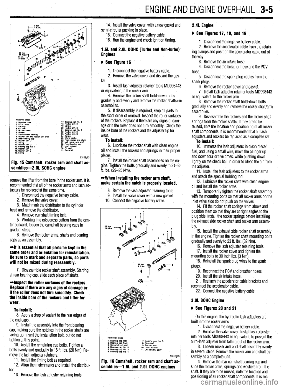
ENGINEANDENGINEOVERHALJL 3-5
Fig. 15 Camshaft, rocker arm and shaft as-
remblies-2.01 SOHC engine
remove the lifter from the bore in the rocker arm. It is
recommended that all of the rocker arms and lash ad-
justers be replaced at the same time.
1. Disconnect the negative battery cable.
2. Remove the valve cover.
3. Matchmark the distributor to the cylinder
head and remove the distributor.
4. Remove camshaft timing belt.
5. Working in a crisscross pattern from the cen-
ter outward, loosen the camshaft bearing caps in
gradual steps.
6. Remove the rocker arms, shafts and bearing
caps as an assembly.
*It is essential that all parts be kept in the
same order and orientation for reinstallation.
Be sure to mark and separate parts, so parts
will not be mixed during reassembly.
7. Disassemble rocker shaft assembly. Starting
at rear bearing cap, slide each piece off shafts.
*Inspect the roller surfaces of the rockers.
Replace if there are any signs of damage or
if the roller does not turn smoothly. Check
the inside bore of the rockers and lifter for
wear.
To install:
8. Apply a drop of sealant to the rear edges of
the end caps.
9. Install the assembly into the front bearing
cap, making sure the notches in the rocker shafts are
facing up. Insert the installation bolt, but do not
tighten at this point.
10. Install the remaining cap bolts. Tighten all
bolts evenly and gradually to 15 ft. Ibs. (20 Nm). Re-
move the lash adjuster retainers.
11. Install the timing belt as required.
12. Align the matchmarks and install the distribu-
tor.
13. Remove the lash adjuster retaining tools. 14. Install the valve cover, with a new gasket and
semi-circular packing in place.
15. Connect the negative battery cable.
16. Run the engine and check ignition timing.
1.6L and 2.OL DOHC (Turbo and Non-turbo)
Engines
6 See Figure 16
1. Disconnect the negative battery cable.
2. Remove the valve cover and discard the gas-
ket.
3. Install lash adjuster retainer tools MD998443
or equivalent, to the rocker arm.
4. Remove the rocker shaft hold-down bolts
gradually and evenly and remove the rocker shaft/arm
assemblies.
5. If disassembly is required, keep all parts in
the exact order of removal. Inspect the roller surfaces
of the rockers. Replace if there are any signs of dam-
age or if the roller does not turn smoothly. Check the
inside bore of the rockers and the adjuster tip for
wear.
To install: 6. Lubricate the rocker shaft with clean engine
oil and install the rockers and springs in their proper
places.
7. Install the rocker shaft assemblies on the en-
gine. Tighten the bolts gradually and evenly to 21-25
ft. Ibs. (29-35 Nm).
*When installing the rocker arm shaft,
make certain the notch is properly located.
8. Remove the lash adiuster retainina tools
9. Install the valve cover with a new gasket.
10. Connect the negative battery cable.
F :ig. 16 Camshaft, rocker arm and shaft as
s iemblies-1.6L and 2.OL DOHC engines
*o Nm
IILlbs -
9315390 3
2.4L Engine
# See Figures 17, 16, and 19
1. Disconnect the negative battery cable.
2. Remove the accelerator cable from the retain-
ing clamps and position the accelerator cable out of
the way.
3. Remove the air intake hose.
4. Disconnect the breather hose and the PCV
hose.
5. Disconnect the spark plug cables from the
spark plugs.
6. Remove the rocker cover and gasket.
7. Install lash adjuster retainer tools MD998443
or equivalent, to the rocker arm.
8. Remove the rocker shaft hold-down bolts
gradually and evenly and remove the rocker shaft/arm
assemblies.
9. Disassemble the rockers and the rocker shaft
springs from the rocker shafts. If they are to be
reused, note the location and positionrng of all rocker
shaft components. It is recommended that all lash
adjusters and rockers be replaced as a complete set.
To install: 10. Immerse the lash adjusters in clean diesel
fuel, and using a small wire, move the plunger up
and down four or five times. while pushing down
lightly on the check ball in order to bleed the air from
the adjuster.
11. Install the lash adjusters to the rocker arms
and attach the special holding tool.
12. Lubricate the rocker shaft with clean engine
oil and install the rocker arms.
13. Temporarily tighten the rocker shaft assembly
with the mounting bolts so that all rocker arms on the
inlet valve side do not push on the valves,
14. Fit the rocker shaft springs from above and
position them so that they are at right angles to the
plug side. Install the rocker springs before installing
the exhaust side rocker shaft and rocker arm assem-
bly.
15. Install the exhaust side rocker shaft assembly
in the engine. Tighten the rocker shaft mounting bolts
gradually and evenly to 23 ft. Ibs. (32 Nm).
16. Remove the lash adjuster retaining tools.
17. Install the rocker cover and tighten the
mounting bolts to 30 inch Ibs. (3 Nm).
18. Reinstall the spark plug wires to the spark
plugs.
19. Reconnect the PCV and breather hoses.
20. Install the air intake hose.
21. Reattach the accelerator cable brackets and
reconnect the accelerator cable.
22. Connect the negative battery cable.
3.OL SOHC Engine
6 See Figures 20 and 21
On this engine, the hydraulic lash adjusters are
built into the rocker arms,
1. Disconnect the negative battery cable.
2. Remove the valve cover. Install lash adjuster
retainer tools MD998443 or equivalent, to prevent the
auto-lash adjuster from falling out of the rocker arm.
3. Loosen rocker arm and shaft assembly evenly
in several steps. Remove the rocker arm and shaft as-
sembly as a complete unit.
4. Remove the rear camshaft bearing cap and
slide the rocker arms, springs and washers from the
shaft. If they are to be reused, note the location and
positioning of all rocker shaft components. It is rec-
Page 67 of 408
.
3-6 ENGINEANDENGINEOVERHAUL
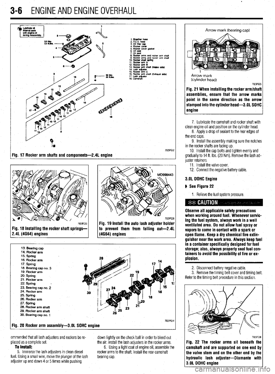
I Fig. 17 Rocker arm shafts and components-2.41 engine
Fig. 18 Installing the rocker shaft springs- 79231632
13. Bearing cap
14. Rocker arm
15. spring
16. Rocker arm
17. Spring
16 Bearing no. cap 3
IQ. Rocker arm
20. spring
21. Rocker arm
22. Spring
23. Bearing no. cap 2
24. Rocker arm
25. spring
26. Rocker arm
27. Spring
28. Rocker arm shaft
29. Rocker arm shaft
30. Bearing no. cap 1
Fig. 20 Rocker arm assembly-3.01 SOHC engine 7923PG3
ommended that all lash adjusters and rockers be re-
placed as a complete set.
To install:
5. Immerse the lash adjusters in clean diesel
fuel. Using a small wire, move the plunger of the lash
adjuster up and down 4 or 5 times while pushing down lightly on the check ball in order to bleed out
the air. Install the lash adjusters in the rocker arms.
6. Using a light coat of engine oil, assemble the
rocker arms to the shaft. Install the rear camshaft
bearing cap.
Arrow mark (bearing cap)
Arrow mark
fcyllnder head)
7923PG35 Fig. 21 When installing the rocker arm/shafi
assemblies, ensure that the arrow marks
point in the same direction as the arrow
stamped into the cylinder head-3.01 SOHC
engine
7. Lubricate the camshaft and rocker shaft with
clean engine oil and position on the cylinder head.
8. Apply a drop of sealant to the rear edges of
the end caps.
9. Install the assembly making sure the notches
in the rocker shafts are facing up.
10. Install the cap bolts and tighten evenly and
gradually to 14 ft. Ibs. (20 Nm). Remove the lash ad-
juster retainers
11. Install the valve cover.
12. Connect the negative battery cable.
3.OL OOHC Engine
) See Figure 22
1. Relieve the fuel system pressure.
Observe all applicable safety precautions
when working around fuel. Whenever servic-
ing the fuel system, always work in a well
ventilated area. 00 not allow fuel spray or
vapors to come in contact with a spark or
open flame. Keep a dty chemical fire extin-
guisher near the work area. Always keep fuel
in a container specifically designed for fuel
storage; also, always properly seal fuel con-
tainers to avoid the possibility of fire or ex-
plosion.
2. Disconnect battery negative cable.
3. Remove the timino belt cover and timina belt.
Refer to the timing belt procedure in this section.
7923PG3 Fig. 22 The rocker arms sit beneath the
camshaft and are supported on one end bl
the valve stem and on the other end by the
hydraulic lash adjuster-Oiamante wit1
3.OL OOHC engine
Page 68 of 408
ENGINEANDENGINEOVERHAUL 3-7
4. Remove the center cover, breather and PCV
hoses, and spark plug cables.
5. Remove the rocker cover.
6. Remove the throttle body stay, both camshaft
sprockets, and oil seals.
7. Remove the Camshaft Position fCMP) sensor 3. install the lash adjuster clips on the rocker
arms, then loosen the bearing cap bolts. Do not re-
move the bolts from the bearing caps.
4. Remove the rocker arms, shafts and bearing
caps as an assembly.
lo hlstall: unless it is contaminated or is several years old.
3. Remove any necessary components to access
the thermostat.
4. Remove the thermostat housinq retaininq
nd adapter from the rear of the camshah. ’
8. Remove the intake and exhaust camshafts.
9. Remove rocker arms and lash adjusters from
he head. It is recommended that all lash adjusters
md rockers be replaced as a complete set.
To Install:
10. Immerse the lash adjusters in clean diesel
uel. Using a small wire, move the plunger of the lash
tdjuster up and down four or five times while push-
ng down lightly on the check ball in order to bleed
jut the air. Lubricate and install the lash adjusters in
he cylinder head.
11. Lubricate the camshafts with clean enqine oil
nd position the camshafts on the cylinder head.
12. Install the bearing caps. Tighten the caps in
sequence, in 2 or 3 steps. Caps 2,3 and 4 have a
ront mark. Install with the mark aligned with the front
nark on the cylinder head. Intake caps have I
stamped on the cap and exhaust caps have E. Also,
)e sure the rocker arm is correctly mounted on the
ash adjuster and the valve stem end. Torque the front
md rear retaining cap bolts to 14 ft. Ibs. (20 Nm) and
ighten the center 3 retaining cap bolts to 8 ft. Ibs.
11 Nm).
13. Apply a coating of engine oil to the oil seals
md install.
14. Install the timing belt, valve cover and all re-
ated parts. Refer to the timing belt procedure in this
;ection. 5. Install the bearing caps/rocker arm assem-
blies. Tighten the bolts to 23 ft. Ibs. (31 Nm).
6. Remove the lash adjuster clips.
7. Install the rocker arm cover using a new gas-
ket.
8. Connect the negative battery cable.
REMOVAL &INSTALLATION
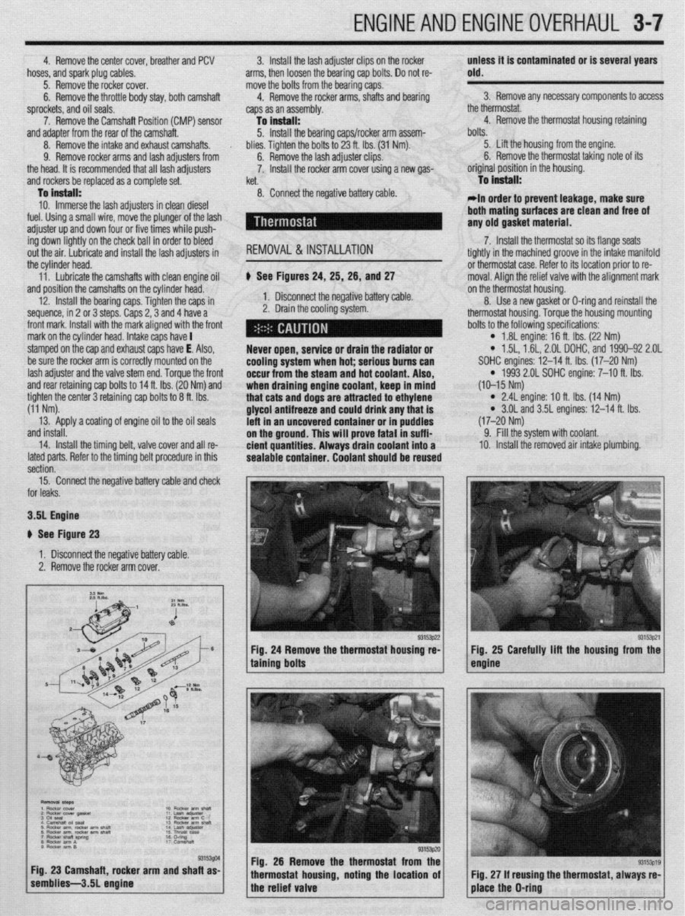
b See Figures 24, 25, 26, and 27
1. Disconnect the negative battery cable.
2. Drain the cooling system.
Never open, service or drain the radiator or
cooling system when hot; serious bums can
occur from the
steam and hot coolant. Also,
when draining engine coolant, keep in mind
that cats and dogs are attracted to ethylene
glycol antifreeze and could drink any that is
left in an uncovered container or in puddles
on the ground. This will prove fatal in suffi-
cient quantities. Always drain coolant into a
sealable container. Coolant should be reused bolts.
5. Lift the housing from the engine.
6. Remove the thermostat taking note of its
original position in the housing.
To Install:
*In order to prevent leakage, make sure
both mating
surfaces are clean and free of
any old gasket material.
7. Install the thermostat so its flange seats
tightly in the machined groove in the intake manifold
or thermostat case. Refer to its location prior to re-
moval. Aliqn the relief valve with the alignment mark
on the thermostat housing.
8. Use a new gasket or D-ring and reinstall the
thermostat housing. Torque the housing mounting
bolts to the following specifications:
l 1.8L engine: 16 ft. Ibs. (22 Nm) l 1.5L, 1.61, 2.OL DOHC, and 1990-92 2.OL
SOHC engines: 12-14 ft. Ibs. (17-20 Nm)
l 1993 2.01 SOHC engine: 7-10 ft. Ibs.
(10-15 Nm)
l 2.4L engine: IO ft. Ibs. (14 Nm) l 3.OL and 3.5L engines: 12-14 ft. Ibs.
(17-20 Nm)
9. Fill the system with coolant.
10. Install the removed air intake plumbing.
15. Connect the negative battery cable and check
or leaks.
3.51 Engine
I See Figure 23
1. Disconnect the negative battery cable.
2. Remove the rocker arm cover.
g. 26 Remove the thermostat from the
ousing, noting the location of using the thermostat, always re-