1900 MITSUBISHI DIAMANTE relay
[x] Cancel search: relayPage 173 of 408
.
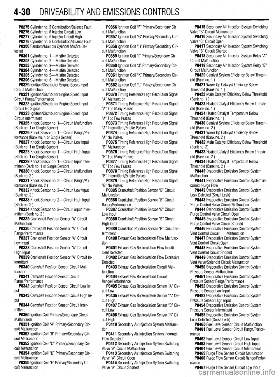
4-30 DRIVEABILITYAND EMISSIONS CONTROLS
PO275 Cvlinder no. 5 Contribution/Balance Fault
PO276 Cylinder no. 6 Injector Circuit Low
PO277 Cylinder no. 6 lniector Circuit High
PO278 Cylinder no. 6 Contribution/Balance Fault
PO300 Random/Multiple Cylinder Misfire De-
tected
PO301 Cylinder no. l-Misfire Detected
PO302 Cvlinder no 2-Misfire Detected
PO303 Cylinder no. 3-Misfire Detected
PO304 Cylinder no. 4-Misfire Detected
PO305 Cylinder no. +-Misfire Detected
PO306 Cylinder no. &-Misfire Detected
PO320 Ignition/Distributor Engine Speed Input
Circuit Malfunction
PO321 Ignition/Distributor Engine Speed Input
Circuit Range/Performance
PO322 Ignibon/Distributor Engine Speed Input
Circuit No Signal
PO323 Ignition/Distributor Engine Speed Input
Circuit Intermittent
PO325 Knock Sensor no. l-Circuit Malfunction
(Bank no. 1 or Single Sensor)
PO326 Knock Sensor no. l-Circuit Range/Per-
formance (Bank no. 1 or Srngle Sensor)
PO327 Knock Sensor no. l-Circuit Low Input
(Bank no. 1 or Single Sensor)
PO328 Knock Sensor no. l-Circuit High Input
(Bank no. 1 or Single Sensor)
PO329 Knock Sensor no. l-Circuit Input Inter-
mittent (Bank no. 1 or Smgle Sensor)
PO330 Knock Sensor no. 2-Circuit Malfunction
(Bank no. 2 )
PO331 Knock Sensor no. 2-Circuit Range/Per-
formance (Bank no. 2 )
PO332 Knock Sensor no. 2-Circuit Low Input
(Bank no. 2 )
PO333 Knock Sensor no. 2-Circuit High Input
(Bank no. 2 )
PO334 Knock Sensor no. 2-Circuit Input Inter-
mittent (Bank no. 2)
PO335 Crankshaft Position Sensor “A” Circuit
Malfunction
PO336 Crankshaft Position Sensor “A” Circuit
Range/Performance
PO337 Crankshaft Position Sensor “A” Circuit
Low Input
PO338 Crankshaft Position Sensor “A” Circuit
High Input
PO339 Crankshaft Position Sensor “A” Circuit In-
termittent
PO340 Camshaft Position Sensor Circuit Mal-
function
PO341 Camshaft Position Sensor Circuit
Range/Performance
PO342 Camshaft Position Sensor Circuit Low In-
put
PO343 Camshaft Position Sensor Circuit High In-
put
PO344 Camshaft Position Sensor Circuit Inter-
mittent
PO350 Ignition Coil Primary/Secondary Circuit
Malfunction
PO351 Ignition Coil “A” Primary/Secondary Cir-
cuit Malfunction
PO352 Ignition Coil “B” Primary/Secondary Cir-
cuit Malfunction
PO353 Ignition Coil “C” Primary/Secondary Cir-
cuit Malfunction
PO354 Ignition Coil “D” Primary/Secondary Cir-
cuit Malfunction
PO355 Ignition Coil “E” Primary/Secondary Cir-
cuit Malfunction PO356 Ignition Coil “F” Primary/Secondary Cir-
cuit Malfunction
PO357 Ignition Coil “G” Primary/Secondary Cir-
cuit Malfunction
PO358 Ignition Coil ‘Y-l” Primary/Secondary Cir-
cuit Malfunctron
PO359 Ignition Coil “I” Primary/Secondary Cir-
cuit Malfunction
PO360 Ignition Coil “J” Primary/Secondary Cir-
cuit Malfunction
PO361 Ignition Coil “K” Primary/Secondary Cir-
cuit Malfunction
PO362 Ignition Coil “L” Primary/Secondary Cir-
cuit Malfunction
PO370 Timing Reference High Resolution Signal
“A” Malfunction
PO371 Timing Reference High Resolution Signal
“A” Too Many Pulses
PO372 Timing Reference High Resolution Signal
“A” Too Few Pulses
PO373 Timing Reference High Resolution Signal
“A” Intermittent/Erratic Pulses
PO374 Timing Reference High Resolution Signal
“A” No Pulses
PO375 Timing Reference High Resolution Signal
“B” Malfunction
PO376 Timing Reference High Resolution Signal
“B” Too Many Pulses
PO377 Timing Reference High Resolution Signal
9” Too Few Pulses
PO378 Timing Reference High Resolution Signal
“B” Intermittent/Erratic Pulses
PO379 Timing Reference High Resolution Signal
“B” No Pulses
PO385 Crankshaft Position Sensor 9” Circuit
Malfunction
PO386 Crankshaft Position Sensor “B” Circuit
Range/Performance
PO387 Crankshaft Position Sensor ‘9” Circuit
Low Input
PO388 Crankshaft Position Sensor “B” Circuit
High Input
PO389 Crankshaft Position Sensor “B” Circuit In-
termittent
PO400 Exhaust Gas Recirculation Flow Malfunc-
tion
PO401 Exhaust Gas Recirculation Flow Insuffi-
cient Detected
PO402 Exhaust Gas Recirculation Flow Excessive
Detected
PO403 Exhaust Gas Recirculation Circuit Mal-
function
PO404 Exhaust Gas Recirculation Circuit
Range/Performance
PO405 Exhaust Gas Recirculation Sensor “A” Cir-
cuit Low
PO406 Exhaust Gas Recirculation Sensor “A” Cir-
cuit High
PO407 Exhaust Gas Recirculation Sensor “B” Cir-
cuit Low
PO408 Exhaust Gas Recirculation Sensor “B” Cir-
cuit High
PO410 Secondary Air Injection System Malfunc-
tion
PO411 Secondary Air Injection System Incorrect
Flow Detected
PO412 Secondary Air Injection System Switching
Valve “A” Circuit Malfunction
PO413 Secondary Air Injection System Switching
Valve “A” Circuit Open
PO414 Secondary Air Injection System Switching
Valve “A” Circuit Shorted PO415 Secondary Air Injection System Switching
Valve “B” Circuit Malfunction
PO416 Secondary Air Injection System Switching
Valve “B” Circuit Open
PO417 Secondary Air Injection System Switching
Valve “B” Circuit Shorted
PO418 Secondary Air Injection System Relay “A
Circuit Malfunction
PO419 Secondary Air Injection System Relay “B”
Circuit Malfunction
PO420 Catalyst System Efficiency Below Thresh-
old (Bank no. 1 )
PO421 Warm Up Catalyst Efficiency Below
Threshold (Bank no. 1 )
PO422 Main Catalyst Efficiency Below Threshold
(Bank no. 1 )
PO423 Heated Catalyst Efficiency Below Thresh-
old (Bank no. 1 )
PO424 Heated Catalyst Temperature Below
Threshold (Bank no. 1)
PO430 Catalyst System Efficiency Below Thresh-
old (Bank no. 2 )
PO431 Warm Up Catalyst Efficiency Below
Threshold (Bank no. 2 )
PO432 Main Catalyst Efficiency Below Threshold
(Bank no. 2)
PO433 Heated Catalyst Efficiency Below Thresh-
old (Bank no. 2 )
PO434 Heated Catalvst Temoerature Below
Threshold (Bank no. 2
j ’
PO440 Evaporative Emission Control System
Malfunction
PO441 Evaporative Emission Control System In-
correct Purge Flow
PO442 Evaporative Emission Control System
Leak Detected (Small Leak)
PO443 Evaporative Emission Control System
Purge Control Valve Circuit Malfunction
PO444 Evaporative Emission Control System
Purge Control Valve Circuit Open
PO445 Evaporative Emission Control System
Purge Control Valve Circuit Shorted
PO446 Evaporative Emission Control System
Vent Control Circuit Malfunction
PO447 Evaporative Emission Control System
Vent Control Circuit Open
PO448 Evaporative Emission Control System
Vent Control Circuit Shorted
PO449 Evaporative Emission Control System
Vent Valve/Solenoid Circuit Malfunction
PO450 Evaporative Emission Control System
Pressure Sensor Malfunction
PO451 Evaporative Emission Control System
Pressure Sensor Range/Performance
PO452 Evaporative Emission Control System
Pressure Sensor Low Input
PO453 Evaporative Emission Control System
Pressure Sensor High Input
PO454 Evaporative Emission Control System
Pressure Sensor Intermittent
PO455 Evaporative Emission Control System
Leak Detected (Gross Leak)
PO460 Fuel Level Sensor Circuit Malfunction
PO461 Fuel Level Sensor Circuit Range/Perfor-
mance
PO462 Fuel Level Sensor Circuit Low Input
PO463 Fuel Level Sensor Circuit High Input
PO464 Fuel Level Sensor Circuit Intermittent
PO465 Purge Flow Sensor Circuit Malfunction
PO466 Purge Flow Sensor Circuit Range/Perfor-
mance
PO467 Purge Flow Sensor Circuit Low Input
Page 175 of 408
4-32 DRIVEABILITYAND EMISSIONS CONTROLS
PO785 Shift/Timing Solenoid Malfunction
PO786 Shift/Timing Solenoid Range/Performance
PO787 Shift/Timing Solenoid Low
PO788 Shift/Timing Solenord High
PO789 Shift/Timing Solenoid Intermittent
PO790 Normal/Performance Switch Circuit Mal-
function
PO801 Reverse Inhibit Control Circuit Malfunc-
tion
PO803 l-4 Upshift (Skip Shift) Solenoid Control
Circuit Malfunction
PO804 l-4 Upshift (Skip Shift) Lamp Control
Circuit Malfunction
PllOO Induction Control Motor Position Sensor
Fault
PI101 Traction Control Vacuum Solenoid Circuit
Fault
Pl102 Traction Control Ventilation Solenoid Cir-
cuit Fault P1294 Target Idle Speed Not Reached
P1295 No 5-Volt Supply To TP Sensor
P1296 No 5-Volt Supply To MAP Sensor
P1297 No Change In MAP From Start To Run
PI300 Ignition Timing Adjustment Circuit
Pl390 Timing Belt Skipped One Tooth Or More
Pl391 Intermittent Loss Of CMP Or CKP Sensor
Signals P1495 EVAP Ventilation Solenoid Circurt Fault
P1496 5-Volt Supply Output Too Low
Pl500 Generator FR Terminal Circuit Fault
Pl600 PCM-TCM Serial Communication Link
Circuit Fault
Pl400 Manifold Differential Pressure Sensor
Fault P1696 PCM Failure- EEPROM Write Denied
Pl715 No CCD Messages From TCM
Pl750 TCM Pulse Generator Circuit Fault
Pl791 Pressure Control, Shift Control, TCC So-
lenoid Fault
P1443 EVAP Purge Control Solenoid “2” Circuit
Fault P1899 PCM ECT Level Signal to TCM Circuit
Fault
P1486 EVAP Leak Monitor Pinched Hose De-
tected
P1989 High Speed Condenser Fan Control Relay
Fault
P1487 High Speed Radiator Fan Control Relay
Circuit Fault
Pl490 Low Speed Fan Control Relay Fault
P1492 Battery Temperature Sensor High Voltage
P1494 EVAP Ventilation Switch Or Mechanical
FLASH OUT CODE LIST
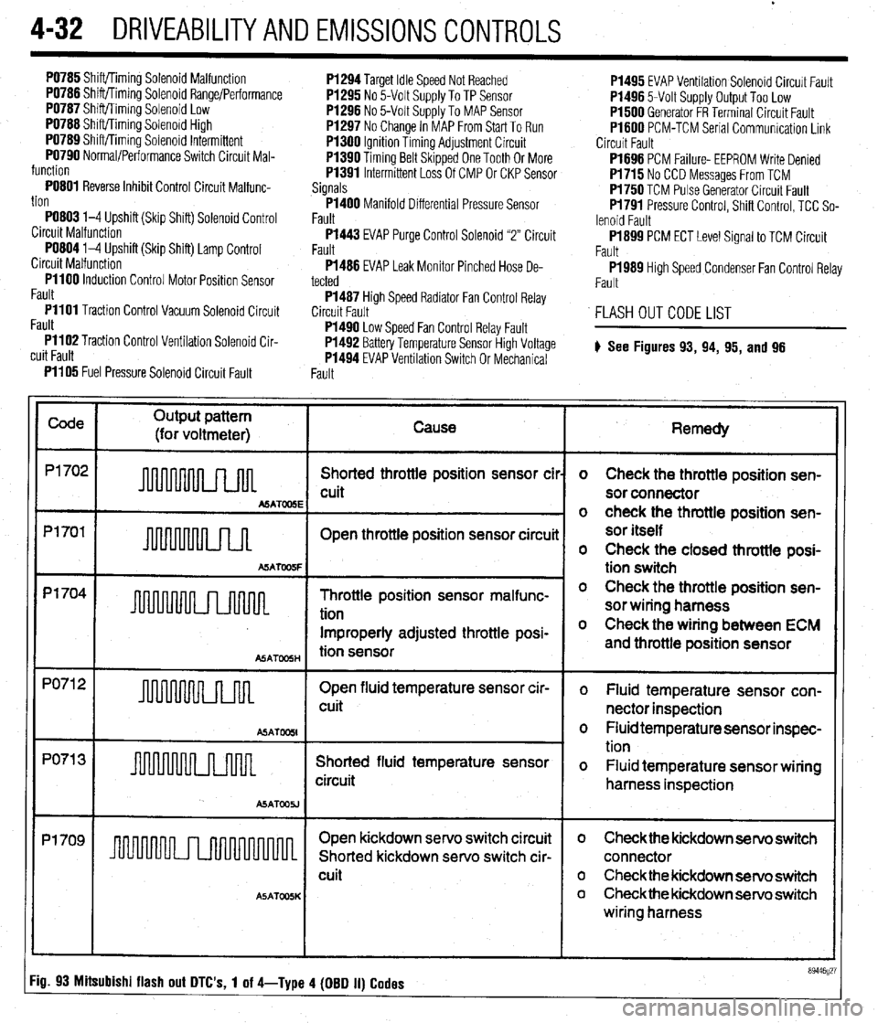
# See Figures
93, 94, 95, and 96
Fault PI105 Fuel Pressure Solenoid Circuit Fault
Code
Output pattern
(for voltmeter) Cause
P1702
Shorted throttle position sensor cil
cuit
MATOOSE
Pl701
Open throttle position sensor circuii
A!iATW5F
p1704 -
Throttle position sensor malfunc-
tion
Improperly adjusted throttle posi-
ASATmH tion sensor
PO71 2
Open fluid temperature sensor cir-
u 1 cuit
ASAT
PO71 3
Shorted fluid temperature sensor
circuit
ASATOOU
Pl709
I I Open kickdown servo switch circuit
Shorted kickdown servo switch cir-
cuit
A5ATOOSK
Remedy
o Check the throttle position sen-
sor connector
o check the throttle position sen-
sor itself
o Check the closed throttle posi-
tion switch
o Check the throttle position sen-
sor wiring harness
o Check the wiring between ECM
and throttle position sensor
o Fluid temperature sensor con-
nector inspection
o Fluid temperature sensor inspec-
tion
o Fluid temperature sensor wiring
harness inspection
o Check the kickdown servo switch
connector
o Check the kickdown servo switch
o Checkthe kickdown servo switch
wiring harness
Fig. 93 Mitsubishi flash out DTC's, 1 of 4-Type 4 (DBD II) Codes
Page 204 of 408
UNDERSTANDING AND
TROUBLESHOOTING
ELECTRICAL SYSTEMS 6-2
BASIC ELECTRICALTHEORY 6-2
HOW DOES ELECTRICITY WORK:
THEWATERANALOGY 6-2
OHM'S LAW 6-2
ELECTRICALCOMPONENTS 6-2
POWERSOURCE 6-2
GROUND 6-3
PROTECTIVE DEVICES 6-3
SWITCHES&RELAYS 6-3
LOAD 6-3
WIRING & HARNESSES 6-3
CONNECTORS 6-4
TEST EQUIPMENT 6-4
JUMPER WIRES 6-4
TEST LIGHTS 6-4
MULTIMETERS 6-5
TROUBLESHOOTING ELECTRICAL
SYSTEMS 6-5
TESTING 6-5
OPEN CIRCUITS 6-5
SHORT CIRCUITS 6-6
VOLTAGE 6-6
VOLTAGE DROP 6-6
RESISTANCE 6-8
WIRE AND CONNECTORREPAIR 6-6
BATTERY CABLES 6-7
DISCONNECTING THE CABLES 6-7
AIR BAG (SUPPLEMENTAL
RESTRAINT SYSTEM) 6-7
GENERALINFORMATION 6-7
SERVICE PRECAUTIONS 6-7
DISARMING 6-7
REARMING 6-7
HEATING AND AIR
CONDITIONING 6-7
BLOWER MOTOR 6-7
REMOVAL &INSTALLATION 6-7
HEATER CORE 6-9 INSTRUMENTS AND SWITCHES 6-17
INSTRUMENTCLUSTER 6-17
REMOVAL &INSTALLATION 6-17
GAUGES 6-18
REMOVAL&INSTALLATION 6-18
WINDSHIELD WIPER SWITCH 6-19
REMOVAL&INSTALLATION 6-19
REARWINDOWWIPERSWITCH 6-19
REMOVAL &INSTALLATION 6-19
DIMMER SWITCH 6-19
REMOVAL & INSTALLATION 6-19 .
HEADLIGHT SWITCH 6-19
REMOVAL & INSTALLATION 6-19
LIGHTING 6-19
HEADLIGHTS 6-19
REMOVAL &INSTALLATION 6-19
AIMINGTHEHEADLIGHTS 6-20
SIGNAL AND MARKER LIGHTS 6-21
REMOVAL &INSTALLATION 6-21
CIRCUIT PROTECTION 6-27
FUSES 6-27
REPLACEMENT 6-27
FUSIBLE LINKS 6-27
CIRCUIT BREAKERS 6-28
RESETTING AND/OR
REPLACEMENT 6-28
FLASHERS 6-28
REPLACEMENT 6-28
WIRING DIAGRAMS 6-31
REMOVAL & INSTALLATION 6-9
AIR CONDITIONING COMPONENTS 6-11
REMOVAL & INSTALLATION 6-11
CONTROLCABLES 6-12
ADJUSTMENT 6-12
CONTROL PANEL 6-12
REMOVAL & INSTALLATION 6-12
CRUISE CONTROL 6-13
ENTERTAINMENT SYSTEMS 6-14
RADIO RECEIVER/AMPLIFIER/TAPE
PLAYER/CD PLAYER 6-14
SPEAKERS 6-14
REMOVAL & INSTALLATION 6-14
WINDSHIELD WIPERS AND
WASHERS 6-15
WINDSHIELD WIPER BLADE AND
ARM 6-15
REMOVAL & INSTALLATION 6-15
WINDSHIELD WIPER MOTOR 6-16 _
REMOVAL &INSTALLATION 6-16
WINDSHIELD WASHER PUMP 6-17
REMOVAL &INSTALLATION 6-17
Page 205 of 408
6-2 CHASSIS ELECTRICAL
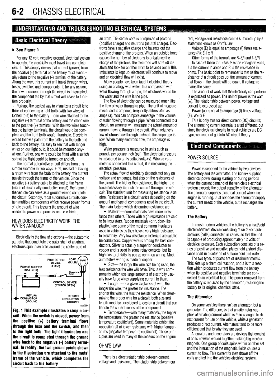
) See Figure 1
For any 12 volt, negative ground, electrical system
to operate, the electricity must travel in a complete
circurt. This simply means that current (power) from
the posibve (t) terminal of the battery must eventu-
ally return to the negative (-) terminal of the battery.
Along the way, this current will travel through wires,
fuses, switches and components. If, for any reason,
the flow of current through the circuit is interrupted,
the component fed by that circuit will cease to func-
tion properly.
Perhaps the easiest way to visualize a circuit is to
think of connecting a light bulb (with two wires at-
tached to it) to the battery-one wire attached to the
negative (-) terminal of the battery and the other wire
to the positive (t) terminal. With the two wires touch-
ing the battery terminals, the circuit would be com-
plete and the light bulb would illummate. Electricity
would follow a path from the battery to the bulb and
back to the battery. It’s easy to see that wrth longer
wires on our light bulb, it could be mounted any-
where. Further, one wire could be fitted with a switch
so that the light could be turned on and off.
The normal automotive circuit differs from this
simple example in two ways, Frrst, instead of having
a return wire from the bulb to the battery, the current
travels through the frame of the vehicle. Since the
negative (-) battery cable is attached to the frame
(made of electrically conductive metal), the frame of
the vehicle can serve as a ground wire to complete
the circuit. Secondly, most automotive circuits con-
tain multiple components which receive power from a
single circuit. This lessens the amount of wire
needed to power components on the vehicle.
HOW DOES ELECTRlClTYWORK:THE
WATER ANALOGY
Electricity is the flow of electrons-the subatomic
particles that constitute the outer shell of an atom.
Electrons spin in an orbit around the center core of
RETURN
RETURN
CONDUCTOR
CONDUCTOR
GROUND
GROUND
lccs2w
Fig. 1 This example illustrates a simple cir-
cuit. When the switch is closed, power from
the positive (t) battery terminal flows
through the fuse and the switch, and then
to the light bulb. The light illuminates and
the circuit is completed through the ground
wire back to the negative (-) battery termi-
nal. In reality, the two ground points shown
in the illustration are attached to the metal
frame of the vehicle, which completes the
circuit back to the battery
an atom The center core is comprised of protons
(positive charge) and neutrons (neutral charge). Elec-
trons have a negative charge and balance
out the
positive charge of the protons. When an outside force
causes the number of electrons to unbalance the
charge of the protons, the electrons will split off the
atom and look for another atom to balance out. If this
imbalance is kept up, electrons will continue to move
and an electrical flow will exist.
Many people have been taught electrical theory
using an analogy with water. In a comparison wrth
water flowing through a pipe, the electrons would be
the water and the wire is the pipe.
The flow of electricity can be measured much like
the flow of water through a pipe. The unit of measure-
ment used is amperes, frequently abbreviated as
amps (a). You can compare amperage to the volume
of water flowing through a pipe. When connected to a
circuit, an ammeter WIII measure the actual amount of
current flowing through the circuit. When relatively
few electrons flow through a circuit, the amperage is
low. When many electrons flow, the amperage is
high.
Water pressure is measured in units such as
pounds per square inch (psi); The electrical pressure
is measured in unrts called volts (v). When a volt-
meter is connected to a circuit, it is measuring the
electrical pressure.
The actual flow of electricity depends not only on
voltage and amperage, but also on the resistance of
the circuit The higher the resistance, the higher the
force necessary to push the current through the cir-
cuit. The standard unit for measuring resistance is an
ohm. Resistance in a crrcuit varies dependmg on the
amount and type of components used in the circuit.
The main factors which determine resistance are:
l Material-some materials have more resis-
tance than others Those with high resistance are said
to be insulators Rubber materials (or rubber-like
plashcs) are some of the most common insulators
used in vehicles as they have a very high resistance
to electricity Very low resistance materials are said to
be conductors. Copper wire is among the best con-
ductors. Silver is actually a superior conductor to
copper and is used in some relay contacts, but its
high cost prohibits its use as common wiring Most
automotive wiring is made of copper.
l Size-the larger the wire size being used, the
less resistance the wire will have. This IS why com-
ponents which use large amounts of electricity usu-
ally have large wires supplying current to them.
l Length-for a given thickness of wire, the
longer the wire, the greater the resistance. The
shorter the wire, the less the resistance. When deter-
mining the proper wire for a circuit, both size and
length must be considered to design a circuit that can
handle the current needs of the component.
l Temperature-with many materials, the higher
the temperature, the greater the resistance (positive
temperature coefficient). Some materials exhibit the
opposite trait of lower resistance with higher temper-
atures (negative temperature coefficient). These prin-
ciples are used in many of the sensors on the engine
OHM'S LAW
There is a direct relationship between current,
voltage and resistance. The relationship between cur- rent, voltage and resistance can be summed up by a
statement known as Ohm’s law.
Voltage (E) is equal to amperage (I) times resis-
tance (R): E=l x R
Other forms of the formula are R=E/I and I=E/R
In each of these formulas, E is the voltage in volts,
I is the current in amps and R IS the resistance in
ohms. The basic point to remember is that as the re-
sistance of a circuit goes up, the amount of current
that flows in the circuit will go down, if voltage re-
mains the same.
The amount of work that the electricity can perform
is expressed as power. The unit of power is the watt
(w). The relationship between power, voltage and
current
IS expressed as:
Power(w) is equal to amperage (I) times voltage
(E): W=l x E
This is only true for direct current (DC) circuits:
The alternating current formula is a tad different, but
since the electrical circuits in most vehicles are DC
type, we need not get into AC circuit theory.
POWERSOURCE
Power is supplied to the vehicle by two devices:
The battery and the alternator. The battery supplies
electrical power during starting or during periods
when the current demand of the vehicle’s electrical
system exceeds the output capacity of the alternator.
The alternator supplies electrical current when the
engine is running
Just not does the alternator supply
the current needs of the vehicle, but it recharges the
battery.
The Battery
In most modern vehicles, the battery is a lead/acid
electrochemical device consisting of six 2 volt sub-
sections (cells) connected in series, so that the unit
is capable of producing approximately 12 volts of
electrical pressure. Each subsection consists of a se-
ries of positive and negative plates held a short dis-
tance apart in a solutron of sulfuric acid and water.
The two types of plates are of dissimilar metals,
This sets up a chemrcal reaction, and it is this reac-
tion which produces current flow from the battery
when Its positive and negattve terminals are con-
nected to an electrical load. The power removed from
the battery is replaced by the alternator, restoring the
battery to its original chemical state.
The Alternator
On some vehicles there isn’t an alternator, but a
generator. The difference IS that an alternator sup-
plies alternating current which is then changed to di-
rect current for
use on the vehicle, while a generator
produces direct current. Alternators tend to be more
efficient and that is why they are used.
Alternators and generators are devices that consist
of coils of wires wound together making big electro-
magnets. One group of coils spins within another set
and the interaction of the magnetic fields causes a
current to flow. This current is then drawn off the
coils and fed into the vehicles electrical system.
Page 206 of 408
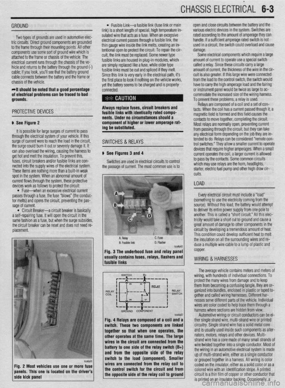
CHASSIS ELECTRliAL 6-3
SWITCH
&--; r-- ----
-~~ 85 M
I
-M-L RELAY
SWITCH 86 87
i
---
----w-J
tcca6go2 Fig. 4 Relays are composed of a coil and a
switch. These two components are linked
together so that when one operates, the
other operates at the same time. The large
wires in the circuit are connected from the
battery to one side of the relay switch (B+)
and from the opposite side of the relay
switch to the load (component). Smaller
wires are connected from the relay coil to
the control switch for the circuit and from
the opposite side of the relay coil to ground
The average vehicle contains meters and meters of
wiring, with hundreds of individual connections. To
protect the many wires from damage and to keep
them from becoming a confusing tangle, they are or-
ganized into bundles, enclosed in plastic or taped to-
gether and called wiring harnesses. Different har-
nesses serve different parts of the vehicle. Individual
wires are color coded to help trace them through a
harness where sections are hidden from view.
Automotive wiring or circuit conductors can be ei-
ther single strand wire, multi-strand wire or printed
circuitry. Single strand wire has a solid metal core
and is usually used inside such components as alter-
nators, motors, relays and other devices. Multi-
strand wire has a core made of many small strands of
wire twisted together into a single conductor. Most of
the wiring in an automotive electrical system is made
up of multi-strand wire, either as a single conductor
or grouped together in a harness. All wiring is color
coded on the insulator,,either as a solid color or as a
colored wire with an identification stripe. A printed
circuit is a thin film of copper or other conductor that
is printed on an insulator backing. Occasionally, a
Page 211 of 408
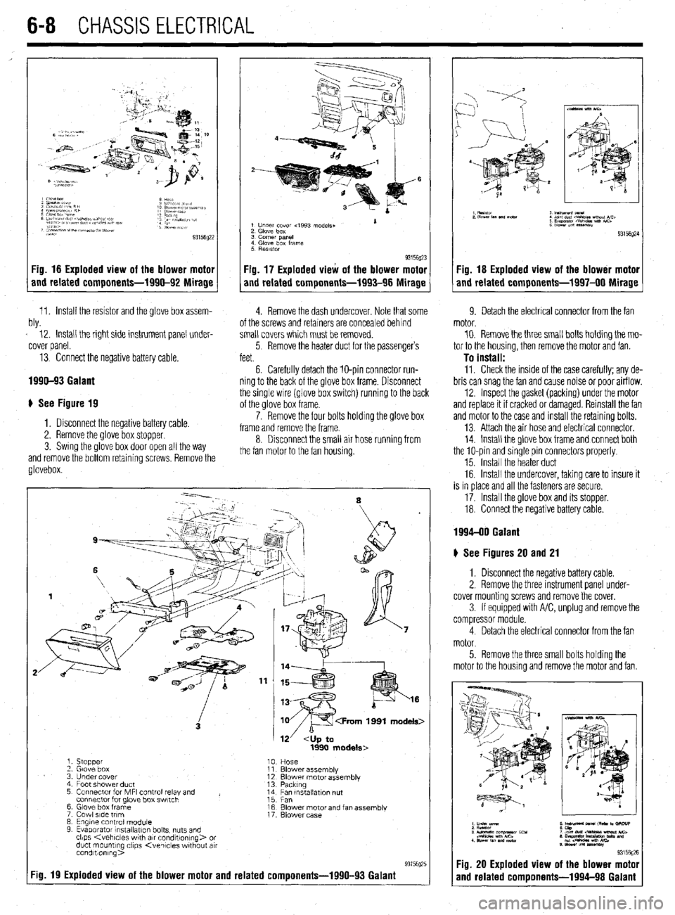
6-8 CHASSIS ELECTRICAL
Fig. 16 Exploded view of the blower motor
and related components-1990-92 Mirage
11. Install the resistor and the glove box assem- W 12. Install the right side instrument panel under-
cover panel.
13. Connect the negative battery cable.
1990-93 Galant
# See Figure 19
1. Disconnect the negative battery cable.
2. Remove the glove box stopper.
3. Swing the glove box door open all the way
and remove the bottom retainina screws. Remove the
glovebox
1 Under cover 4993 models, 1
2 Glove box
3 corner pane,
4 Glove box frame
5 RBSlStOr
93156~23
Fig. 17 Exploded view of the blower motor
and related components-1993-96 Mirage
4. Remove the dash undercover. Note that some 9. Detach the electrical connector from the fan
ot the screws and retainers are concealed behind
small covers which must be removed.
5 Remove the heater duct for the passenger’s
feet.
6. Carefully detach the lo-pin connector run-
ning to the back of the glove box frame. Disconnect
the single wire (glove box switch) running to the back
of the glove box frame.
7. Remove the four bolts holding the glove box
frame and remove the frame.
8. Disconnect the small air hose running from
the fan motor to the fan housing. motor.
10. Remove the three small bolts holding the mo-
tor to the housing, then remove the motor and fan.
To install: 11. Check the inside of the case carefully: any de-
bris can snag the fan and cause noise or poor airflow.
12. Inspect the gasket (packing) under the motor
and replace it if cracked or damaged. Reinstall the fan
and motor to the case and Install the retaining bolts.
13. Attach the air hose and electrical connector.
14. Install the glove box frame and connect both
the lo-pin and sinqle pin connectors properly.
15. Install the heater duct
16. Install the undercover, taking care to insure it
is in place and all the fasteners are secure.
17. Install the glove box and its stopper.
18. Connect the negative battery cable.
:ig. 19 Exploded view of the blower motor and related components-1990-93 Galant
1. stopper
‘2 Glove box
3 Under cover
4 Foot shower duct
5 Connector for MFI control relay and ,
connector for glove box swtch
6 Glove box frame
7 Cowl side trim
8 Engine control module
9 Evaporator lnstallatlon bolts, nuts and
clips
duct mounting clips Kvehlcles wthout air
condltionlng>
Fig. 18 Exploded view of the blower motor
and related components-1997-00 Mirage
--.
8
12’
Blower assemblv
Blower motor assembly
Packtng
;;c, tnstallatlon nut
Blower motor and fan assembly
Blower case
1994-00 Galant
) See Figures 20 and 21
1. Disconnect the negative battery cable.
2. Remove the three instrument panel under-
cover mounting screws and remove the cover.
3 If equipped with A/C, unplug and remove the
compressor module.
4. Detach the electrical connector from the fan
motor.
5. Remove the three small bolts holding the
motor to the housing and remove the motor and fan.
; y&M 5 m- M ,RC m .3RcuP
3 lulomafs corn-r ECU :2%brtr-Mbi&C>
.“eM *nn mi
1 slmhn.m”m,n 8 ~y~tipJ*-m-=%9 md
S sa*n”nlUSW
931561
Fig. 20 Exploded view of the blower mote
and related comoonents-1994-98 Galan
Page 212 of 408
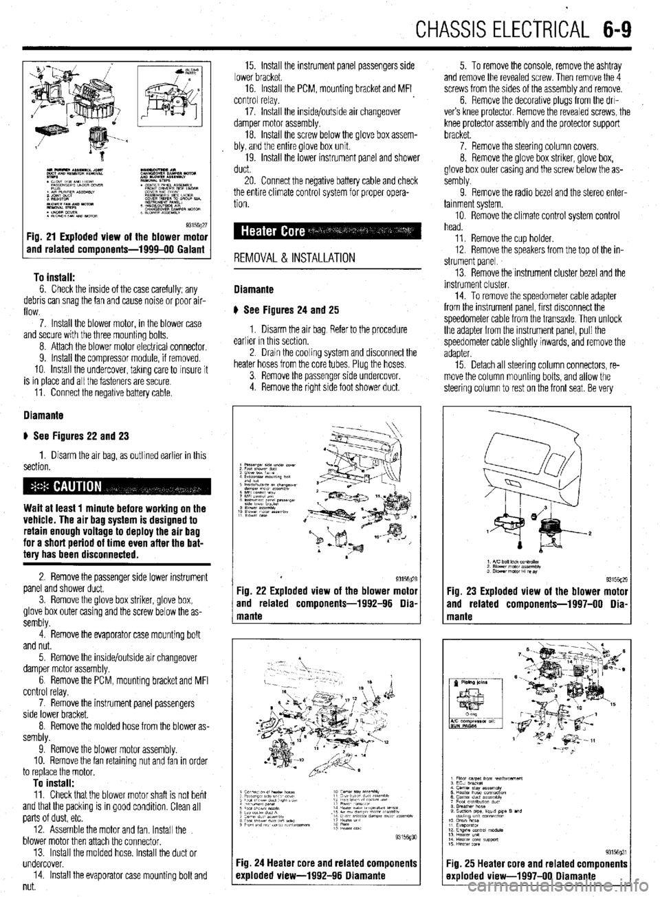
CHASSIS ELECtRldAL 6-9
93156g27 Fig. 21 Exploded view of the blower motor
and related components-1999-00 Galant
To install:
6. Check the inside of the case carefully; any
debris can snag the fan and cause noise or poor air-
flow.
7. Install the blower motor, in the blower case
and secure with the three mounting bolts,
8. Attach the blower motor electrlcal connector,
9. Install the compressor module, if removed.
10. Install the undercover, takmg care to insure it
is in place and all the fasteners are secure.
11. Connect the negative battery cable.
Diamante
u See Figures 22 and 23
1. Disarm the air bag, as outlined earlier in this
section.
Wait at least 1 minute before working on the
vehicle. The air bag system is designed to
retain enough voltage to deploy the air bag
for a short period of time even after the bat-
tery has been disconnected.
2. Remove the passenger side lower instrument
panel and shower duct,
3. Remove the glove box striker, glove box,
glove box outer casing and the screw below the as-
sembly.
4. Remove the evaporator case mounting bolt
and nut.
5. Remove the inside/outside air changeover
damper motor assembly.
6 Remove the PCM, mounting bracket and MFI
control relay.
7. Remove the instrument panel passengers
side lower bracket.
8. Remove the molded hose from the blower as-
sembly.
9. Remove the blower motor assembly.
10. Remove the fan retaining nut and fan in order
to replace the motor,
To install: 11. Check that the blower motor shaft is not bent
and that the packing is in good condition, Clean all
parts of dust, etc.
12. Assemble the motor and fan. Install the
blower motor then attach the connector.
13. Install the molded hose. Install the duct or
undercover.
14. Install the evaporator case mounting bolt and
nut. 15. Install the instrument panel passengers side
lower bracket.
16. Install the PCM, mounting bracket and MFI
control relay.
17. Install the inside/outside air changeover
damper motor assembly.
18. Install the screw below the glove box assem-
bly, and the entire glove box unit.
19. Install the lower instrument panel and shower
duct.
20. Connect the negative battery cable and check
the entire climate control system for proper opera-
tion.
REMOVAL & INSTALLATION
Diamante
u See Figures 24
and 25
1. Disarm the air bag Refer to the procedure
earlier in this section.
2. Dram the cooling system and disconnect the
heater hoses from the core tubes. Plug the hoses.
3. Remove the passenger side undercover.
4. Remove the right side foot shower duct. 5. To remove the console, remove the ashtray
and remove the revealed screw. Then remove the 4
screws from the sides of the assembly and remove.
6. Remove the decorative plugs from the drl-
ver’s knee protector. Remove the revealed screws, the
knee protector assembly and the protector support
bracket.
7. Remove the steering column covers.
8. Remove the glove box striker, glove box,
glove box outer casing and the screw below the as-
sembly.
9. Remove the radio bezel and the stereo enter-
tainment system.
10. Remove the climate control system control
head.
11. Remove the cup holder.
12. Remove the speakers from the top of the in-
strument panel.
13. Remove the instrument cluster bezel and the
instrument cluster.
14. To remove the speedometer cable adapter
from the instrument panel, first disconnect the
speedometer cable from the transaxle. Then unlock
the adapter from the instrument panel, pull the
speedometer cable slightly inwards, and remove the
adapter
15. Detach all steering column connectors, re-
move the column mounting bolts, and allow the
steering column to rest on the front seat. Be very
Fig. 23 Exploded view of the blower motor
and related components-1997-00 Dia-
Fig. 25 Heater core and related components
exploded view-1997-00 Diamante
Page 230 of 408
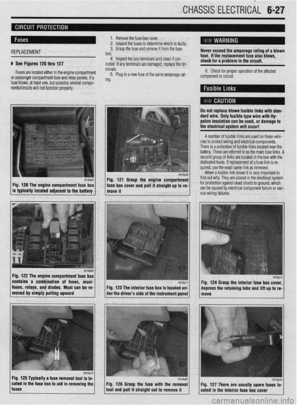
CHASSIS ELECTRICAL 6-27
1. Remove the fuse box cover.
2. lnsoect the fuses to determine which is faulty.
REPLACEMENT 3. Grasp the fuse and remove it from the fuse
box. Never exceed the amperage rating of a blown
4. Inspect the box terminals and clean if cor- fuse. If the replacement fuse also blows,
It See Figures 120 thru 127 check for a problem in the circuit.
roded. If any terminals are damaged, replace the ter-
Fuses are located either in the engine Compartment minals. ’
5. Plug in a new fuse of the same amperage rat- 6. Check for proper operation of the affected
or passenger compartment fuse and relay panels. If a component or circuit.
fuse blows, at least one, but possibly several compo- ing.
ients/circuits will not function properly.
Fig, 120 The engine compartment fuse box
is typically located adjacent to the
battery
Fig. 122 The engine compartment fuse box
contains a combination of fuses, maxi-
fuses, relays, and diodes. Most can be re-
moved by simply pulling upward
I Do not replace blown fusible links with stan-
dard wire. Only fusible type wire with Hy
palon insulation can be
used, or damage to
the electrical system will occur!
A number of fusible links are used on these vehi-
cles to protect wiring and electrical components.
There is a collection of fusible links located near the
battery. These are referred to as the main fuse links. A
second group of links are located in the box with the
dedicated fuses. If replacement of a fuse link is re-
quired, use the exact same link as removed.
When a fusible link blows it is very important to
Fig. 121 Grasp the engine compartment find out why. They are placed in the electrical system
. ’ ‘“‘,+“” 1 ous wiring failures. fuse box cover and pull It straight up to re- for protection against dead shorts to ground, which
move it can be caused by electrical component failure or vari-
Fig. 123 The interior fuse box is located un-
der the driver’s side of the instrument panel
Fig. 125 Typically a fuse removal tool is lo-
cated in the fuse box to aid in removing the
fuses Fig. 126 Grasp the fuse with the removal
tool and pull it straight out to remove it Fig. 124 Grasp the interior fuse box cover,
depress the retaining
tabs and lift up to re-