1900 MITSUBISHI DIAMANTE relay
[x] Cancel search: relayPage 273 of 408
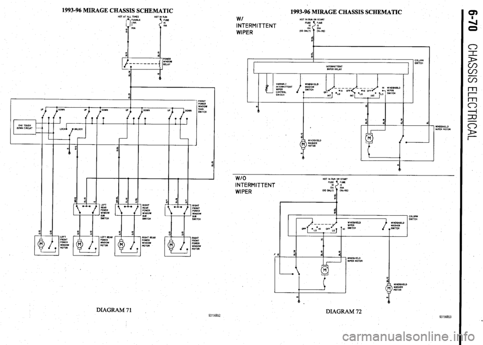
1993-96 MIRAGE CHASSIS SCHEMATIC
1993-96 MIRAGE CHASSIS SCHEMATIC
w/ HOT IN RUN OR START INTERMITTENT
WIPER
COLUMN
I-
I SWlTCH I
I INTERMITTENT
WIPER RELAY
II I I
I
VdRlABLE
INTERMITTENT
WIPER
CONTRDL
SWITCH WINDSHIELD
1 WINDSHIELD
WIPER MOTOR
WINDSHIELD
WASHER
nOTOR
r
I
1
-- LEFT
FRONT
POWER
WINDOW
NOTOR
w/o HOT IN RUN OR START INTERMITTENT
WIPER
COLUWN
SWITCH
DIAGRAM 72 93156852
93156853 DIAGRAM71
Page 278 of 408
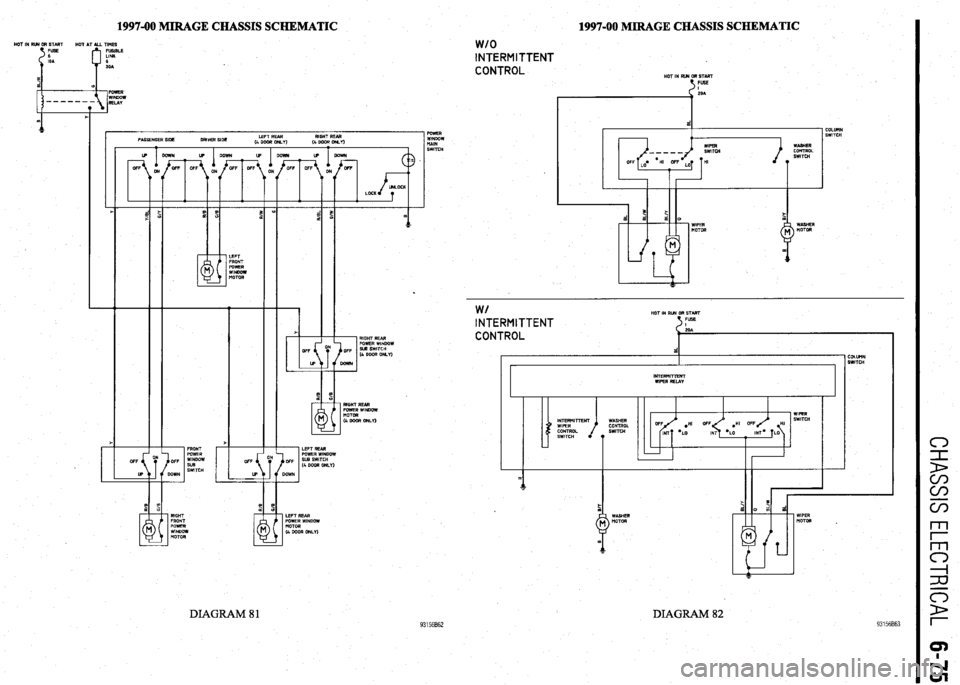
1997-00 MIRAGE CHASSIS SCHEMATIC HOT IN RR4 OR STMT
HOT AT ALL TIMES
FUSIBLE
LINK
6
SOA 1997-00 MIRAGE CHASSIS SCHEMATIC
1 POWER
WINDOW
tiAlN
SWITCH
w/o INTERMITTENT
CONTROL
HOT IN RUN OR START
t FUSE
COLUllN
SWITCH
LEFT REAR RIGHT REAR
4 DOOR or&Y)
(4WWOM.I)
I .
F ?E
d d a 0
WIPER WASHER
MOTOR MOTOR
.
93156862
W/ HOT IN RUN GR START INTERMITTENT FUSE 5
CONTROL
d COLUtlN
SWITCH
I r INTERMITTENT
WIPER RELAY
I I
WIPER
WASHER SWITCH
CONTROL .HI OFF HI
SWITCH
*LO MT= LO
T
1
LEFT REAR
POWER WINDOW
MOTOR
(4 GOOR ONLY) RIGHT
FRONT
POWER
WINDOW
MOTOR WIPER
MOTOR .
DIAGRAM 82 DIAGRAM 81
Page 341 of 408
BRAKES 9-5
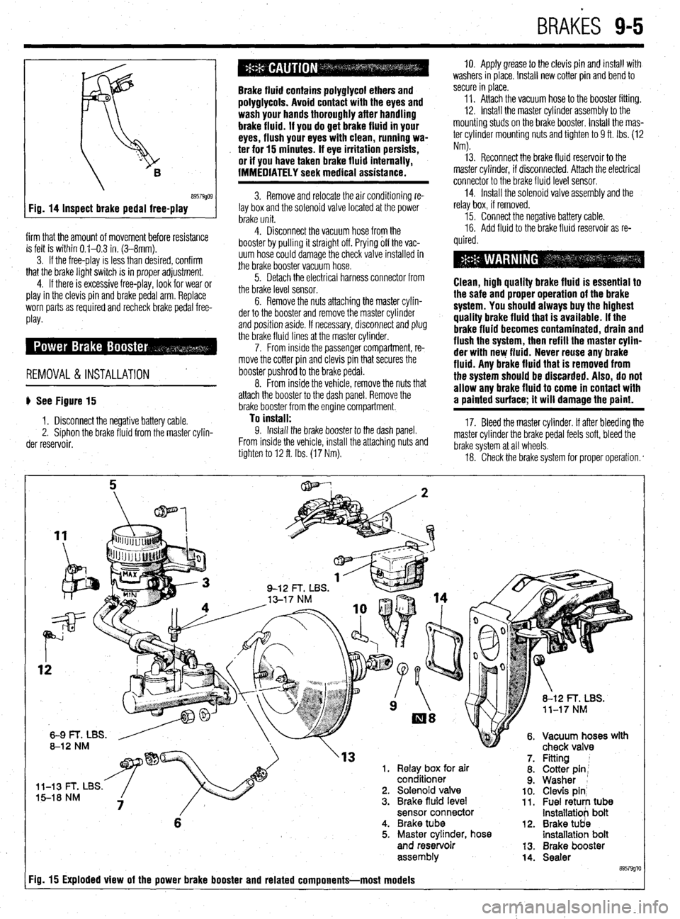
Inspect brake pedal free-play
firm that the amount of movement before resistance
is felt is within 0.1-0.3 in. (3-8mm).
3. If the free-play is less than desired, confirm
that the brake light switch is in proper adjustment.
4. If there is excessive free-play, look for wear or
play in the clevis pin and brake pedal arm. Replace
worn parts as required and recheck brake pedal free-
Play*
REMOVAL &INSTALLATION '
b See Figure 15
1. Disconnect the negative battery cable.
2. Siphon the brake fluid from the master cylin-
der reservoir.
Brake fluid contains polyglycol ethers and
polyglycols. Avoid contact with the eyes and
wash your hands thoroughly after handling
brake fluid. If you do get brake fluid in your
eyes, flush your eyes with clean, running wa-
. ter for 15 minutes. If eye irritation persists,
or if you have taken brake fluid internally,
IMMEDIATELY seek medical assistance.
3. Remove and relocate the air conditioning re-
lay box and the solenoid valve located at the power
brake unit.
4. Disconnect the vacuum hose from the
booster by pulling it straight off. Prying off the vac-
uum hose could damage the check valve installed in
the brake booster vacuum hose.
5. Detach the electrical harness connector from
the brake level sensor.
6. Remove the nuts attaching the master cylin-
der to the booster and remove the master cylinder
and position aside. If necessary, disconnect and plug
the brake fluid lines at the master cylinder.
7. From inside the passenger compartment, re-
move the cotter pin and clevis pin that secures the
booster pushrod to the brake pedal.
8. From inside the vehicle, remove the nuts that
attach the booster to the dash panel. Remove the
brake booster from the engine compartment.
To install: 9. Install the brake booster to the dash panel.
From inside the vehicle, install the attaching nuts and
tighten to 12 ft. Ibs. (17 Nm). 10. Apply grease to the clevis pin and install with
washers in place. Install new cotter pin and bend to
secure in place.
11. Attach the vacuum hose to the booster fitting.
12. Install the master cylinder assembly to the
mounting studs on the brake booster. Install the mas-
ter cylinder mounting nuts and tighten to 9 ft. Ibs. (12
Nm).
13. Reconnect the brake fluid reservoir to the
master cylinder, if disconnected. Attach the electrical
connector to the brake fluid level sensor.
14. Install the solenoid valve assembly and the
relay box, if removed.
15. Connect the negative battery cable.
16. Add fluid to the brake fluid reservoir as re-
quired.
Clean, high quality brake fluid is essentlal to
the safe and proper operation of the brake
system. You should always buy the highest
quality brake fluid that is available. If the
brake fluid becomes contaminated, drain and
flush the system, then refill the master cylin-
der with new fluid. Never reuse any brake
fluid. Any brake fluid that is removed from
the system should be discarded. Also, do not
allow any brake fluid to come in contact with
a painted surface; it will damage the paint.
17. Bleed the master cylinder. If after bleeding the
master cylinder the brake pedal feels soft, bleed the
brake system at all wheels.
18. Check the brake system for proper operation. *
rn( mr
'13 1. Relay box for air
conditioner
l-13 t- I, Ltx5. 5-18 NM 2. Solenoid valve
3. Brake fluid level
sensor connector
6 4. Brake tube
5. Master cylinder, hose
and reservoir
assem biy
Fig. 15 Exploded view of the power brake booster and related components-most models
12.
13.
14. Fitting 1
Cotter pin;
Washer 1
Clevis pin’ Fuel retuti tub8 installatiob bolt
Brake tUd8 installatioh bolt
Brake booster
Sealer
89579glt
Page 360 of 408
9-24 BRAKES
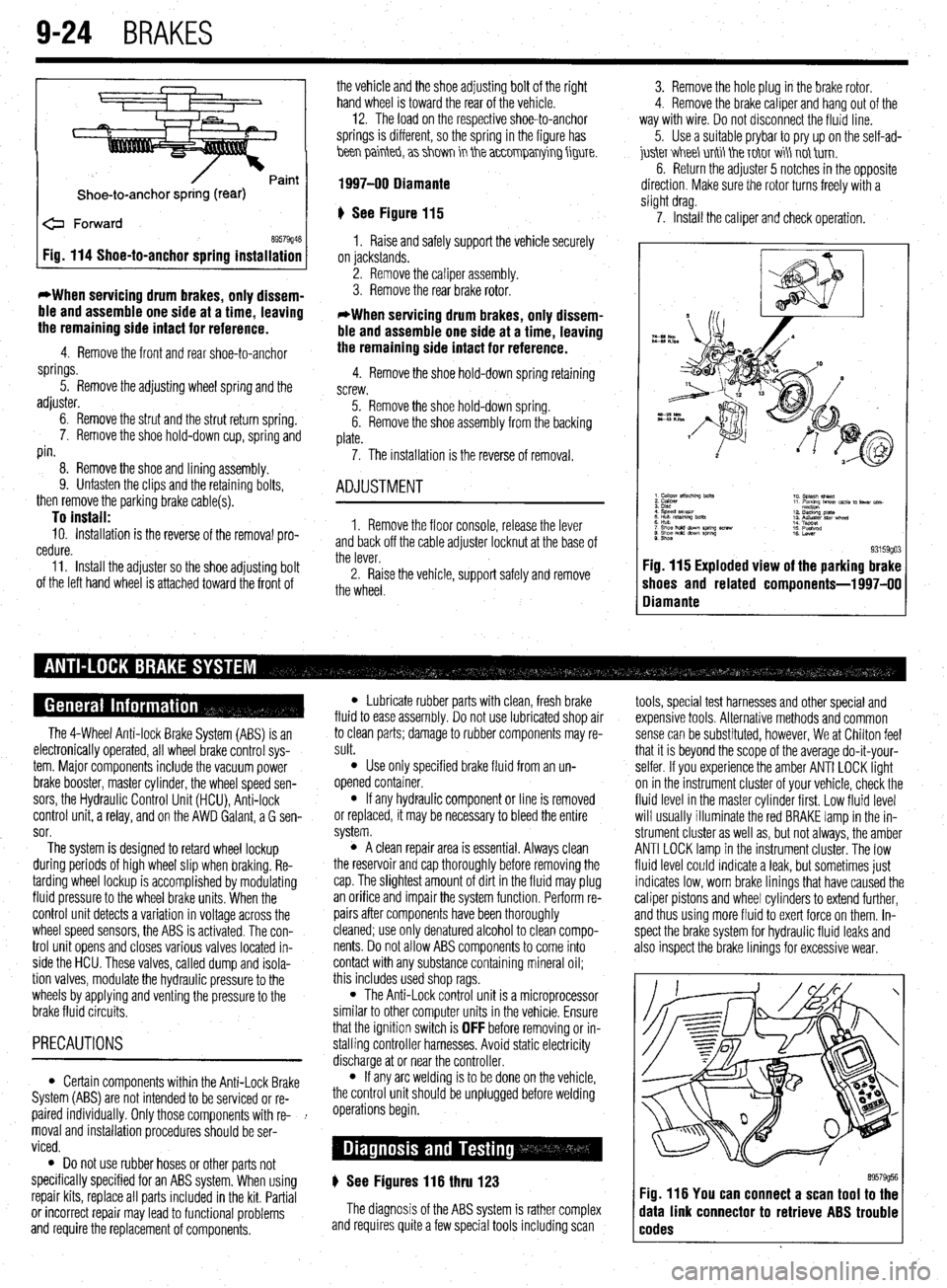
Shoe-to-anchor spring (rear)
e Forward
69579946 Fig. 114 Shoe-to-anchor spring installation
*When servicing drum
brakes, only dissem-
ble and assemble one side at a time, leaving
the remaining side intact for reference.
4. Remove the front and rear shoe-to-anchor
springs.
5. Remove the adjusting wheel spring and the
adjuster.
6. Remove the strut and the strut return spring.
7. Remove the shoe hold-down cup, spring and
pin.
8. Remove the shoe and lining assembly.
9. Unfasten the clips and the retaining bolts,
then remove the parking brake cable(s).
To install: 10. Installation is the reverse of the removal pro-
cedure.
11. Install the adjuster so the shoe adjusting bolt
of the left hand wheel is attached toward the front of the vehicle and the shoe adjusting bolt of the right
hand wheel is toward the rear of the vehicle. -
12. The load on the respective shoe-to-anchor
springs is different, so the spring in the figure has
hen painteb, a> shm in the a~~0mparrying figure.
1997-00 Diamante
‘) See Figure 115
1. Raise and safely support the vehicle securely
on jackstands.
2. Remove the caliper assembly.
3. Remove the rear brake rotor.
*When servicing drum brakes, only dissem-
ble and assemble one side at a time, leaving
the remaining side intact for reference.
4. Remove the shoe hold-down spring retaining
screw.
5. Remove the shoe hold-down spring.
6. Remove the shoe assembly from the backing
plate.
7. The installation is the reverse of removal.
ADJUSTMENT
1. Remove the floor console, release the lever
and back off the cable adjuster locknut at the base of
the lever.
2. Raise the vehicle, support safely and remove
the wheel. 3. Remove the hole plug in the brake rotor.
4. Remove the brake caliper and hang out of the
way with wire. Do not disconnect the fluid line.
5. Use a suitable prybar to pry up on the self-ad-
juskr V&I&I unti tie T&IT wi\ not tirn.
6. Return the adjuster 5 notches in the opposite
direction. Make sure the rotor turns freely with a
slight drag.
7. Install the caliper and check operation.
9. Shoe 93159go3 Fig. 115 Exploded view of the parking brake
shoes and related components-l 997-00
Diamante
The 4-Wheel Anti-lock Brake System (ABS) is an
electronically operated, all wheel brake control sys-
tem. Major components include the vacuum power
brake booster, master cylinder, the wheel speed sen-
sors, the Hydraulic Control Unit (HCU), Anti-lock
control unit, a relay, and on the AWD Galant, a G sen-
sor.
The system is designed to retard wheel lockup
during periods of high wheel slip when braking. Re-
tarding wheel lockup is accomplished by modulating
fluid pressure to the wheel brake units. When the
control unit detects a variation in voltage across the
wheel speed sensors, the ABS is activated. The con-
trol unit opens and closes various valves located in-
side the HCU. These valves, called dump and isola-
tion valves, modulate the hydraulic pressure to the
wheels by applying and venting the pressure to the
brake fluid circuits.
PRECAUTIONS
l Certain components within the Anti-Lock Brake
System (ABS) are not intended to be serviced or re-
paired individually. Only those components with re- !
moval and installation procedures should be ser-
viced.
0 Do not use rubber hoses or other parts not
specifically specified for an ABS system. When using
repair kits, replace all parts included in the kit. Partial
or incorrect repair may lead to functional problems
and require the replacement of components.
l Lubricate rubber parts with clean, fresh brake
fluid to ease assembly. Do not use lubricated shop air
to clean parts; damage to rubber components may re-
sult.
l Use only specified brake fluid from an un-
opened container.
l If any hydraulic component or line is removed
or replaced, it may be necessary to bleed the entire
system.
l A clean repair area is essential. Always clean
the reservoir and cap thoroughly before removing the
cap. The slightest amount of dirt in the fluid may plug
an orifice and impair the system function. Perform re-
pairs after components have been thoroughly
cleaned; use only denatured alcohol to clean compo-
nents. Do not allow ABS components to come into
contact with any substance containing mineral oil;
this includes used shop rags.
l The Anti-Lock control unit is a microprocessor
similar to other computer units in the vehicle. Ensure
that the ignition switch is
OFF before removing or in-
stalling controller harnesses. Avoid static electricity
discharge at or near the controller.
l If any arc welding is to be done on the vehicle,
the control unit should be unplugged before welding
operations begin.
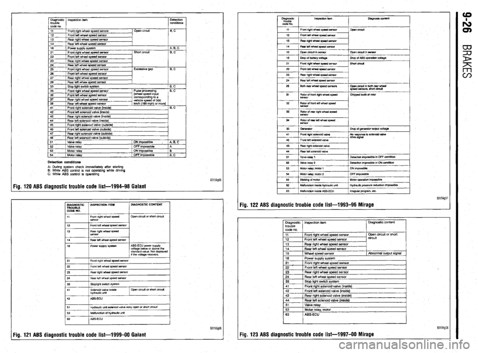
) See Figures 116 thru 123
The diagnosis of the ABS system is rather complex
and requires quite a few special tools including scan tools, special test harnesses and other special and
expensive tools. Alternative methods and common
sense can be substituted, however, We at Chilton feel
that it is beyond the scope of the average do-it-your-
selfer. If you experience the amber ANTI LOCK light
on in the instrument cluster of your vehicle, check the
fluid level in the master cylinder first. Low fluid level
will usually illuminate the red BRAKE lamp in the in-
strument cluster as well as, but not always, the amber
ANTI LOCK lamp in the instrument cluster. The low
fluid level could indicate a leak, but sometimes just
indicates low, worn brake linings that have caused the
caliper pistons and wheel cylinders to extend further,
and thus using more fluid to exert force on them. In-
spect the brake system for hydraulic fluid leaks and
also inspect the brake linings for excessive wear.
89579956 Fig. 116 You can connect a scan tool to the
data link connector to retrieve ABS trouble
codes
Page 361 of 408
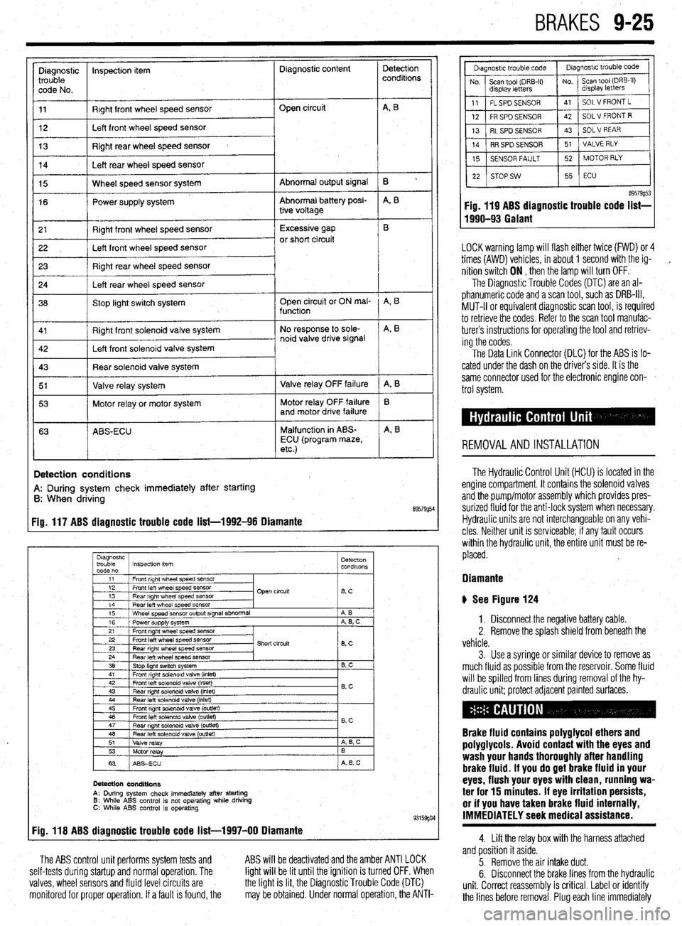
BRAKES 9-25
Diagnostic inspection item Diagnostic content
trouble
code No.
11 Right front wheel speed sensor
12 Left front wheel speed sensor Open circuit
13 Right rear wheel speed sensor
14 Left rear wheel speed sensor
Abnormal output signal
Abnormal battery posi-
tive voltage 15 Wheel speed sensor system
16 Power supply system
r 21
I Right front wheel speed sensor 1 Excessive gap
22 I Left front wheel speed sensor or short circuit
23 Right rear wheel speed sensor
24 Left rear wheel speed sensor
36 Stop light switch system Open circuit or ON mal-
function
Right front solenoid valve system
I 5’ I Valve relay system 1 Valve relay OFF failure
I 53 1 Motor relay or motor system Motor relay OFF failure
and motor drive failure
63 ABS-ECU Malfunction in ABS-
ECU (program maze,
etc.)
I
!
Detection
conditions
B ’
A, B
A, B
A, B
A, 8
B
A, B
Detection conditions
A: During system check immediately after starting
B: When driving
89579954 Fig. 117 ABS diagnostic trouble code list-1992-96 Diamante
Diagnostrc
trouble Inspection item Detectron
code no. condalons
1
11 1 Front right wheel speed SensOr
I
I I
12 1 Front left wheel speed sensor
13 1 Rear right wheel speed sensor Open circuit
lBsC I
14
Rear left wheel speed sensor
15 Wheel speed sensor output signal abnormal
16 Power supply system
21 Front right wheel speed sensor A B
A, B, C
22 Front left wheel speed sensor
23 Rear right wheel speed sensor
24 Rear left wheel speed sensor
38 Stop light switch system Short circuit
8, c
B. C
41 1 Front right solenoid valve (inlet)
I I
42
Front left solenoid valve (inlet)
43 Rear right solenord valve (inlet) 0.c
44 Rear left solenoid valve (inlet)
45 Front right solenoid valve (outlet)
46 Front left solenoid valve (outlet)
47
Rear nght solenoid valve (outret) - B,C
48 Rear left solenoid valve (outlet)
51
Valve relay A 6, c
53
Motor relay B
63 ABSECU A B, c
Detection conditions
A: During system check immediately after starting 6: While ABS control is not operating while driving C: While ABS control is operating 93159go4 Fig. 118 ABS diagnostic trouble code list-1997-00 Diamante
The ABS control unit performs system tests and
self-tests during startup and normal operation. The
valves, wheel sensors and fluid level circuits are
monitored for proper operation. If a fault is found, the ABS will be deactivated and the amber ANTI LOCK
light will be lit until the ignition is turned OFF. When
the light is lit, the Diagnostic Trouble Code (DTC)
may be obtained. Under normal operation, the ANTI-
89579g53 Fig. 119 ABS diagnostic trouble code list-
1990-93 Galant
LOCK warning lamp will flash either twice (FWD) or 4
times (AWD) vehicles, in about 1 second with the ig-
,
nition switch ON , then the lamp will turn OFF.
The Diagnostic Trouble Codes (DTC) are an al-
phanumeric code and a scan tool, such as DRB-III,
MUT-II or equivalent diagnostic scan tool, is required
to retrieve the codes. Refer to the scan tool manufac-
turers instructions for operating the tool and retriev-
ing the codes.
The Data Link Connector (DLC) for the ABS is lo-
cated under the dash on the driver’s side. It is the
same connector used for the electronic engine con-
trol system.
REMOVALANDINSTALLATION
The Hydraulic Control Unit (HCU) is located in the
engine compartment. It contains the solenoid valves
and the pump/motor assembly which provides pres-
surized fluid for the anti-lock system when necessary.
Hydraulic units are not interchangeable on any vehi-
cles Neither unit is serviceable; if any fault occurs
within the hydraulic unit, the entire unit must be re-
placed.
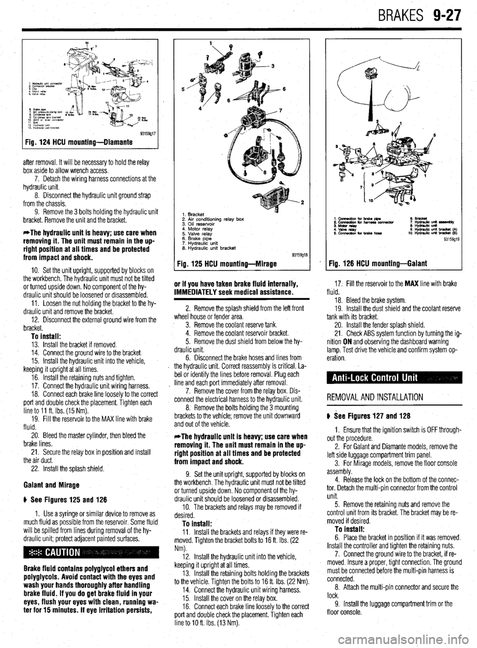
Diamante
b See Figure 124
1. Disconnect the negative battery cable.
2. Remove the splash shield from beneath the
vehicle.
3. Use a syringe or similar device to remove as
much fluid as possible from the reservoir. Some fluid
will be spilled from lines during removal of the hy-
draulic unit; protect adjacent painted surfaces.
Brake fluid contains polyglycol ethers and
poly9lycols. Avoid contact with the eyes and
wash your hands thoroughly after handling
brake fluid. If you do 9et brake fluid in your
eyes, flush your eyes with clean, running wa-
ter for 15 minutes. If eye irritation persists,
or if you have taken brake fluid internally,
IMMEDIATELY seek medical assistance.
4. Lift the relay box with the harness attached
and position it aside.
5. Remove the air intake duct.
6. Disconnect the brake lines from the hydraulic
unit. Correct reassembly is critical. Label or identify
the lines before removal. Plug each line immediately
Page 362 of 408
Diagnostic InspeclM item
trouble
code no. Detection
conditions
11 Front right wheel speed sensor
12 Front left wheel speed sensor
13 Rear right wheel speed sensor Open circuit
6 c
14
Rear left wheel speed sensor
16
Power supply system
21 Front right wheel speed sensor
22 Front left wheel speed sensor Short circuit 4 0. C
0, c
23
Rear right wheel speed sensof
24 Rear left wheel speed sensor
25 Front right wheel speed sensor
26 Front left wheel speed sensor Excessive gap
B, c
27 / Rear right wheel speed sensor
26 1 Rear left wheel speed sew
33
Stop light switch system
35 Front right wheel speed sensor
36 Front left wheel speed sensor
37 Rear right wheel speed sensor Pulse orocessina
pheei speed in&t
corresponding to a
vehicle speed of 300
46 Rear left solenoid valve (outside)
51
Valve relay
52 Vti relay
53
Motor relay
54
Motor relay ON impossible ,
A B. C
OFF impossrble
A
ON impossible
B
OFF impossible
B, c
Detection conditions A: During system check immediately after starting
8: While ABS control is not operating while driving
C: While ABS control is operating
Fig. 120 ABS diagnostic trouble code list-1994-98 Galant 93159go5
DIAGNOSTIC INSPECTION IT’EH DIAGNOSTIC CONTENT
TROUBLE
CODE NO.
11 Front right wheel speed
Sensor Open circuit or short circuit
12
13 Front left wheel speed sensor
Rear right wheel speed
SBnsor
14
16 Fear left wheel speed ssnsor
Power supply system ABS-ECU power supply
voltage below or above the
standard value. Not displayed
if the voltage recovers.
21 Front right wheel speed sensor
22 Front left wheel speed sensor
23 Rear right whesl sped sensor
~
Hydraulic unit aolenoid valve relay open or short circuit
93159906
Fig. 121 ABS diagnostic trouble code list-1999-00 Galant Fig. 122 ABS diagnostic trouble code list-1993-96 Mirage
Page 363 of 408
BRAKES 9-27
93159g17
Fig. 124 HCU mounting-Diamante
after removal. It will be necessary to hold the relay
box aside to allow wrench access.
7. Detach the wiring harness connections at the
hydraulic unit.
8. Disconnect the hydraulic unit ground strap
from the chassis.
9. Remove the 3 bolts holding the hydraulic unit
bracket. Remove the unit and the bracket.
*The hydraulic unit is heavy; use care when
removing it. The unit must remain in the up-
right position at all times and be protected
from impact and shock.
IO. Set the unit upright, supported by blocks on
the workbench. The hydraulic unit must not be tilted
or turned upside down. No component of the hy-
draulic unit should be loosened or disassembled.
11. Loosen the nut holding the bracket to the hy-
draulic unit and remove the bracket.
12. Disconnect the external ground wire from the
bracket.
To install: 13. Install the bracket if removed.
14. Connect the ground wire to the bracket.
15. Install the hydraulic unit into the vehicle,
keeping it upright at all times.
16. Install the retaining nuts and tighten.
17. Connect the hydraulic unit wiring harness.
18. Connect each brake line loosely to the correct
port and double check the placement. Tighten each
line to 11 ft. Ibs. (15 Nm).
19. Fill the reservoir to the MAX line with brake
fluid.
20. Bleed the master cylinder, then bleed the
brake lines.
21. Secure the relay box in position and install
the air duct.
22. Install the splash shield.
Galant and Mirage
ti See Figures 125 and 126
1. Use a syringe or similar device to remove as
much fluid as possible from the reservoir. Some fluid
will be spilled from lines during removal of the hy-
draulic unit; protect adjacent painted surfaces.
Brake fluid contains polyglycol ethers and
polyglycols. Avoid contact with the eyes and
wash your hands thoroughly after handling
brake fluid. If you do get brake fluid in your
eyes, flush your eyes with clean, running wa-
ter for 15 minutes. If eye irritation persists,
1. Bracket
2. Air conditioning relay box
3. Oil reservoir
4. Motor relay
5. Valve relay
6. Brake pipe
7. Hydraulic unit
8. Hydraulic unit bracket
Fig. 125 HCU mounting-Mirage
or if you have taken brake fluid internally,
17. Fill the reservoir to the MAX line with brake IMMEDIATELY seek medical assistance. fluid.
2. Remove the splash shield from the left front
wheel house or fender area.
3. Remove the coolant reserve tank.
4. Remove the coolant reservoir bracket.
5. Remove the dust shield from below the hy-
draulic unit.
6. Disconnect the
brake hoses and lines from
the hydraulic unit. Correct reassembly is critical. La-
bel or identify the lines before removal. Plug each
line and each port immediately after removal.
7. Remove the cover from the relay box. Dis-
connect the electrical harness to the hydraulic unit.
8. Remove the bolts holding the 3 mounting
brackets to the vehicle; remove the unit downward
and out of the vehicle. 18. Bleed the brake system.
19. Install the dust shield and the coolant reserve
tank with its bracket.
20. Install the fender splash shield.
21. Check ABS system function by turning the ig-
nition ON and observing the dashboard warning
lamp. Test drive the vehicle and confirm system op-
eration.
REMOVALANDINSTALLATION
) See Figures 127 and 128
*The hydraulic unit is heavy; use care when
removing it. The unit must remain in the up-
right position at all times and be protected
from impact and shock.
9. Set the unit upright, supported by blocks on
the workbench. The hydraulic unit must not be tilted
or turned upside down. No component of the hy-
draulic unit should be loosened or disassembled.
10. The brackets and relays may be removed if
desired.
To install: 11. Install the brackets and relays if they were re-
moved. Tighten the bracket bolts to 16 ft. Ibs. (22
Nm). 1. Ensure that the ignition switch is OFF through-
out the procedure.
2. For Galant and Diamante models, remove the
left side luggage compartment trim panel.
3. For Mirage models, remove the floor console
assembly.
4. Release the lock on the bottom of the connec-
tor. Detach the multi-pin connector from the control
unit.
12. Install the hydraulic unit into the vehicle,
keeping it upright at all times.
13. Install the retaining bolts holding the brackets
to the vehicle. Tighten the bolts to 16 ft. Ibs. (22 Nm).
14. Connect the hydraulic unit wiring harness.
15. Install the cover on the relay box.
16. Connect each brake line loosely to the correct
port and double check the placement. Tighten each
line to IO ft. Ibs. (13 Nm). 5. Remove the retaining nuts and remove the
control unit from its bracket. The bracket may be re-
moved if desired. To install: 6. Place the bracket in position if it was removed.
Install the controller and tighten the retaining nuts.
7. Connect the ground wire to the bracket, if re-
moved. Insure a proper, tight connection. The ground
must be connected before the multi-pin harness is
connected.
8. Attach the multi-pin connector and secure the
lock.
9. Install the luggage compartment trim or the
floor console.
Fig. 126 HCU mounting-Galant
Page 376 of 408
IO-8 BODYANDTRIM
cFroni 1990 ma&Is>
1 Plug
2 Knee pr&ctor assembb
3 lnsuumen~ under covet assembly
4. Column lxwer. lower :
5. Column cover upper
6 Lap shower duct and foot shcwai nozzle
7 Ttlt bracket installalm bolts
0 Undercover
9. stopper
10 Glove box assembly
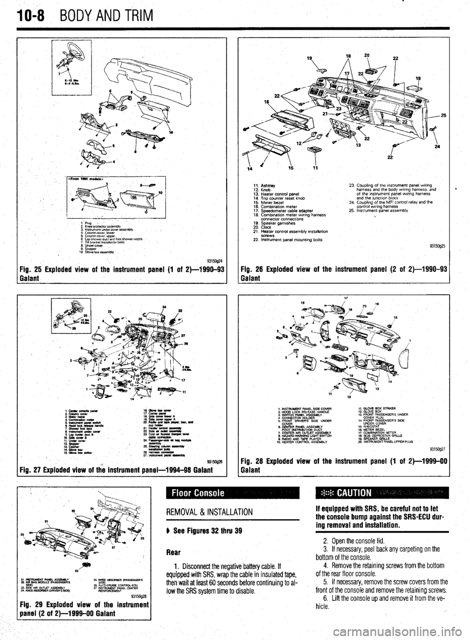
93150@4 Fig. 25 Exploded view of the instrument panel (1 of 2)-1990-93 Fig. 26 Exploded view of the instrument panel (2 of 2)-1990-93
Galant Galant
1.CUllUCU+RC&pllU 16. Gbve bm eewr
i: iiiikz!!T 17. cucw gmnl
4. Cfnnbinuion meta 19. qds cww bww A
5 ‘~fiJzg%L L: ,“zr&, beat. md
21 L% sssemuy
8lmwmemu&cowr 236&1ou(W~
S.LapOdrduQB
10. slds cw4# B 23 ~u,~e-
11. LIdsI corn
::: s%ZZ
14. Gbw bx / ;:+q-=:-
kmasa
IS. Gkw ba SIiikw 2&HWSSCCl!ZL
2rtnsmlmuapr*lrvrnbly
@ma
Fig. 27 Exploded view of the instrument panel-1994-98 Galant
1;. p;;w
13: Heater control panel
14. Trip counter reset knob
15. Meter bezel
16. Combination meter
17. Speedometer cable adapter
18. Combrnatron meter wiring harness
connector connecttons
19. Speaker garnrshes
20. Clock 23. Coupling of the Instrument panel wiring
harness and the body wiring harness, and
of the Instrument panel wrring harness
and the junctlon block
24. Coupling of the MFI control relay and the
control wiring harness
25. Instrument panel assembly
21. Heater control assembly installation
9C?WS 22. Instrument panel mounting bolts
93150925
1. INSTRUMENT PANEL SIDE COVER
2. HOOD LOCK RELEASE HANDLE
3. SWITCH PANEL ASSEMBLY
4 CONNECTOR H+DER
5. ER DRIVERS SIDE UNDER
6. CENTER PANEL ASSEMBLY
FOOT MSTRISUTION DUCT
7. CENTER AIR OUTLET ASSEMBLY
8. HAZARO WARNING LIGHT SWfTCti
9. RADIO AN0 TAPE PLAYER
10. H!ZATER CONTROL ASSEMBLY 1,. GLOV2 BOX STRIKER
12. GLOVE SOX
13 FRONT PASSENGER’S UNOER
COVER PLUG
14. FRONT PASSENGER’S SIDE
UNDER COVER
15. RHEOSTAT
16. METER BEZEL
17. COMBINATION METER
18. SIDE DEFROSTER GRILLE
19 SPEAKER GRILLE
mo. INSTRUMENT PANEL UPPER PLUG
93159927
Fig. 28 Exploded view of the instrument panel (1 of 2)-1999-00
Galant
~~~~~~~~~
Fig. 29 Exploded view of the instrument
REMOVAL &INSTALLATION
) See Figures 32 thru 39 If equipped with SRS, be careful not to let
the console bump against the SRS-ECU dur-
ing removal and installation.
Rear 2. Open the console lid. 3. If necessary, peel back any carpeting on the
bottom of the console.
1. Disconnect the negative battery cable. If
equipped with SRS, wrap the cable in insulated tape,
then wait at least 60 seconds before continuing to al-
low the SRS system time to disable.
4. Remove the retaining screws from the bottom
of the rear floor console.
5. If necessary, remove the screw covers from the
front of the console and remove the retaining screws.
6. Lift the console up and remove it from the ve-
hicle.
rb