1900 MITSUBISHI DIAMANTE open gas tank
[x] Cancel search: open gas tankPage 199 of 408
5-12 FUELSYSTEM
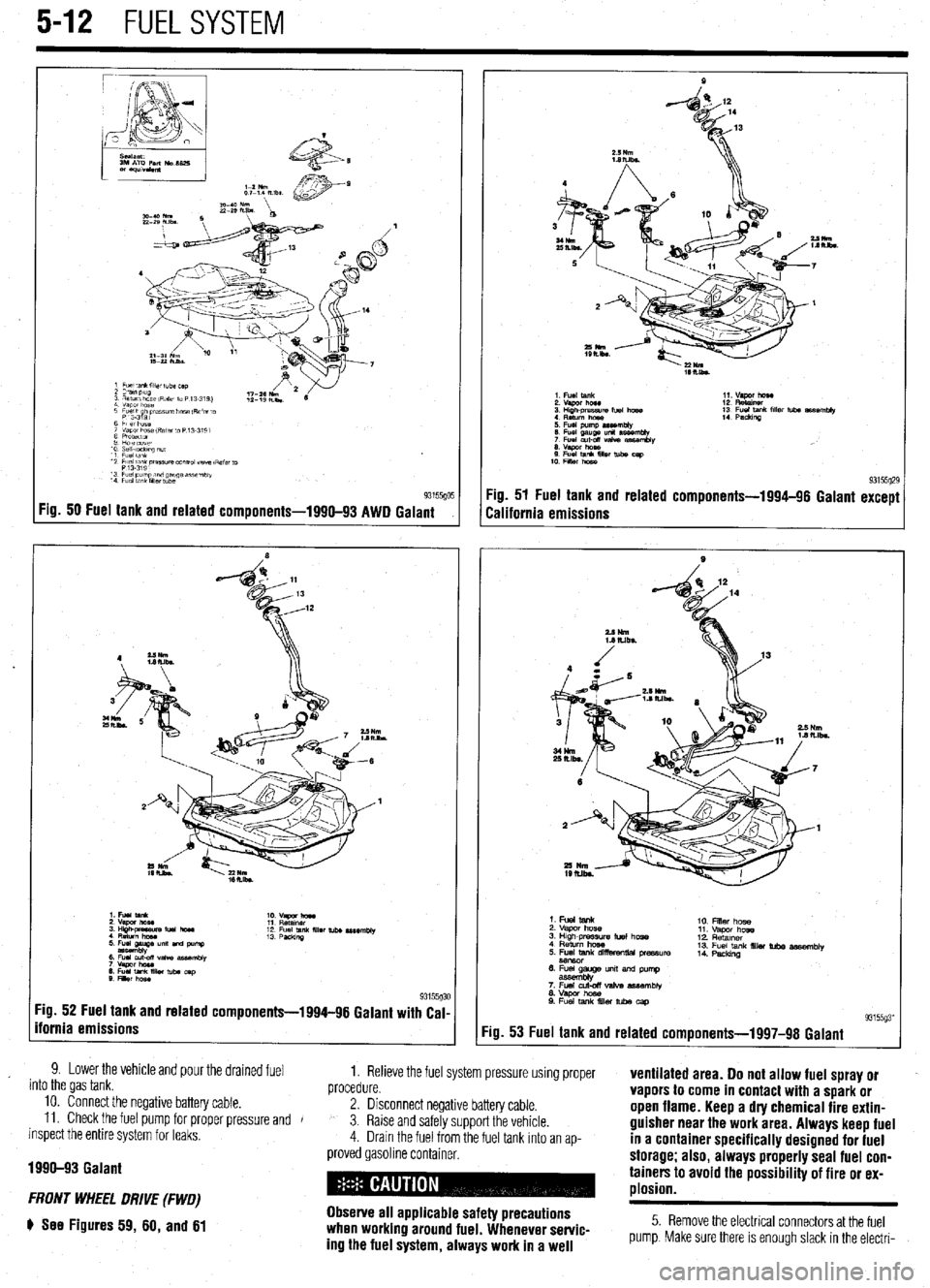
Fig. 50 Fuel tank and related components-1990-93 AWD Galant
:ig. 52 Fuel tank and related components-1994-96 Galant with Cal-
fornia emissions
9. Lower the vehicle and pour the drained fuel
into the gas tank. 1. Relieve the fuel system pressure using proper
procedure. ventilated area. Do not allow fuel spray or
10. Connect the negative battery cable.
11. Check the fuel pump for proper pressure and 2. Disconnect negative battery cable. vapors to come in contact with a spark or
J
inspect the entire system for leaks, 3. Raise and safely support the vehicle. open flame. Keep a dry chemical fire extin-
4. Drain the fuel from the fuel tank Into an ap- guisher near the work area. Always keep fuel
in a container specifically designed for fuel
1990-93 Galant
FRONT WHEEL DRIVE (FWD)
e See Figures 59, 60, and 61
proved gasoline container. storage; also, always properly seal fuel con-
tainers to avoid the possibility of fire or ex-
plosion.
Observe all applicable safety precautions
when working around fuel. Whenever servic-
ing the fuel system, always work in a well
5. Remove the electrical connectors at the fuel
pump. Make sure there is enough slack in the electri-
Page 201 of 408
.
5-14 FUEL SYSTEM
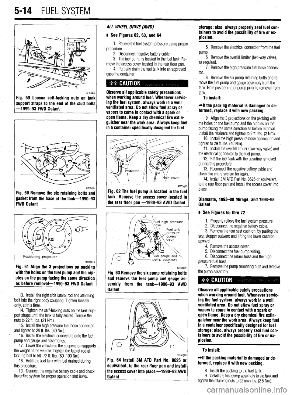
93155(10: ‘ig. 59 loosen self-locking nuts on tank
mpporf straps to the end of the stud bolts
-1990-93 FWD Galant
93i55Qo$ :ig. 60 Remove the six retaining bolts and
lasket from the base of the tank-1990-93
:WD Galant
Q m
0 a
cl@=
u a-
a al2
0
0
Q
a a
Posmdmng projectton 93155910 Fig. 61 Align the 3 projections on packing
with the holes on the fuel pump and the nip-
ples on the pump facing the same direction
as before removal-1990-93 FWD Galant
13. Install the right side lateral rod and attaching
bolt into the right body coupling. Tighten loosely
only, at this time.
14. Tighten the self-locking nuts on the tank sup-
port straps until the tank is fully seated. Torque the
nuts to 22 ft. Ibs. (31 Nm).
15. Install the high pressure fuel hose connector
and tighten to 29 ft. Ibs. (40 Nm).
16. Install the electrical connectors onto the fuel
pump and gauge unit assemblies.
17. Lower the vehicle so the suspension supports
the weight of the vehicle. Tighten the lateral rod at-
taching bolt to 58-72 ft Ibs. (So-100 Nm).
18. Refill the fuel tank with fuel drained during
this procedure.
19. Connect the negative battery cable and check
the entire system for proper operation and leaks. ALL WHEEL DRIVE (A WO)
# See Figures 62, 63, and 64
1. Relieve the fuel system pressure using proper
procedure.
2. Disconnect negative battery cable.
3. The fuel pump is located in the fuel tank. Re-
move the access cover located in the rear floor pan
4 Parbally drain the fuel tank into an approved
gasoline container.
Observe all applicable safety precautions
when workina around fuel. Whenever servic-
ing the fuel system, always work in a well
ventilated area. Do not allow fuel spray or
vapors to come in contact with a spark or
open flame. Keep a dry chemical fire extin-
guisher near the work area. Always keep fuel
in a container specifically designed for fuel
-ig. 62 The fuel pump is located in the fuel
r
ank. Remove the access cover located m
he rear floor pan -1990-93 AWD Galant
93155go7 Fig. 63 Remove the six pump retaining bolts
and remove the fuel pump and gauge as-
sembly from the tank-1990-93 AWD
1 Galant
93155goa Fig. 64 Install 3M ATD Part No. 8625 or
equivalent, to the rear floor pan and install
ihe access cover into place -1990-93 AWD
Ealant storage; also, always properly seal fuel con-
tainers to avoid the possibility of fire or ex-
plosion.
5 Remove the electrical connector from the fuel
pump.
6. Remove the overfill limiter (two-way valve),
as required.
7. Remove the high pressure fuel hose connec-
tor.
8. Remove the six pump retaming bolts and re-
move the fuel pump and gauge assembly from the
tank. Note positioning of pump prior to removal from
tank.
To install:
*If the packing material is damaged or de-
formed, replace it with new packing.
9. Align the 3 projections on the packing with
the holes on the fuel pump and the nipples on the
pump facmg the same direction as before removal.
Install the retainers and tlghten to 2 ft. Ibs. (3 Nm).
10. Install the high pressure hose connection and
tighten to 29 ft. Ibs. (40 Nm).
11. Install the overfill limiter (two-way valve) and
the electrical connector to the fuel pump.
12. Fill the fuel tank with the gasoline removed
during this procedure.
13. Reconnect the negative battery cable and
check the entire system for leaks.
14. Install 3M ATD Part No. 8625 or equivalent,
to the rear floor pan and install the access cover into
place.
Diamante, 1993-00 Mirage, and 1994-98
Galant
# See Figures 65 thru 72
1. Properly relieve the fuel system pressure.
2. Disconnect the negative battery cable.
3. Remove the rear seat cushion, by pulling the
seat stopper outward and lifting the lower cushion
upward.
4. Remove the access cover.
5. Disconnect the fuel pump wiring.
6. Disconnect the return hose and the high
pressure fuel hose.
7. Remove the pump mounting nuts and remove
the pump assembly.
Observe all applicable safety precautions
when working around fuel. Whenever servic-
ing the fuel system, always work in a well
ventilated area. Do not allow fuel spray or
vapors to come in contact with a spark or
open flame. Keep a dry chemical fire extin-
guisher near the work area. Always keep fuel
in a container specifically designed for fuel
storage; also, always properly seal fuel con-
tainers to avoid the possibility of fire or ex-
plosion.
To install:
rlf the packing material is damaged or de-
formed, replace it with new packing.
8. Install the packing to the fuel tank.
9. Install the fuel pump assembly to the tank and
tighten the retaining nuts to 22 inch Ibs. (2 5 Nm).
Page 203 of 408
.
5-16 FUELSYSTEM
6. Disconnect the return hose and the high
pressure fuel hose.
7. Using special tool MB991480 or equivalent,
remove the fuel pump retaining cap and remove the
pump assembly.
Observe all applicable safety precautions
when working around fuel. Whenever servic-
ing the fuel system, always work in a well
ventilated area. Do not allow fuel spray or
vapors to come in contact with a spark or
open flame. Keep a dry chemical fire extin-
guisher near the work area. Always keep fuel
in a container specifically designed for fuel
storage; also, always properly seal fuel con-
tainers to avoid the possibility of fire or ex-
plosion.
To install:
*If the packing material is damaged or de-
formed, replace it with new packing.
8. Install the packing to the fuel tank.
9. Install the fuel pump assembly to the tank
and align the mating marks on the pump and the
floorpan.
10. Tighten the fuel pump retaining cap using
tool MB991480 or equrvalent.
11. Connect the high pressure hose, return hose
and the fuel tank wirmg.
12. Connect the negative battery cable.
13. Check the fuel pump for proper pressure and
inspect the entire system for leaks.
14. Apply sealant to the access cover and install
the cover.
15. Install the rear seat cushion.
TESTING
1. Relieve fuel system pressure.
2. Disconnect the battery negative cable.
3. Disconnect the fuel hrgh pressure hose at the
delivery pipe side.
Observe all applicable safety precautions
when working around fuel. Whenever servic-
ing the fuel system, always work in a well
ventilated area. Do not allow fuel spray or
vapors to come in contact with a spark or
open flame. Keep a dry chemical fire extin-
guisher near the work area. Always keep fuel
in a container specifically designed for fuel
storage; also, always properly seal fuel con-
tainers to avoid the possibility of fire or ex-
alosion.
4. Connect a fuel pressure gauge to tools
MD998709 and MD998742 or exact equivalent, with
appropriate adapters, seals and/or gaskets to prevent
leaks during the test. Install the gauge and adapter
between the delivery pipe and high pressure hose. In-
stall carefully to prevent leaks.
5. Connect the negative battery cable.
6. Apply battery voltage to the terminal for fuel
pump activation (located in the engine compartment)
to run the fuel pump, and check for leaks.
7. Start the engine and run at curb idle speed.
8. Measure the fuel pressure and compare to
the specifications listed in the chart in Section 1.
9. Locate and disconnect the vacuum hose run-
ning to the fuel pressure regulator. Plug the end of
the hose and record the fuel pressure again. The fuel
pressure should have increased approximately IO
psi. 10. Reconnect the vacuum hose the fuel pressure
regulator. After the fuel pressure stabilizes, race the
engine 2-3 times and check that the fuel pressure
does not fall when the engine is running at idle.
il. Check to be sure there is fuel pressure in the
return hose by gently pressing the fuel return hose
with fingers while racing the engine. There will be no
fuel pressure in the return hose when the volume of
fuel flow is low.
12. If fuel pressure is too low, check for a
clogged fuel filter, a defective fuel pressure regulator
or a defective fuel pump, any of which will require re-
placement.
13. If fuel pressure is too high, the fuel pressure
regulator is defective and will have to be replaced or
the fuel return is bent or clogged. If the fuel pressure
readmg does not change when the vacuum hose is
disconnected, the hose is clogged or the valve is
stuck in the fuel pressure regulator and it will have to
be replaced.
14. Stop the engine and check for changes in the
fuel pressure gauge. It should not drop. If the gauge
reading does drop, watch the rate of drop. If fuel
pressure drops slowly, the likely cause is a leaking
injector which will require replacement. If the fuel
pressure drops immediately after the engine is
stopped, the check valve in the fuel pump isn’t clos-
ing and the fuel pump will have to be replaced.
15. Relieve fuel system pressure.
16. Disconnect the high pressure hose and re-
move the fuel pressure gauge from the delivery pipe.
17. Install a new O-ring in the groove of the high
pressure hose. Connect the hose to the delivery pipe
and tighten the screws. After Installation, apply bat-
tery voltage to the terminal for fuel pump activation to
run the fuel pump. Check for leaks.
Page 389 of 408
TROUBLESHOOiNG 11-7
4. Starter motor spins, but does not engage
a. Check the starter motor for a seized or binding pinion gear.
b. Remove the flywheel inspection plate and check for a damaged ring gear.
Gasoline Engines
1. Engine runs poor/y, hesiiates
a. Check the engine ignition system operation and adjust if possible, or replace defective
parts.
b. Check for restricted fuel injectors and replace as necessary.
c. Check the fuel pump output and delivery. Inspect fuel lines for restrictions. If the fuel
pump pressure is below specification, replace the fuel pump.
d. Check the operation of the engine management system and repair as necessary.
2. Enfline lacks power
a. Check the engine’s tune-up status. Note the tune-up specifications and check for items
such as severely worn spark plugs; adjust or replace as needed. On vehicles with
manually adjusted valve clearances, check for tight valves and adjust to specification.
b. Check the air filter and air intake system. Replace the air filter if it is dirty or contami-
nated. Check the fresh air intake system for restrictions or blockage.
c. Check the operation of the engine fuel and ignition management systems. Check the
sensor operation and wiring. Check for low fuel pump pressure and repair or replace
components as necessary.
d. Check the throttle linkage adjustments. Check to make sure the linkage is fully open-
ing the throttle. Replace any worn or defective bushings or linkages.
e. Check for a restricted exhaust system. Check for bent or crimped exhaust pipes, or in-
ternally restricted mufflers or catalytic converters. Compare inlet and outlet tempera-
tures for the converter or muffler. If the inlet is hot, but outlet cold, the component is
restricted.
f. Check for a loose or defective knock sensor. A loose, improperly torqued or defective
knock sensor will decrease spark advance and reduce power. Replace defective knock
sensors and install using the recommended torque specification.
g. Check for engine mechanical conditions such as low compression, worn piston rings,
worn valves, worn camshafts and related parts. An engine which has severe mechani-
cal wear, or has suffered internal mechanical damage must be rebuilt or replaced to re-
store lost power.
h. Check the engine oil level for being overfilled. Adjust the engine’s oil level, or change
the engine oil and filter, and top off to the correct level.
i. Check for an intake manifold or vacuum hose leak. Replace leaking gaskets or worn
vacuum hoses.
j. Check for dragging brakes and replace or repair as necessary.
k. Check tire air pressure and tire wear. Adjust the pressure to the recommended set-
tings. Check the tire wear for possible alignment problems causing increased rolling
resistance, decreased acceleration and increased fuel usage.
I. Check the octane rating of the fuel used during refilling, and use a higher octane rated
fuel.
3. Poor fuel economy
a. Inspect the air filter and check for any air restrictions going into the air filter housing.
Replace the air filter if it is dirty or contaminated.
b. Check the engine for tune-up and related adjustments. Replace worn ignition parts,
check the engine ignition timing and fuel mixture, and set to specifications if possible.
c. Check the tire size, tire wear, alignment and tire pressure. Large tires create more
rolling resistance, smaller tires require more engine speed to maintain a vehicle’s road
speed. Excessive tire wear can be caused by incorrect tire pressure, incorrect wheel
alignment or a suspension problem. All of these conditions create increased rolling
resistance, causing the engine to work harder to accelerate and maintain a vehicle’s
speed.
d. Inspect the brakes for binding or excessive drag. A sticking brake caliper, overly ad-
justed brake shoe, broken brake shoe return spring, or binding parking brake cable or
linkage can create a significant drag, brake wear and loss of fuel economy. Check the
brake system operation and repair as necessary.
4. Engine runs on (diesels) when turned off
a. Check for idle speed set too high and readjust to specification.
b. Check the operation of the idle control valve, and replace if defective.
c. Check the ignition timing and adjust to recommended settings.
Check for defective
sensors or related components and replace if defective.
d. Check for a vacuum leak at the intake manifold or vacuum hose
and replace defective
gaskets or hoses.
e. Check the engine for excessive carbon build-up in the combustion chamber. Use a
recommended decarbonizing fuel additive or disassemble the cylinder head to remove
the carbon.
f. Check the operation of the engine fuel management system and replace defective sen-
sors or control units.
g. Check the engine operating temperature for overheating and repair as necessary. 5. Engine knocks and pinfls during heavy accele/ation, and on steep hills
a. Check the octane rating of the fuel used during refilling, and use a higher octane rated
fuel.
b. Check the ignition timing and adjust to recommended settings. Check for defective
sensors or related components and replace if defective.
c. Check the engine for excessive carbon build-up in the combustion chamber. Use a
recommended decarbonizing fuel additive or disassemble the cylinder head to remove
the carbon.
d. Check the spark plugs for the correct type, electrode gap and heat range. Replace worn
or damaged spark plugs. For severe or continuous high speed use, install a spark plug
that is one heat range colder.
e. Check the operation of the engine fuel management system and replace defective sen-
sors or control units.
f. Check for a restricted exhaust system. Check for bent or crimped exhaust pipes, or in-
ternally restricted mufflers or catalytic converters. Compare inlet and outlet tempera-
tures for the converter or muffler. If the inlet is hot, but outlet cold, the component is
restricted.
6. Engine atxelerates, but vehicle does not gain speed
a. On manual transmission vehicles, check for causes of a slipping clutch. Refer to the
clutch troubleshooting section for additional information.
b. On automatic transmission vehicles, check for a slipping transmission” Check the
transmission fluid level and condition. If the fluid level is too high, adjust to the cor-
rect level. If the fluid level is low, top off using the recommended fluid type. If the fluid
exhibits a burning odor, the transmission has been slipping internally. Changing the
fluid and filter may help temporarily, however in this situation a transmission may re-
quire overhauling to ensure long-term reliability.
Diesel Engines
1. Engine runs pOOr!y a. Check the injection pump timing and adjust to specification.
b. Check for air in the fuel lines or leaks, and bleed the air from the fuel system.
c. Check the fuel filter, fuel feed and return lines for a restriction and repair as necessary.
d. Check the fuel for contamination, drain and flush the fuel tank and replenish with fresh
fuel.
2. Enfline lacks power
a. Inspect the air intake system and air filter for restrictions and, if necessary, replace the
air filter.
b. Verify the injection pump timing and reset if out of specification.
c. Check the exhaust for an internal restriction and replace failed parts.
d. Check for a restricted fuel filter and, if restricted, replace the filter.
e. Inspect the fuel filler cap vent. When removing the filler cap, listen for excessive hiss-
ing noises indicating a blockage in the fuel filler cap vents, If the filler cap vents are
blocked, replace the cap.
f. Check the fuel system for restrictions and repair as necessary.
g. Check for low engine compression and inspect for external leakage at the glow plugs
or nozzles. If no external leakage is noted, repair or replace the engine.
ENGINE PERFORMANCE TROUBLESHOOTING HINTS When troubleshooting an engine running or performance condition, the mechanical
condition of the engine should be determined before lengthy troubleshooting procedures
are performed.
The engine fuel management systems in fuel injected vehicles rely on electronic sen-
sors to provide information to the engine control unit for precise fuel metering. Unlike
carburetors, which use the incoming air speed to draw fuel through the fuel metering jets
in order to provide a proper fuel-to-air ratio, a fuel injection system provides a specific
amount of fuel which is introduced by the fuel injectors into the intake manifold or intake
port, based on the information provided by electronic sensors.
The sensors monitor the engine’s operating temperature, ambient temperature and the
amount of air entering the engine, engine speed and throttle position to provide informa-
tion to the engine control unit, which, in turn, operates the fuel injectors by electrical
pulses. The sensors provide information to the engine control unit using low voltage
electrical signals. As a result, an unplugged sensor or a poor electrical contact could
cause a poor running condition similar to a failed sensor.
When troubleshooting a fuel related engine condition on fuel injected vehicles, care-
fully inspect the wiring and electrical connectors to the related components. Make sure
the electrical connectors are fully connected, clean and not physically damaged. If neces-
sary, clean the electrical contacts using electrical contact cleaner. The use of cleaning
agents not specifically designed for electrical contacts should not be used, as they could
leave a surface film or damage the insulation of the wiring.
The engine electrical system provides the necessary electrical power to operate the ve-
hicle’s electrical accessories, electronic control units and sensors. Because engine man-
agement systems are sensitive to voltage changes, an alternator which over or under-
charges could cause engine running problems or component failure. Most alternators
utilize internal voltage regulators which cannot be adjusted and must be replaced indi-
vidually or as a unit with the alternator.
Page 400 of 408
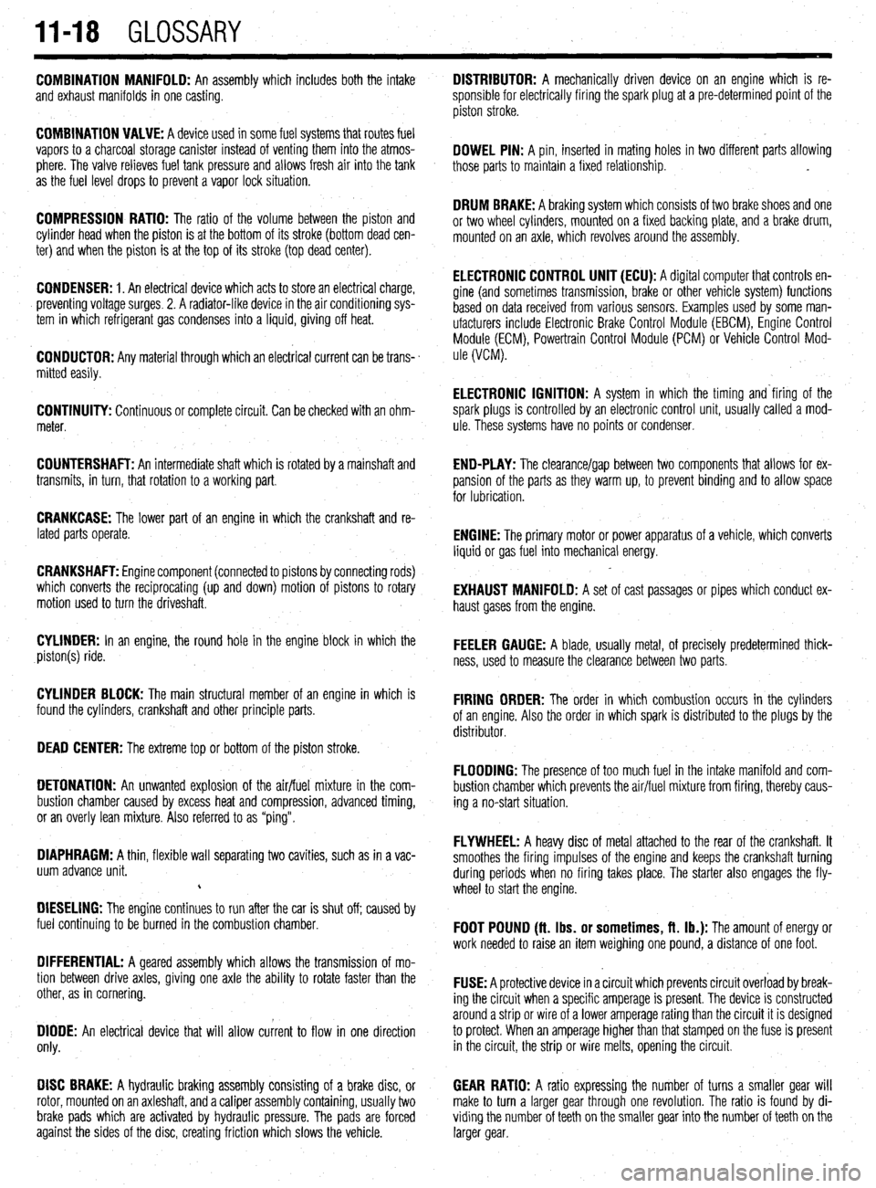
11-18 GLOSSARY
COMBINATION MANIFOLD: An assembly which includes both the intake
and exhaust manifolds in one casting.
COMBINATION VALVE: A device used in some fuel systems that routes fuel
vapors to a charcoal storage canister instead of venting them into the atmos-
phere. The valve relieves fuel tank pressure
and allows fresh air into the tank
as the fuel level drops to prevent a vapor lock situation.
COMPRESSION RATIO: The ratio of the volume between the piston and
cylinder head when the piston is at the bottom of its stroke (bottom dead cen-
ter) and when the piston is at the top of its stroke (top dead center).
CONDENSER: 1. An electrical device which acts to store an electrical charge,
preventing voltage surges. 2. A radiator-like device in the air conditioning sys-
tem in which refrigerant gas condenses into a liquid, giving off heat.
CONDUCTOR: Any material through which an electrical current can be trans-
mitted easily.
CONTINUITY: Continuous or complete circuit. Can be checked with an ohm-
meter.
COUNTERSHAFT: An intermediate shaft which is rotated by a mainshaft and
transmits, in turn, that rotation to a working part.
CRANKCASE: The lower part of an engine in which the crankshaft and re-
lated parts operate.
CRANKSHAFT: Engine component (connected to pistons by connecting rods)
which converts the reciprocating (up and down) motion of pistons to rotary
motion used to turn the driveshaft.
CYLINDER: In an engine, the round hole in the engine block in which the
piston(s) ride.
CYLINDER BLOCK: The main structural member of an engine in which is
found the cylinders, crankshaft and other principle parts.
DEAD CENTER: The extreme top or bottom of the piston stroke.
DETONATION: An unwanted explosion of the air/fuel mixture in the com-
bustion chamber caused by excess heat and compression, advanced timing,
or an overly lean mixture. Also referred to as “ping”.
DIAPHRAGM: A thin, flexible wall separating two cavities, such as in a vac-
uum advance unit.
c
DIESELING: The engine continues to run after the car is shut off; caused by
fuel continuing to be burned in the combustion chamber.
DIFFERENTIAL: A geared assembly which allows the transmission of mo-
tion between drive axles, giving one axle the ability to rotate faster than the
other, as in cornering.
DIODE: An electrical device that will allow current to flow in one direction
only.
DISC BRAKE: A hydraulic braking assembly consisting of a brake disc, or
rotor, mounted on an axleshaft, anda caliper assembly containing, usually two GEAR RATIO: A ratio expressing the number of turns a smaller gear will
make to turn a larger gear through one revolution. The ratio is found by di-
brake pads which are activated by hydraulic pressure. The pads are forced viding the number of teeth on the smaller gear into the number of teeth on the
against the sides of the disc, creating friction which slows the vehicle. larger gear. DISTRIBUTOR: A mechanically driven device on an engine which is re-
sponsible for electrically firing the spark plug at a pre-determined point of the
piston stroke.
DOWEL PIN: A pin, inserted in mating holes in two different parts allowing
those parts to maintain a fixed relationship. .
DRUM BRAKE: A braking system which consists of two brake shoes and one
or two wheel cylinders, mounted on a fixed backing plate, and a brake drum,
mounted on an axle, which revolves around the assembly.
ELECTRONIC CONTROL UNIT (ECU): A diqital computer that controls en-
gine (and sometimes transmission‘, brake or other vehicle system) functions
based on data received from various sensors. Examples used by some man-
ufacturers include Electronic Brake Control Module (EBCM), Engine Control
Module (ECM), Powertrain Control Module (PCM) or Vehicle Control Mod-
ule (VCM).
ELECTRONIC IGNITION: A system in which the timing and‘firing of the
spark plugs is controlled by an electronic control unit, usually called a mod-
ule. These systems have no points or condenser,
END-PLAY: The clearance/gap between two components that allows for ex-
pansion of the parts as they warm up, to prevent binding and to allow space
for lubrication.
ENGINE: The primary motor or power apparatus of a vehicle, which converts
liquid or gas fuel into mechanical energy.
EXHAUST MANIFOLD: A set of cast passages or pipes which conduct ex-
haust gases from the engine.
FEELER GAUGE: A blade, usually metal, of precisely predetermined thick-
ness, used to measure the clearance between two parts.
FIRING ORDER: The order in which combustion occurs in the cylinders
of an engine. Also the order in which spark is distributed to the plugs by the
distributor.
FLOODING: The presence of too much fuel in the intake manifold and com-
bustion chamber which prevents the air/fuel mixture from firing, thereby caus-
ing a no-start situation.
FLYWHEEL: A heavy disc of metal attached to the rear of the crankshaft. It
smoothes the firing impulses of the engine and keeps the crankshaft turning
during periods when no firing takes place. The starter also engages the fly-
wheel to start the engine.
FOOT POUND (ft. Ibs. or sometimes, ft. lb.): The amount of energy or
work needed to raise an item weighing one pound, a distance of one foot.
FUSE: A protective device in a circuit which prevents circuit overload by break-
ing the circuit when a specific amperage is present. The device is constructed
around a strip or wire of a lower amperage rating than the circuit it is designed
to protect. When an amperage higher than that stamped on the fuse is present
in the circuit, the strip or wire melts, opening the circuit.