1900 MITSUBISHI DIAMANTE Rear shock
[x] Cancel search: Rear shockPage 356 of 408
‘I
9-20 ,BRAKES
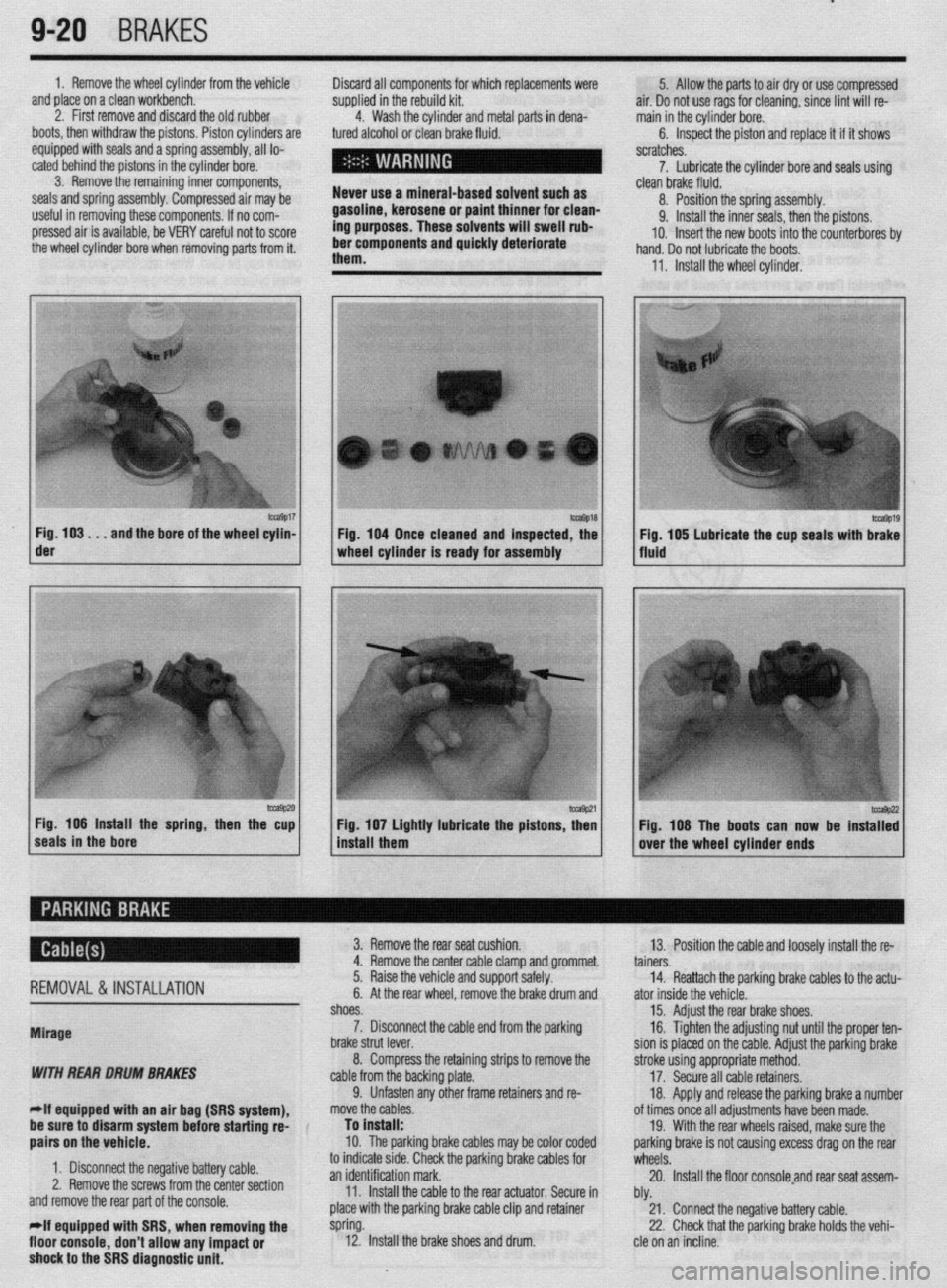
1. Remove the wheel cylinder from the vehicle
and place on a clean workbench.
2. First remove and discard the old rubber
boots, then withdraw the pistons. Piston cylinders are
equipped with seals and a spring assembly, all lo-
cated behind the pistons in the cylinder bore.
3. Remove the remaining inner components,
seals and spring assembly. Compressed air may be
useful in removing these components. If no com-
pressed air is available, be VERY careful not to score
the wheel cylinder bore when removing parts from it. Discard all components for which replacements were
supplied in the rebuild kit.
4. Wash the cylinder and metal parts in dena-
tured alcohol or clean brake fluid.
Never use a mineral-based solvent such as
gasoline, kerosene or paint thinner for clean-
ing purposes. These solvents will swell rub-
ber components and quickly deteriorate
them. 5. Allow the parts to air dry or use compressed
air. Do not use rags for cleaning, since lint will re-
main in the cylinder bore.
6. Inspect the piston and replace it if it shows
scratches.
7. Lubricate the cylinder bore and seals using
- clean brake fluid.
8. Position the spring assembly.
9. Install the inner seals, then the pistons.
IO. Insert the new boots into the counterbores bv
hand. Do not lubricate the boots,
11, Install the wheel cylinder,
m9017 Fig. 103. . .
and the bore of the wheel cylin- der
-9P20 Fig. 106 Install the spring, then the cup
seals in the bore 1 Fig. 104 Once cleaned and inspected, the
1 wheel cylinder Is ready for assembly
1 install them Fig 107 Lightly lubricate the pistons z
’ Fig. 108 The boots can now be instaT:
over the wheel cylinder ends
REMOVAL& INSTALLATION
Mirage
WITH REAR DRUM BRAKES
-If equipped witti an air bag (SRS system), 3. Remove the rear seat cushion.
13. Position the cable and loosely install the re-
4. Remove the center cable clamp and grommet.
tainers.
5. Raise the vehicle and support safely.
14. Reattach the parking brake cables to the actu-
6. At the rear wheel, remove the brake drum and
ator inside the vehicle.
shoes.
15. Adjust the rear brake shoes.
7. Disconnect the cable end from the parking
16. Tighten the adjusting nut until the proper ten-
brake strut lever.
sion is placed on the cable. Adjust the parking brake
8. Compress the retaining strips to remove the
stroke using appropriate method.
cable from the backing plate.
17. Secure all cable retainers,
9. Unfasten any other frame retainers and re-
18. Apply and release the parking brake a number
move the cables.
of times once all adjustments have been made.
be sure to disarm system
befok starting rd-
aairs on the vehicle. To install:
10. The parkinq brake cables mav be color coded 19. With the rear wheels raised, make sure the
oarkino brake is not causina excess draa on the rear
1. Disconnect the negative battery cable.
2. Remove the screws from the center section
and remove the rear part of the console.
*If equipped with SRS, when removing the
floor console,
don’t allow any impact or
shock to the SRS diagnostic unit. to indicate stde. Check the parking brake cables for
wheels: .A
an identification mark.
20. Install the floor consoleand rear seat assem-
11. Install the cable to the rear actuator. Secure in
bly.
place with the parking brake cable clip and retainer
21. Connect the negative battery cable.
spring.
22. Check that the parking brake holds the vehi-
12. Install the brake shoes and drum.
cle on an incline.
Page 357 of 408
BRAKES 9-21
WITH REAR DISC BRAKES
*If equipped with an air bag (SRS system),
be sure to disarm the system before starting
repairs on the vehicle.
1. Disconnect the negative battery cable.
2. Remove the screws from the center section
and remove the rear part of the console.
*If equipped with SRS, when removing the
floor console, don’t allow any impact or
shock to the SRS diagnostic unit.
3. Remove the rear seat cushion.
4. Loosen the cable adjusting nut and discon-
nect the rear brake cables from the actuator.
5. Remove the center cable clamp and grommet.
6. Raise the vehicle and support safely.
7. Remove the parking brake cable clip and re-
tainer spring.
8. Disconnect the cable end from the parking
brake assembly.
9. Unfasten any remaining frame retainers and
remove the cables from the vehicle.
To install: IO. The parking brake cables may be color coded
to indicate side. Check the parking brake cables for
an identification mark.
11. Install the cable to the rear actuator. Secure in
place with the parking brake cable clip and retainer
spring.
12. Position the cable and loosely install the re-
tainers.
13. Reattach the parking brake cables to the actu-
ator inside the vehicle.
14. Tighten the adjusting nut until the proper ten-
sion is placed on the cable. Adjust the parking brake
. stroke using appropriate method.
15. Secure all cable retainers.
16. Apply and release the parking brake a number
of times once all adjustments have been made.
17. With the rear wheels raised, make sure the
parking brake is not causing excess drag on the rear
wheels.
18. Install the floor console and rear seat assem-
bly.
19. Connect the negative battery cable.
20. Check console electrical components for
proper operation.
21. Road test the vehicle and check for proper
brake operation.
22. Check that the parking brake holds the vehi-
cle on an incline.
1990-93 Galant
WITH REAR DRUM BRAKES
1. Disconnect the negative battery cable.
2. Remove the center console as follows:
a. Remove both side cover panels.
b. Remove the shifter knob on manual
transaxle models. Remove the spacer trim piece
on automatic transaxle models.
c. Remove the switch panel/box and remove
the two screws beneath the panel/box.
d. Remove the radio trim panel.
e. Remove the radio and tape player.
f. Remove the console inner panel and re-
move the two screws for beneath the panel.
g. Remove the remaining screws from the
sides of the console. h. Remove the console assembly from the ve-
hicle.
3. While pressing downward on the front of the
rear seat cushion, release the locking levers and re-
move the seat cushion.
4. Loosen the cable adjustment at the cable
equalizer.
5. Remove the center cable clamp and grommet.
6. Raise the vehicle and support safely.
7. At the rear wheel, remove the brake drum and
shoes.
8. Disconnect the cable end from the parking
brake strut lever.
9. Remove the snapring securing the cable to
the backing plate.
IO. Unfasten any other frame retainers and re-
move the cables.
To install:
*The parking brake cables may be color
coded to indicate side. Check the parking
brake cables for an identification mark.
11. Install the cable to the rear actuator. Secure in
place with the parking brake cable clip and snapring.
12. Install the brake shoes and drum.
13. Position the cable and loosely install the re-
tainers
14. Reattach the parking brake cables to the actu-
ator inside the vehicle. Tighten the adjusting nut until
the proper tension is placed on the cable. Adjust the
parking brake stroke using appropriate method.
15. Secure all cable retainers.
16. Apply and release the parking brake a number
of times once all adjustments have been made.
17. Adjust the rear brakes and parking brake ca-
bles.
18. Check the rear wheels to confirm that the rear
brakes are not dragging.
19. Install the center console and rear seat cush-
ion.
20. Connect the negative battery cable.
21. Check console electrical components for
proper operation.
22. Check that the parking brake holds the vehi-
cle on an incline.
WITH REAR DISC BRAKES
1. Disconnect the negative battery cable.
2. Remove the center console as follows:
a. Remove both side cover panels.
b. Remove the shifter knob on manual
transaxle models. Remove the spacer trim piece
on automatic transaxle models.
c. Remove the switch panel/box and remove
the two screws beneath the panel/box.
d. Remove the radio trim panel.
e. Remove the radio and tape player.
f. Remove the console inner panel and re-
move the two screws from beneath the panel.
g. Remove the remaining screws from the
sides of the console.
h. Remove the console assembly from the ve-
hicle.
3. While pressing downward on the front of the
rear seat cushion, release the locking levers and re-
move the seat cushion.
4. Loosen the cable adjusting nut and discon-
nect the rear brake cables from the actuator.
5. Remove the center cable clamp and grommet.
6. Raise the vehicle and support it safely. 7. At the rear caliper assembly, remove the
parking brake cable clip and retainer spring.
8. Disconnect the cable end from the caliper.
9. Unfasten any remaining frame retainers and
remove the cables from the vehicle.
To install:
*The parking brake cables may be color
coded to indicate side. Check the parking
brake cables for an identification mark.
IO. Connect the cable to the actuator at the brake
caliper. Secure in place with the parking brake cable
clip and retainer spring.
11. Position the cable and loosely install the re-
tainers.
12. Reattach the parking brake cables to the actu-
ator inside the vehicle. Tighten the adjusting nut until
the proper tension is placed on the cable.
13. Adjust the parking brake stroke using appro-
priate method.
14. Secure all cable retainers.
15. Apply and release the parking brake a number
of times once all adjustments have been made.
16. With the rear wheels raised, make sure the
parking brake is not causing excess drag on the rear
wheels.
17. Install the floor console assembly and rear
seat cushion.
18. Connect the negative battery cable.
19. Check console electrical components for
proper operation.
20. Road test the vehicle and check for proper
brake operation.
21. Check that the parking brake holds the vehi-
cle on an incline.
1994-00 Galant
WITH REAR DRUM BRAKES
1. Disconnect the negative battery cable.
The SRS control unit is mounted beneath the
center console. Use care when working with
the center console assembly not to impact or
shock the control unit.
2. Remove the center floor console assembly as
follows:
a. Remove the shifter knob on models
equipped with a manual transaxle.
b. Remove the shifter trim panel.
c. Remove the center instrument panel.
d. Remove the panel box from the console
assembly.
e. Remove the two screws from the center of
the console.
f. Remove the four side panel screws and re-
move the console from the vehicle.
3. Loosen the cable adjuster nut, then remove
the parking brake cable by pulling it from the passen-
ger compartment.
4. Raise the vehicle and support safely.
5. At the rear wheel, remove the brake drum and
shoes.
6. Disconnect the cable end from the parking
brake strut lever. Compress the retaining strips to re-
move the cable from the backing plate.
Page 358 of 408
--7 9-22
BRAKES
7. Unfasten any other frame retainers and re-
move the cables.
To install: 8. Install the cable to the rear actuator. Secure in ’
place with the parking brake cable clip and retainer
spring. b. Remove the shifter trim panel.
c. Remove the center instrument panel.
d. Remove the panel box from the console
assembly.
e. Remove the two screws from the center of
the console.
9. Install the brake shoes and drum.
10. Position the cable and loosely install the re-
tainers.
Il. Reattach the parking brake cables to the actu-
ator inside the vehicle.
12. Tighten the adjusting nut until the proper ten-
sion is placed on the cable.
13. Adjust the parking brake stroke using appro-
priate method.
14. Secure all cable retainers. Apply and release
the parking brake a number of times once all adjust-
ments have been made.
15. Assemble the interior components which
were removed.
16. Adjust the rear brakes and parking brake ca-
bles.
17. Connect the negative battery cable.
18. Check the rear wheels to confirm that the rear
brakes are not dragging.
19. Check that the parking brake holds the vehi-
cle on an incline.
WITH REAR DISC BRAKES
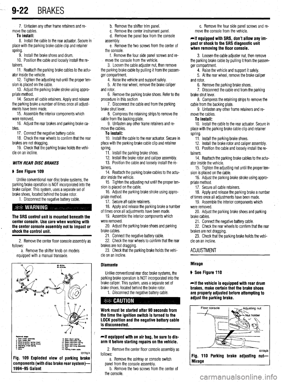
) See Figure 109
Unlike conventional rear disc brake systems, the
parking brake operation is NOT incorporated into the
brake caliper. This system, uses a separate set of
brake shoes, located behind the brake rotor.
1. Disconnect the negative battery cable.
The SRS control unit is mounted beneath the
center console. Use care when working with
17. Secure all cable retainers.
18. Apply and release the parking brake a number
of times once all adjustments have been made.
19. Assemble the interior components which
were removed.
l the center console assembly not to impact or 20. Adjust the parking brake shoes and parking shock the control unit. brake cables.
2. Remove the center floor console assembly as
follows:
a. Remove the shifter knob on models
equipped with a manual transaxle. 21. Connect the negative battery cable.
22. Check the rear wheels to confirm that the rear
brakes are not dragging.
23. Check that the parking brake holds the vehi-
cle on an incline.
8. Stnd return aring
0 Shwhdd-downcup
10. shna hchd-dPwn SpnnQ
11. Shm hold-dcwn pm
12. shoe and lllllnp us*mbly
13.
14 cap
PwkilvJbnko~
93159g24 Fig. 109 Exploded view of parking brake
components (with disc brake rear system)-
1994-95 Galant
f. Remove the four side panel screws and re-
d move the console from the vehicle.
3. Loosen the cable adjuster nut, then remove
the parking brake cable by pulling it from the passen-
ger compartment.
4. Raise the vehicle and support safely.
5. At the rear wheel, remove the brake caliper
and rotor.
6. Remove the parking brake shoes. Refer to the
procedure in this section.
7. Disconnect the cable end from the parking
brake strut lever.
8. Compress the retaining strips to remove the
cable from the backing plate.
9. Unfasten any other frame retainers and re-
move the cables.
To install: IO. Install the cable to the rear actuator. Secure in
place with the parking brake cable clip and retainer
spring.
Il. Install the parking brake shoes.
12. Install the brake rotor and caliper assembly.
13. Position the cable and loosely install the re-
tainers.
14. Reattach the parking brake cables to the actu-
ator inside the vehicle.
15. Tighten the adjusting nut until the proper ten-
sion is placed on the cable.
16. Adjust the parking brake stroke using appro-
priate method.
Diamante
Unlike conventional rear disc brake systems, the
parking brake operation is NOT incorporated into the
brake caliper. This system, uses a separate set of
brake shoes, located behind the brake rotor.
1. Disconnect the negative battery cable.
Work must be started after 90 seconds from
the time the ignition switch is turned to the
LOCK position and the negative battery cable
is disconnected.
*If equipped with an air bag, be sure to dis-
arm it before starting repairs on the vehicle.
2. Remove the center floor console assembly as
follows:
a. Remove the ashtray or console switch
panel from the console assembly.
b. Remove the two screws from the center of
the console. c. Remove the four side panel screws and re-
move the console from the vehicle.
*If equipped with SRS, don’t allow any im-
pact or shock to the SRS diagnostic unit
when removing the floor console.
3. Loosen the cable adjuster nut, then remove
the parking brake cable by pulling it from the passen-
ger compartment.
4. Raise the vehicle and support it safely.
5. At the rear wheel, remove the brake caliper
and rotor.
6. Remove the parking brake shoes.
7. Disconnect the cable end from the parking
brake strut lever.
8. Compress the retaining strips to remove the
cable from the backing plate.
9. Unfasten any other frame retainers and re-
move the cables.
To install: 10. Install the cable to the rear actuator. Secure in
place with the parking brake cable clip and retainer
spring.
11. Install the parking brake shoes.
12. Install the brake rotor and caliper assembly.
13. Position the cable and loosely install the re-
tainers.
14. Reattach the parking brake cables to the actu-
ator inside the vehicle.
15. Tighten the adjusting nut until the proper ten-
sion is placed on the cable.
16. Adjust the parking brake stroke using appro-
priate method.
17. Secure all cable retainers.
18. Apply and release the parking brake a number
of times once all adjustments have been made.
19. Assemble the interior components which
were removed.
20. Adjust the parking brake shoes and parking
brake cables.
21. Connect the negative battery cable.
22. Check the rear wheels to confirm that the rear
brakes are not dragging.
23. Check that the parking brake holds the vehi-
cle on an incline.
ADJUSTMENT
Mirage
) See Figure 110
*If the vehicle is equipped with rear drum
brakes, make certain that the brake shoes
are properly adjusted before attempting to
adjust the parking brake.
Floor console
93159936 Fig. 110 Parking brake adjusting nut-
Mirage
Page 394 of 408
IJront Wheel or Wheel Bearing Loose
All Wheel and Four Wheel Drive Vehicles a. Torque lug nuts and axle nuts to specification and recheck for looseness.
b. Wheel bearing worn or damaged. Replace wheel bearing.
Front Wheel Drive Vehicles
a. Torque lug nuts and axle nuts to specification and recheck for looseness.
b. Wheel bearing worn or damaged. Replace wheel bearing.
Rear Wheel Drive Vehicles a. Wheel bearing out of adjustment. Adjust wheel bearing to specification; if still loose,
replace.
b. Torque lug nuts to specification and recheck for looseness.
c. Wheel bearing worn or damaged. Replace wheel bearing.
2. Rear Wheel or Wheel Bearing Loose
All Wheel and Four Wheel Drive Vehicles a. Torque lug nuts and axle nuts to specification and recheck for looseness.
b. Wheel bearing worn or damaged. Replace wheel bearing.
Front Wheel Drive Vehicles a. Wheel bearing out of adjustment. Adjust wheel bearing to specification; if still loose,
replace.
b. Torque lug nuts to specification and recheck for looseness.
c. Wheel bearing worn or damaged. Replace wheel bearing.
Rear Wheel Drive Vehicles a. Torque lug nuts and to specification and recheck for looseness.
b. Wheel bearing worn or damaged. Replace wheel bearing.
11-12 TROUBLESHOOTING
8. Brake pedal goes to floor when pressed and will not pump up
a. Check the brake hydraulic fluid level and inspect the fluid lines and seals for leakage.
Repair or replace leaking components, then bleed and flush the brake system using
fresh brake fluid that meets the manufacturer’s recommended standards.
b. Check the brake fluid level. Inspect the brake fluid level and brake hydraulic seals. If
the fluid level is ok, and the brake hydraulic system is free of hydraulic leaks, replace
the brake master cylinder, then bleed and flush the brake system using fresh brake
fluid that meets the manufacturer’s recommended standards.
9. Brakes produce a burning odor
a. Check for a seizing brake hydraulic component such as a brake caliper. Check the
caliper piston for surface damage such as rust, and measure for out-of-round wear
and caliper-to-piston clearance. Overhaul or replace failed parts and flush the brake
system.
b. Check for an internally restricted flexible brake hydraulic hose. Replace the hose and
flush the brake system.
c. Check the parking brake release mechanism, seized linkage or cable, and repair as
necessary. BRAKE PERFORMANCE TROU5LESHOOTINc; HIIVTS Brake vibrations or pulsation can often be diagnosed on a safe and careful test drive.
A brake vibration which is felt through the brake pedal while braking, but not felt in the
steering wheel, is most likely caused by brake surface variations in the rear brakes. If
both the brake pedal and steering wheel vibrate during braking, a surface variation in the
front brakes, or both front and rear brakes, is very likely.
A brake pedal that pumps up with repeated use can be caused by air in the brake hy-
draulic system or, if the vehicle is equipped with rear drum brakes, the brake adjusters
may be seized or out of adjustment. A quick test for brake adjustment on vehicles with
rear drum brakes is to pump the brake pedal several times with the vehicle’s engine not
running and the parking brake released. Pump the brake pedal several times and con-
tinue to apply pressure to the brake pedal. With pressure being applied to the brake
pedal, engage the parking brake. Release the brake pedal and quickly press the brake
pedal again. If the brake pedal pumped up, the rear brakes are in need of adjustment. Do
not compensate for the rear brake adjustment by adjusting the parking brake, this will
cause premature brake lining wear.
To test a vacuum brake booster, pump the brake pedal several times with the vehicle’s
engine off. Apply pressure to the brake pedal and then start the engine. The brake pedal
should move downward about one inch (25mm).
1. Tires worn on inside tread
a. Check alignment for a toed-out condition. Check and set tire pressures and properly
adjust the toe.
b. Check for worn, damaged or defective suspension components. Replace defective
parts and adjust the alignment.
2. Tires worn on outside tread e
a. Check alignment for a toed-in condition. Check and set tire pressures and properly
adjust the toe.
b. Check for worn, damaged or defective suspension components. Replace defective
parts and adjust the alignment.
3. Tires worn unevenly
a. Check the tire pressure and tire balance. Replace worn or defective tires and check the
.
alignment; adjust if necessary. b. Check for worn shock absorbers. Replaced failed components, worn or defective tires
and check the alignment; adjust if necessary.
c. Check the alignment settings. Check and set tire pressures and properly adjust the
alignment to specification.
d. Check for worn, damaged or defective suspension components. Replace defective
parts and adjust the alignment to specification,
1. Excessive play in steering wheel
a. Check the steering gear free-play adjustment and properly adjust to remove excessive
play.
b. Check the steering linkage for worn, damaged or defective parts. Replace failed com-
ponents and perform a front end alignment.
c. Check for a worn, damaged, or defective steering box, replace the steering gear and
check the front end alignment.
2. Steering wheel shakes at cruising speeds
a. Check for a bent front wheel. Replace a damaged wheel and check the tire for possible
internal damage.
b. Check for an unevenly worn front tire. Replace the tire, adjust tire pressure and bal-
ance.
c. Check the front tires for hidden internal damage. Tires which have encountered large
pot holes or suffered other hard blows may have sustained internal damage and
should be replaced immediately.
d. Check the front tires for an out-of-balance condition. Remove, spin balance and rein-
stall. Torque all the wheel bolts or lug nuts to the recommended specification.
e. Check for a loose wheel bearing. If possible, adjust the bearing, or replace the bearing
if it is a non-adjustable bearing.
3. Steering wheel shakes when braking
a. Refer to section 3-A, condition number 1.
4. Steering wheel becomes stiff when turned
a. Check the steering wheel free-play adjustment and reset as needed.
b. Check for a damaged steering gear assembly. Replace the steering gear and perform a
front end alignment.
c. Check for damaged or seized suspension components. Replace defective components
and perform a front end alignment.
1. Vehicle pulls to one side
a. Tire pressure uneven. Adjust tire pressure to recommended settings.
b. Tires worn unevenly. Replace tires and check alignment settings.
c. Alignment out of specification. Align front end and check thrust angle.
d. Check for a dragging brake and repair or replace as necessary.
2. Vehicle is very bouncy over bumps
a. Check for worn or leaking shock absorbers or strut assemblies and replace as neces-
sary.
b. Check for seized shock absorbers or strut assemblies and replace as necessary.
Page 395 of 408
TROUBLESHOOTING 11-13
NOTE: When one shock fails, ft is recommended to replace front or rear
units as pairs.
3. Vehicle leans excessively in turns
a. Check for worn or leaking shock absorbers or strut assemblies and replace as neces-
sary.
b. Check for missing, damaged, or worn stabilizer links or bushings, and replace or in-
stall as necessary.
4. Vehicle ride quality seems excessively ha&h
a. Check for seized shock absorbers or strut assemblies and replace as necessary.
b. Check for excessively high tire pressures and adjust pressures to vehicle recommen-
dations.
5. Vehicle seems low or leans to one side
a. Check for a damaged, broken or weak spring. Replace defective parts and check for a
needed alignment.
b. Check for seized shock absorbers or strut assemblies and replace as necessary.
c. Check for worn or leaking shock absorbers or strut assemblies and replace as neces-
sary.
Noises 1. Vehicle makes a clicking noises when driven
a. Check the noise to see if it varies with road speed. Verify if the noise is present when
coasting or with steering or throttle input. If the clicking noise frequency changes with
road speed and is not affected by steering or throttle input, check the tire treads for a
stone, piece of glass, nail or another hard object imbedded into the tire or tire tread.
Stones rarely cause a tire puncture and are easily removed. Other objects may create
an air leak when removed. Consider having these objects removed immediately at a
facility equipped to repair tire punctures.
b. If the clicking noise varies with throttle input and steering, check for a worn Constant
Velocity (CV-joint) joint, universal (U- joint) or flex joint.
2. Vehicle makes a clunking or knocking noise over bumps
a. A clunking noise over bumps is most often caused by excessive movement or clear-
ance in a suspension component. Check the suspension for soft, cracked, damaged or
worn bushings. Replace the bushings and check the vehicle’s alignment.
b. Check for loose suspension mounting bolts. Check the tightness on subframe bolts,
pivot bolts and suspension mounting bolts, and torque to specification.
c. Check the vehicle for a loose wheel bearing. Some wheel bearings can be adjusted for
looseness, while others must be replaced if loose. Adjust or replace the bearings as
recommended by the manufacturer.
d. Check the door latch adjustment. If the door is slightly loose, or the latch adjustment
is not centered, the door assembly may create noises over bumps and rough surfaces.
Properly adjust the door latches to secure the door. 3. Vehicle makes a low pitched rumbling noise when driven
a. A low pitched rumbling noise is usually caused by a drive train related bearing and is
most often associated with a wheel bearing which has been damaged or worn. The
damage can be caused by excessive brake temperatures or physical contact with a pot
hole or curb. Sometimes the noise will vary when turning. Left hand turns increase the
load on the vehicle’s right side, and right turns load the left side. A failed front wheel
bearing may also cause a slight steering wheel vibration when turning. A bearing
which exhibits noise must be replaced.
b. Check the tire condition and balance. An internally damaged tire may cause failure
symptoms similar to failed suspension parts. For diagnostic purposes, try a known
good set of tires and replace defective tires.
4. Vehicle makes a squeaking noise over bumps
a. Check the vehicle’s ball joints for wear, damaged or leaking boots. Replace a ball joint
if it is loose, the boot is damaged and leaking, or the ball joint is binding. When re-
placing suspension parts, check the vehicle for alignment.
b. Check for seized or deteriorated bushings. Replace bushings that are worn or dam-
aged and check the vehicle for alignment.
c. Check for the presence of sway bar or stabilizer bar bushings which wrap around the
bar. Inspect the condition of the bushings and replace if worn or damaged. Remove
the bushing bracket and apply a thin layer of suspension grease to the area where the
bushings wrap around the bar and reinstall the bushing brackets. ~
5. Vehicle vibrates when driven
a. Check the road surface. Roads which have rough or uneven surfaces may cause un-
usual vi brations.
b. Check the tire condition and balance. An internally damaged tire may cause failure
symptoms similar to failed suspension parts. For diagnostic purposes, try a known
good set of tires and replace defective tires immediately.
c. Check for a worn Constant Velocity (CV-joint) joint, universal (U- joint) or flex joint
and replace if loose, damaged or binding.
d. Check for a loose, bent, or out-of-balance axle or drive shaft. Replace damaged or
failed components.
NOTE: Diagnosing failures related to wheels, tires, steering and the sus-
pension system can often times be accomplished with a careful and thor-
ough test drive. Bearing noises are isolated by noting whether the noises
or symptoms vary when turning left or right, or occur while driving a
straight line. During a teft hand turn, the vehicle’s weight shifts to the
right, placing more force on the right side bearings, such that if a right side
wheel bearing is worn or damaged, the noise or vibration should increase
during light-to-heavy acceleration. Conversely, on right hand turns, the ve-
hicle tends to lean to the left, loading the left side bearings.
Knocking noises in the suspension when the vehicle is driven over rough roads, rail-
road tracks and speed bumps indicate worn suspension components such as bushings,
ball joints or tie rod ends, or a worn steering system.
1. One headlight only works on high or low beam
a. Check for battery voltage at headlight electrical connector. If battery voltage is present,
replace the headlight assembly or bulb if available separately. If battery voltage is not
present, refer to the headlight wiring diagram to troubleshoot.
2. Headlight does not work on high or low beam
a. Check for battery voltage and ground at headlight electrical connector. If battery volt-
age is present, check the headlight connector ground terminal for a proper ground. If
battery voltage and ground are present at the headlight connector, replace the head-
light assembly or bulb if available separately. If battery voltage or ground is not pre-
sent, refer to the headlight wiring diagram to troubleshoot.
b. Check the headlight switch operation. Replace the switch if the switch is defective or
ooerates intermittentlv. 1. Tail light, running light or side marker light inoperative
a. Check for battery voltage and ground at light’s electrical connector. If battery voltage is
present, check the bulb socket and electrical connector ground terminal for a proper
ground. If battery voltage and ground are present at the light connector, but not in the
socket, clean the socket and the ground terminal connector. If battery voltage and
ground are present in the bulb socket, replace the bulb. If battery voltage or ground is
not present, refer to the wiring diagram to troubleshoot for an open circuit.
b. Check the light switch operation and replace if necessary.
2. Tall light, running light or side marker light works intermittently
a. Check the bulb for a damaged filament, and replace if damaged.
b. Check the bulb and bulb socket for corrosion, and clean or replace the bulb and
socket.
w 3. Headlight(s) very dim
a. Check for battery voltage and ground at headlight electrical connector. If battery volt-
age is present, trace the ground circuit for the headlamp electrical connector, then
clean and repair as necessary. If the voltage at the headlight electrical connector is
significantly less than the voltage at the battery, refer to the headlight wiring diagram
to troubleshoot and locate the voltage drop. c. Check for loose, damaged or corroded wires and electrical terminals, and repair as
necessary.
d. Check the light switch operation and replace if necessary.
3. Tail light, running light or side marker light very dim
a. Check the bulb and bulb socket for corrosion and clean or replace the bulb and
socket.
Page 407 of 408
MASTER INDEX 11-25 -
REAROUTPUTSHAFTSEAL 7-14
TESTING 6-5
REMOVAL & INSTALLATION 7-14
' THERMOSTAT 3-7
REAR SUSPENSION 8-18 REMOVAL & INSTALLATION 3-7
REAR WINDOW WIPER SWITCH 6-19 THROTTLE BODY 5-3
REMOVAL&INSTALLATION 6-19 REMOVAL & INSTALLATION 5-3
REARDRlVEAXLE(AWDGALANTONLY) l-38
THROTTLEPOSITIONSENSOR 4-13
DRAIN &REFILL 1-38
OPERATION 4-13
FLUIDRECOMMENDATIONS 1-38 , REMOVAL&INSTALLATION 4-13
LEVELCHECK l-38
TESTING 4-13
REGULATOR 2-10 TIMING COVERAND BELT 3-36
REMOVAL&INSTALLATION 2-10
INSPECTION 3-48
RELIEVING FUELSYSTEM PRESSURE 5-3 REMOVAL & INSTALLATION 3-36
ROCKERARM(VALVE)COVER 3-1
TIMING BELTS l-20
REMOVAL & INSTALLATION 3-1
INSPECTION I-20
ROCKER ARM/SHAFTS 3-4
TIRESANDWHEELS I-30
REMOVAL & INSTALLATION 3-4
CAREOFSPECIALWHEELS l-32
ROUTINE MAINTENANCE AND TUNE-UP 1-14 INFLATION & INSPECTION I-31
SEATS IO-IO
TIRE DESIGN I-31
REMOVAL&INSTALLATION IO-IO TIRE ROTATION I-30
SENDING UNITS 2-11
TIRESTORAGE I-31
SERIAL NUMBER IDENTIFICATION l-10
TONE (EXCITER) RING 9-29
SERVICING YOUR VEHICLE SAFELY I-4
REMOVAL & INSTALLATION 9-29
SHOCKABSORBERAND COILSPRING 8-8
TOOLS AND EQUIPMENT 1-2
OVERHAUL 8-9
TORQUE 1-7
REMOVAL&INSTALLATION 8-8 TORQUEANGLEMETERS l-9
SIGNAL AND MARKER LIGHTS 6-21
TORQUEWRENCHES l-7
REMOVAL & INSTALLATION 6-21
TOWING THE VEHICLE 1-44
SPARKPLUG WIRES 1-24
TRAINING ARM 8-24
REMOVAL&INSTALLATION 1-24
REMOVAL & INSTALLATION 8-24
TESTING 1-24
TRANSAXLEIDENTIFICATION I-10
SPARKPLUGS l-22
TRANSFER CASE ASSEMBLY 7-14
INSPECTION &GAPPING l-23
REMOVAL & INSTALLATION 7-14
REMOVAL&INSTALLATION 1-22
TRANSFER CASE 7-14
SPARKPLUGHEATRANGE 1-22
TRANSFERCASE(AWD GALANT ONLY) 1-38
SPEAKERS 6-14
DRAIN &REFILL 1-38
REMOVAL & INSTALLATION 6-14
FLUIDRECOMMENDATIONS 1-38
SPECIALTOOLS 1-4
LEVELCHECK 1-38
SPEED SENSORS 9-28
TRANSFERCASE(AWDGALANTONLY) I-10
REMOVAL & INSTALLATION 9-28
TROUBLESHOOTING ELECTRICALSYSTEMS 6-5
STANDARDANDMETRIC MEASUREMENTS l-9
OPEN CIRCUITS 6-5
STARTER 2-10
RESISTANCE 6-8
REMOVAL&INSTALLATION 2-11
SHORT CIRCUITS 6-6
TESTING 2-10
VOLTAGEDROP 6-6
STARTING SYSTEM 2-10
VOLTAGE 6-6
STEERING LINKAGE 8-30
TRUNK LID IO-3
REMOVAL &INSTALLATION 8-30
ALIGNMENT IO-3
STEERING WHEEL 8-27
REMOVAL & INSTALLATION IO-3
REMOVAL &INSTALLATION 8-27
TURBOCHARGER 3-17
STEERING 8-27
REMOVAL & INSTALLATION 3-17
STRUT AND COIL SPRING
8-21
UNDERSTANDING AND TROUBLESHOOTING ELECTRICAL
OVERHAUL 8-22
SYSTEMS 6-2
REMOVAL & INSTALLATION 8-21
UNDERSTANDINGTHEAUTOMATICTRANSAXLE 7-10
STUBAXLESHAFT,BEARlNG AND SEAL 7-15
REMOVAL & INSTALLATION 7-10
REMOVAL&INSTALLATION 7-15
UNDERSTANDINGTHECLUTCH 7-7
SWAY BAR 8-12
ADJUSTMENTS 7-8
REMOVAL 8, INSTALLATION 8-12
REMOVAL&INSTALLATION 7-7
SWAY BAR 8-25
UNDERSTANDINGTHE MANUALTRANSAXLE 7-2
REMOVAL&INSTALLATION 8-25
SHIFT LINKAGE 7-2
TAILGATE/HATCH HANDLE lo-19
UPPER BALLJOINT 8-9
REMOVAL &INSTALLATION lo-10
INSPECTION 8-9
TAILGATE IO-3
REMOVAL &INSTALLATION 8-9
ALIGNMENT IO-3 i'
UPPER CONTROLARM 8-10
REMOVAL & INSTALLATION IO-3
REMOVAL & INSTALLATION 8-10
TANKASSEMBLY 5-10
UPPER CONTROL ARMS 8-22
REMOVAL&INSTALLATION 5-10
REMOVAL & INSTALLATION 8-22
TEST EQUIPMENT 6-4
VACUUM DIAGRAMS 4-36
JUMPER WIRES 6-4
VALVE LASH 1-27
MULTIMETERS 6-5
ADJUSTMENT 1-27
TEST LIGHTS 6-4
VEHICLE IDENTIFICATION NUMBER I-10