1900 MITSUBISHI DIAMANTE steering
[x] Cancel search: steeringPage 375 of 408
BODYANDTRIM IO-7
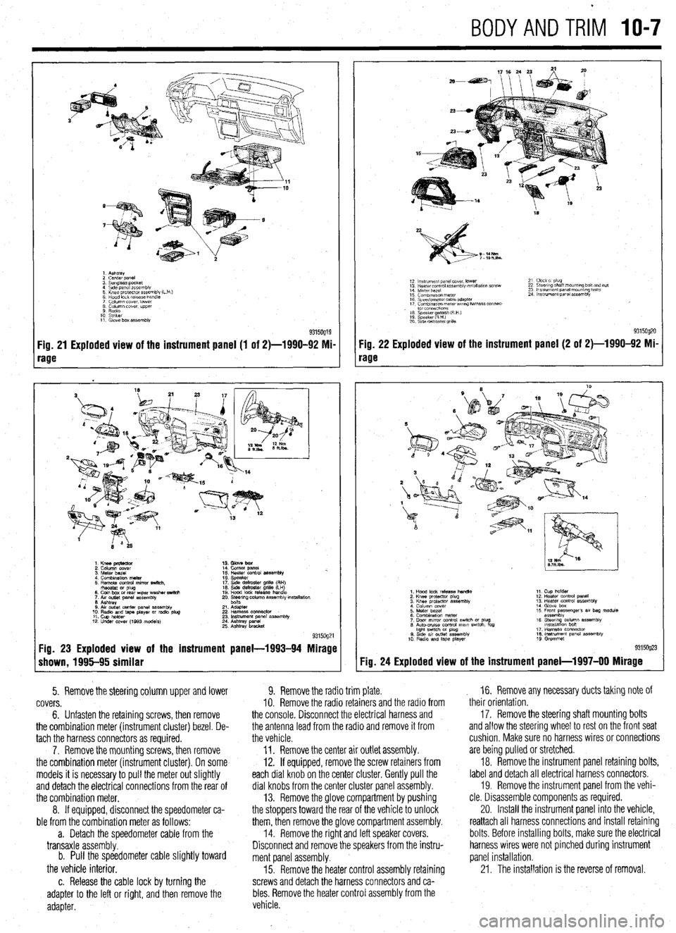
1. Ashtray
2 cenrer DaneI
3. Sunglass pocket
4 Side panel assembly
5 Knee protector assembly (L
6 Hood lock release handle
7 Column cover. lower
8 Column cover. upper
9 Radio
10 Striker
11. Glove box assembly
Fig. 21 Exploded view of the instrument panel (1 of 2)-1990-92 Mi-
rage
1. Knee pmtector
2. Column cover
3. Meter bezel
4. Combination meter
5. Remote control mirror switch.
rhsostat or plug
6. Coin box or rear wper washer switch
7. Aw outlet panel assembly
6. Ashtray
0. Air outlet center panel assembly
10. Radio and tape player or radio plug
11. Cup holder
12. Under COW (1993 models) 14. Comer panel
15. Heater control assembly %.
16. Speaker
17. Side defroster grille (RH)
16. Side defroster grille (LH)
19. Hood lock release handle
20. Ee$ng column assembly mstallation
21. Adapter
22 Harness oonnector
23. Instrument panel assembly
24. Ashtray panel
25. Ashtray bracket
9315og21 Fig. 23 Exploded view of the instrument panel-1993-94 Mirage
shown, 1995-95 similar
5. Remove the steering column upper and lower
covers.
6. Unfasten the retaining screws, then remove
the combination meter (instrument cluster) bezel. De-
tach the harness connectors as required.
7. Remove the mounting screws, then remove
the combination meter (instrument cluster). On some
models it is necessary to pull the meter out slightly
and detach the electrical connections from the rear of
the combination meter.
8. If equipped, disconnect the speedometer ca-
ble from the combination meter as follows:
a. Detach the speedometer cable from the
transaxle assembly.
b. Pull the speedometer cable slightly toward
the vehicle interior.
c. Release the cable lock by turning the
adapter to the left or right, and then remove the
adapter.
18
S-14Nm
7-lOh.lbs.
12 ln~v~rnent panel cover. lower
13 Hearer control assembly w,tallatlon screw
14 Meter bezel
15 Combination meter
16 Speedometer cable adapter
17 Comblnawn meterwr~ng harness connec-
. to1 co”“ectlo”s
16 Speaker amlsh (R H )
19 Speaker RHI e
20 S\de defroster grllla 21 Clock 01 plug
22 Steering shaft mount,ng bolt and nut
23 Ins!rument panel mounting bolts
24 Instrument panel assembly
9315og20 Fig. 22 Exploded view of the instrument panel (2 of 2)-1990-92 Mi-
rage
Fig. 24
1. Hood lock release handle
2. Knee protactor plug
3. Knee protector assembly
4 Column cover
5. Meter bezel
6. Combination meter
7. Door mrror control swich or plug
6. Auto-CNISO control mam swtch. fog
hght swtch M plug
0. Stde av outlet assembly
10 Radio and tape player 11. Cup holder
12. Heater control panel
13. Heater control assembly
14. Glove box
15 Front passenger’s 81, bag module
assembly
16. Steerq column assembly
lnstallatlon bon
17. Harness connector
16. Instrument panel assembly
19 Grommet
Exploded view of the instrument panel-l 997-00 Mirage
9. Remove the radio trim plate.
IO. Remove the radio retainers and the radio from
the console. Disconnect the electrical harness and
the antenna lead from the radio and remove it from
the vehicle.
11. Remove the center air outlet assembly.
12. If equipped, remove the screw retainers from
each dial knob on the center cluster. Gently pull the
dial knobs from the center cluster panel assembly.
13. Remove the glove compartment by pushing
the stoppers toward the rear of the vehicle to unlock
them, then remove the glove compartment assembly.
14. Remove the right and left speaker covers.
Disconnect and remove the speakers from the instru-
ment panel assembly.
15. Remove the heater control assembly retaining
screws and detach the harness connectors and ca-
bles. Remove the heater control assembly from the
vehicle. , 16. Remove any necessary ducts taking note of
their orientation,
17. Remove the steering shaft mounting bolts
and allow the steering wheel to rest on the front seat
cushion, Make sure no harness wires or connections
are being pulled or stretched.
18. Remove the instrument panel retaining bolts,
label and detach all electrical harness connectors.
19. Remove the instrument panel from the vehi-
cle. Disassemble components as required.
20. Install the instrument panel into the vehicle,
reattach all harness connections and install retaining
bolts. Before installing bolts, make sure the electrical
harness wires were not pinched during instrument
panel installation.
21. The installation is the reverse of removal.
Page 377 of 408
c BODYANDTRi'l IO-9
:: k% protector assembly
3. Knee protector support bracket
4. Column cover
5 Glove box striker
6 Glove box and glove box outer case
7 Under cover mstallatmn screw
8. Audio panel
9 Radio and tape player
10 Heater control panel
assembly 11 Cup holder
12. Speaker
13 Meter bezel
14 Combination meter
15 Speeoometer cable adapter
16 %&rrng column assembly rnstallatioh
17 Harness connector
18. Glove box kght swatch
19. Instrument panel assembly
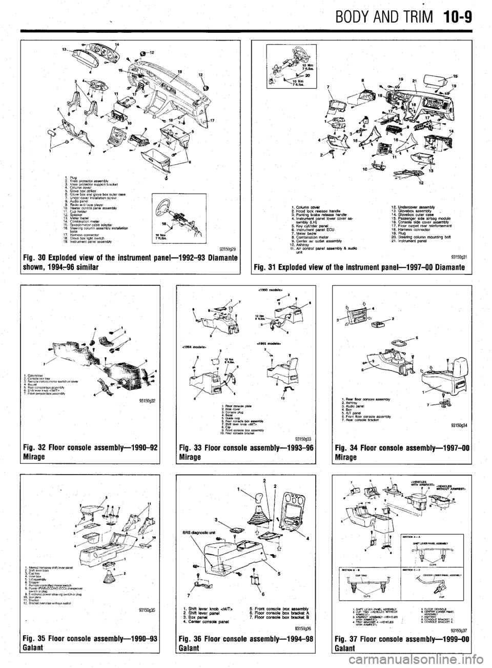
9315og29 Fig. 30 Exploded view of the instrument panel-1992-93 Diamante
shown, 1994796 similar
I Cam holder
2 Console box tray
3 Remote control mrror swatch drcover
1 Berrel
3 Rear cms~ie box assembly
3 Shift lever knob 4vitT>
7 Front eonsale box assembly
Fig. 32 Floor console assembly-1990-92
Yg. 33 Floor console assembly-1993-96
Nlirage
Mirage
1 Manual tmnsaxle shrft lever panel 2 Shrft lever boat 3. cup tray 4 lnnerbdx
6 Lrd assembly
6 Stopper 7 Remote cO”trOned nl,rrorSwl,Ch 8 PowerlFVWECONO (EC01 changeover
12 Bracket Wvcles wrthout addlo)
Fig. 35 Floor console assembly-l 990-93
Galant
4’
2
ia
9315og31 Fig. 31
Exploded view of the instrument
panel-l 997-00 Diamante
1. Column cover
2. Hood lock release handle
3. Parking brake release handle
4. Instrument anal lower cover as-
sembly (LH
P 5. Key cylinder panel
6. instrument panel ECU
7. Meter bezel
0. Combination meter 9. Center air outlet assembly
10. Ashtray
11. Air control panel assembly 8 audio
unit 12. Undercover assembly
13. Glovebox assembly
14. Glovebox outer case
15. Passenger side airbag module
16. Console side cover assemblv
17. Flow carpet rear rainforcem&t
18. Harness connector
19. Plug
20. Steering column mountlng bolt
21. Instrument panel
6 Rear cmsole box es%mbly
7
Shrff lever knob
6. CtQ 9 Front console box assembfk
10. Rear console bracket 9315og33
7 6
1. Shii lever knob &ATT:.
2. Shi lever panel
3. Box panel
4. Center console panel 5. Front console box assembly
6. Floor console box bracket A
7. floar console box bradret B
Fig. 36 Floor console assembly-1994-98
Galant
1. Rear floor console assembly
2. Ashtray
6. Front floor console assembly
7 Rear console bracket
Fig. 34 Floor console assembly-1997-00
Mirage
Fig. 37 Floor console assembly-l 999-00
Galant
Page 383 of 408
TROUBLESHOOTING INDEX 11-2
SECTION 1: ENGINE 11-2
SECTION 2: DRIVE TRAIN
11-3
SECTION 3:BRAKESYSTEM 11-3
SECTION 4:WHEELS,TIRES, STEERING,
AND SUSPENSION II-4
SECTION 5: ELECTRICAL
ACCESSORIES II-4
SECTION 6:lNSTRUMENTSAND
GAUGES II-5
SECTION 7:CLlMATE CONTROL II-5
DIAGNOSTIC PROCEDURES II-6
SECTION 1: ENGINE II-6
ENGINE STARTING PROBLEMS II-6
ENGINE RUNNING CONDITIONS II-7
ENGINE NOISES,ODORSAND
VIBRATIONS II-8
ENGINE ELECTRICALSYSTEM 11-8
ENGINE COOLING SYSTEM II-8
ENGINE EXHAUSTSYSTEM II-9
SECTION 2: DRIVE TRAIN
II-9
AUTOMATIC TRANSMISSION II-9
MANUALTRANSMISSION II-10
CLUTCH II-10
DIFFERENTIAL AND FINAL
DRIVE II-10
TRANSFER ASSEMBLY II-10
DRIVESHAFT II-10
AXLES II-II
OTHER DRIVE TRAIN
CONDITIONS II-II
SECTION 3:BRAKE SYSTEM II-II
BRAKESYSTEM
TROUBLESHOOTING II-II
SECTION 4:WHEELS, TIRES, STEERING
AND SUSPENSION II-12
WHEELSAND WHEEL
BEARINGS II-12
TIRES II-12
STEERING II-12
SUSPENSION II-12
DRIVING NOISES AND
VIBRATIONS II-13
SECTION 5:ELECTRlCAL
ACCESSORIES II-13 -
HEADLIGHTS II-13
TAIL, RUNNING AND SIDE MARKER
LIGHTS II-13
INTERIOR LIGHTS II-14
BRAKE LIGHTS II-14
WARNING LIGHTS II-14
TURN SlGNALAND4-WAYHAZARD
LIGHTS II-15
WINDSHIELD WIPERS II-15
SECTION 6:lNSTRUMENTSAND
GAUGUES II-15
I
SPEEDOMETER(CABLE
OPERATED) II-15
SPEEDOMETER(ELECTRONICALLY
OPERATED) II-16
FUEL,TEMPERATUREAkJD OIL
PRESSURE GAUGES II-16 SECTION 7:CLlMATECON
AIR CONDITIONER ll-
HEATER II-16 TR(
-16 IL II-16
Page 384 of 408
11-2 TROUBLESHOOTING
Condition
Section/Item Number
The following troubleshooting charts are divided into 7 sections covering engine, drive train, brakes, wheels/tires/steering/suspension, electrical accessories, instruments and gauges,
and climate control. The first portion (or index) consists of a list of symptoms, along with section and item numbers. After selecting the appropriate condition, refer to the corresponding
diagnostic procedure in the second portion’s specified location.
INDEX
Gasoline Engines Engine turns over, but will not start
Engine does not turn over when attempting to start
Engine stalls immediately when started
Starter motor spins, but does not engage
Engine is difficult to start when cold
Engine is difficult to start when hot
Diesel Engines Engine turns over but won’t start
Engine does not turn over when attempting to start
Engine stalls after starting
Starter motor spins, but does not engage
Engine is difficult to start I-A, 1
l-A, 2
I-A, 3
I-A, 4
I-A, 5
I-A, 6
I-A, 1
l-A, 2
I-A, 3
I-A, 4
l-A, 5
Gasoline Engines Engine runs poorly, hesitates
Engine lacks power
Engine has poorfuel economy
Engine runs on (diesels) when turned off
Engine knocks and pings during heavy acceleration, and on steep hills
Engine accelerates but vehicle does not gain speed
Diesel Engines Engine runs poorly
Engine lacks power l-B, 1
I-B, 2
l-B, 3
I-B, 4
l-B, 5
I-B, 6
l-B,-1
l-B, 2
Engine makes a knocking or pinging noise when accelerating
Starter motor grinds when used
Engine makes a screeching noise
Engine makes a growling noise
Engine makes a ticking or tapping noise
Engine makes a heavy knocking noise
Vehicle has a fuel odor when driven
Vehicle has a rotten egg odor when driven
Vehicle has a sweet odor when driven
Engine vibrates when idling
Engine vibrates during acceleration
Battery goes dead while driving
Battery goes dead overnight
Engine overheats
Engine loses coolant
Engine temperature remains cold when driving
Engine runs hot
Exhaust rattles at idle speed
Exhaust system vibrates when driving
Exhaust system seems too low
Exhaust seems loud l-C, 1
l-C, 2
l-C, 3
I-C, 4
l-C, 5
I-C, 6
l-C, 7
l-C, 8
I-C, 9
I-C, 10
l-C, 11
l-C, 1
I-C, 2
I-D, 1
I-D, 2
I-D, 3
I-D, 4
l-F, 1
l-F, 2
I-F, 3
I-F, 4
Page 386 of 408
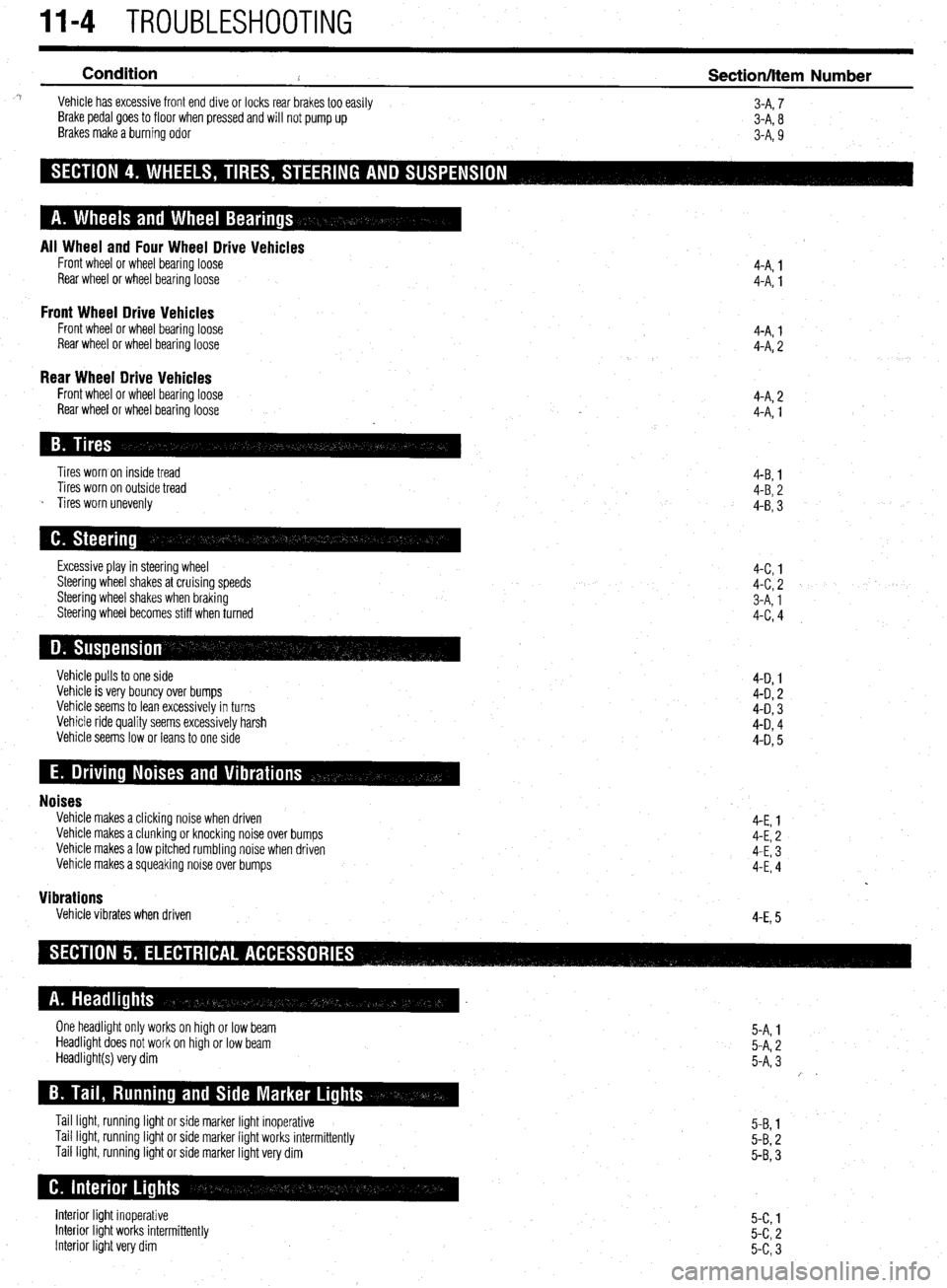
11-4 TROUBLESHOOTING
Condition
2 Section/Item Number ^i Vehicle has excessive front end dive or locks rear brakes too easily
3-A, 7
Brake pedal goes to floor when pressed and will not pump up
3-A, 8
Brakes make a burning odor
3-A, 9
All Wheel and Four Wheel Drive Vehicles Front wheel or wheel bearing loose
Rear wheel or wheel bearingloose
Front Wheel Drive Vehicles Front wheel or wheel bearing loose
Rear wheel or wheel bearing loose 4-A. 1
4-A: 1
4-A, 1
4-A, 2
Rear Wheel Drive Vehicles Front wheel or wheel bearing loose
Rear wheel or wheel bearing loose 4-A, 2
4-A, 1
Tires worn on inside tread
Tires worn on outside tread
s Tires worn unevenly 4-B, 1
4-B, 2
4-B, 3
Excessive play in steering wheel
Steering wheel shakes at cruising speeds
Steering wheel shakes when braking
Steering wheel becomes stiff when turned 4-c, 1
4-c, 2
3-A, 1
4-c, 4
Vehicle pulls to one side
Vehicle is very bouncy over bumps
Vehicle seems to lean excessively in turns
Vehicle ride quality seems excessively harsh
Vehicle seems low or leans to one side 4-D 1
4-D, 2
4-D, 3
4-D, 4
4-D, 5
Noises Vehicle makes a clicking noise when driven
Vehicle makes a clunking or knocking noise over bumps
Vehicle makes a low pitched rumbling noise when driven
Vehicle makes a squeaking noise over bumps
Vibrations Vehicle vibrates when driven 4-E, 1
4-E, 2
4-E, 3
4-E, 4
4-E, 5
One headlight only works on high or low beam
Headlight does not work on high or low beam
Headlight(s) very dim
Tail light, running light or side marker light inoperative
Tail light, running light or side marker light works intermittently
Tail light, running light or side marker light very dim 5-A, 1
5-A, 2
5-A, 3
/ .
5-B, 1
5-B, 2
5-B, 3
Interior light inoperative
Interior light works intermittently
Interior light very dim 5-c, 1
5-c, 2
5-c, 3
Page 394 of 408
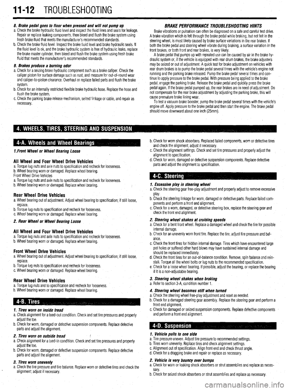
IJront Wheel or Wheel Bearing Loose
All Wheel and Four Wheel Drive Vehicles a. Torque lug nuts and axle nuts to specification and recheck for looseness.
b. Wheel bearing worn or damaged. Replace wheel bearing.
Front Wheel Drive Vehicles
a. Torque lug nuts and axle nuts to specification and recheck for looseness.
b. Wheel bearing worn or damaged. Replace wheel bearing.
Rear Wheel Drive Vehicles a. Wheel bearing out of adjustment. Adjust wheel bearing to specification; if still loose,
replace.
b. Torque lug nuts to specification and recheck for looseness.
c. Wheel bearing worn or damaged. Replace wheel bearing.
2. Rear Wheel or Wheel Bearing Loose
All Wheel and Four Wheel Drive Vehicles a. Torque lug nuts and axle nuts to specification and recheck for looseness.
b. Wheel bearing worn or damaged. Replace wheel bearing.
Front Wheel Drive Vehicles a. Wheel bearing out of adjustment. Adjust wheel bearing to specification; if still loose,
replace.
b. Torque lug nuts to specification and recheck for looseness.
c. Wheel bearing worn or damaged. Replace wheel bearing.
Rear Wheel Drive Vehicles a. Torque lug nuts and to specification and recheck for looseness.
b. Wheel bearing worn or damaged. Replace wheel bearing.
11-12 TROUBLESHOOTING
8. Brake pedal goes to floor when pressed and will not pump up
a. Check the brake hydraulic fluid level and inspect the fluid lines and seals for leakage.
Repair or replace leaking components, then bleed and flush the brake system using
fresh brake fluid that meets the manufacturer’s recommended standards.
b. Check the brake fluid level. Inspect the brake fluid level and brake hydraulic seals. If
the fluid level is ok, and the brake hydraulic system is free of hydraulic leaks, replace
the brake master cylinder, then bleed and flush the brake system using fresh brake
fluid that meets the manufacturer’s recommended standards.
9. Brakes produce a burning odor
a. Check for a seizing brake hydraulic component such as a brake caliper. Check the
caliper piston for surface damage such as rust, and measure for out-of-round wear
and caliper-to-piston clearance. Overhaul or replace failed parts and flush the brake
system.
b. Check for an internally restricted flexible brake hydraulic hose. Replace the hose and
flush the brake system.
c. Check the parking brake release mechanism, seized linkage or cable, and repair as
necessary. BRAKE PERFORMANCE TROU5LESHOOTINc; HIIVTS Brake vibrations or pulsation can often be diagnosed on a safe and careful test drive.
A brake vibration which is felt through the brake pedal while braking, but not felt in the
steering wheel, is most likely caused by brake surface variations in the rear brakes. If
both the brake pedal and steering wheel vibrate during braking, a surface variation in the
front brakes, or both front and rear brakes, is very likely.
A brake pedal that pumps up with repeated use can be caused by air in the brake hy-
draulic system or, if the vehicle is equipped with rear drum brakes, the brake adjusters
may be seized or out of adjustment. A quick test for brake adjustment on vehicles with
rear drum brakes is to pump the brake pedal several times with the vehicle’s engine not
running and the parking brake released. Pump the brake pedal several times and con-
tinue to apply pressure to the brake pedal. With pressure being applied to the brake
pedal, engage the parking brake. Release the brake pedal and quickly press the brake
pedal again. If the brake pedal pumped up, the rear brakes are in need of adjustment. Do
not compensate for the rear brake adjustment by adjusting the parking brake, this will
cause premature brake lining wear.
To test a vacuum brake booster, pump the brake pedal several times with the vehicle’s
engine off. Apply pressure to the brake pedal and then start the engine. The brake pedal
should move downward about one inch (25mm).
1. Tires worn on inside tread
a. Check alignment for a toed-out condition. Check and set tire pressures and properly
adjust the toe.
b. Check for worn, damaged or defective suspension components. Replace defective
parts and adjust the alignment.
2. Tires worn on outside tread e
a. Check alignment for a toed-in condition. Check and set tire pressures and properly
adjust the toe.
b. Check for worn, damaged or defective suspension components. Replace defective
parts and adjust the alignment.
3. Tires worn unevenly
a. Check the tire pressure and tire balance. Replace worn or defective tires and check the
.
alignment; adjust if necessary. b. Check for worn shock absorbers. Replaced failed components, worn or defective tires
and check the alignment; adjust if necessary.
c. Check the alignment settings. Check and set tire pressures and properly adjust the
alignment to specification.
d. Check for worn, damaged or defective suspension components. Replace defective
parts and adjust the alignment to specification,
1. Excessive play in steering wheel
a. Check the steering gear free-play adjustment and properly adjust to remove excessive
play.
b. Check the steering linkage for worn, damaged or defective parts. Replace failed com-
ponents and perform a front end alignment.
c. Check for a worn, damaged, or defective steering box, replace the steering gear and
check the front end alignment.
2. Steering wheel shakes at cruising speeds
a. Check for a bent front wheel. Replace a damaged wheel and check the tire for possible
internal damage.
b. Check for an unevenly worn front tire. Replace the tire, adjust tire pressure and bal-
ance.
c. Check the front tires for hidden internal damage. Tires which have encountered large
pot holes or suffered other hard blows may have sustained internal damage and
should be replaced immediately.
d. Check the front tires for an out-of-balance condition. Remove, spin balance and rein-
stall. Torque all the wheel bolts or lug nuts to the recommended specification.
e. Check for a loose wheel bearing. If possible, adjust the bearing, or replace the bearing
if it is a non-adjustable bearing.
3. Steering wheel shakes when braking
a. Refer to section 3-A, condition number 1.
4. Steering wheel becomes stiff when turned
a. Check the steering wheel free-play adjustment and reset as needed.
b. Check for a damaged steering gear assembly. Replace the steering gear and perform a
front end alignment.
c. Check for damaged or seized suspension components. Replace defective components
and perform a front end alignment.
1. Vehicle pulls to one side
a. Tire pressure uneven. Adjust tire pressure to recommended settings.
b. Tires worn unevenly. Replace tires and check alignment settings.
c. Alignment out of specification. Align front end and check thrust angle.
d. Check for a dragging brake and repair or replace as necessary.
2. Vehicle is very bouncy over bumps
a. Check for worn or leaking shock absorbers or strut assemblies and replace as neces-
sary.
b. Check for seized shock absorbers or strut assemblies and replace as necessary.
Page 395 of 408
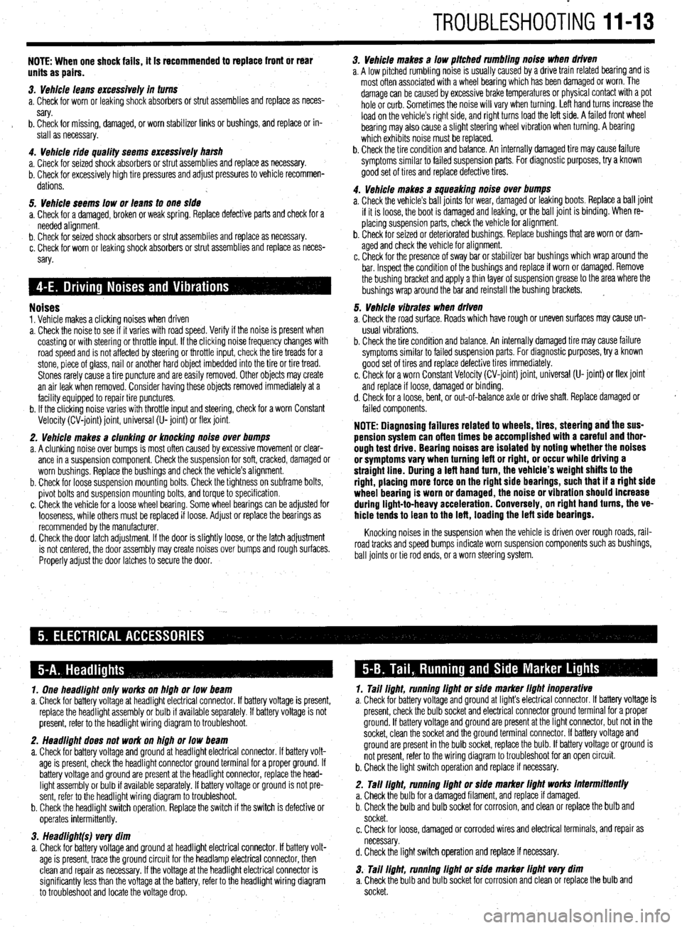
TROUBLESHOOTING 11-13
NOTE: When one shock fails, ft is recommended to replace front or rear
units as pairs.
3. Vehicle leans excessively in turns
a. Check for worn or leaking shock absorbers or strut assemblies and replace as neces-
sary.
b. Check for missing, damaged, or worn stabilizer links or bushings, and replace or in-
stall as necessary.
4. Vehicle ride quality seems excessively ha&h
a. Check for seized shock absorbers or strut assemblies and replace as necessary.
b. Check for excessively high tire pressures and adjust pressures to vehicle recommen-
dations.
5. Vehicle seems low or leans to one side
a. Check for a damaged, broken or weak spring. Replace defective parts and check for a
needed alignment.
b. Check for seized shock absorbers or strut assemblies and replace as necessary.
c. Check for worn or leaking shock absorbers or strut assemblies and replace as neces-
sary.
Noises 1. Vehicle makes a clicking noises when driven
a. Check the noise to see if it varies with road speed. Verify if the noise is present when
coasting or with steering or throttle input. If the clicking noise frequency changes with
road speed and is not affected by steering or throttle input, check the tire treads for a
stone, piece of glass, nail or another hard object imbedded into the tire or tire tread.
Stones rarely cause a tire puncture and are easily removed. Other objects may create
an air leak when removed. Consider having these objects removed immediately at a
facility equipped to repair tire punctures.
b. If the clicking noise varies with throttle input and steering, check for a worn Constant
Velocity (CV-joint) joint, universal (U- joint) or flex joint.
2. Vehicle makes a clunking or knocking noise over bumps
a. A clunking noise over bumps is most often caused by excessive movement or clear-
ance in a suspension component. Check the suspension for soft, cracked, damaged or
worn bushings. Replace the bushings and check the vehicle’s alignment.
b. Check for loose suspension mounting bolts. Check the tightness on subframe bolts,
pivot bolts and suspension mounting bolts, and torque to specification.
c. Check the vehicle for a loose wheel bearing. Some wheel bearings can be adjusted for
looseness, while others must be replaced if loose. Adjust or replace the bearings as
recommended by the manufacturer.
d. Check the door latch adjustment. If the door is slightly loose, or the latch adjustment
is not centered, the door assembly may create noises over bumps and rough surfaces.
Properly adjust the door latches to secure the door. 3. Vehicle makes a low pitched rumbling noise when driven
a. A low pitched rumbling noise is usually caused by a drive train related bearing and is
most often associated with a wheel bearing which has been damaged or worn. The
damage can be caused by excessive brake temperatures or physical contact with a pot
hole or curb. Sometimes the noise will vary when turning. Left hand turns increase the
load on the vehicle’s right side, and right turns load the left side. A failed front wheel
bearing may also cause a slight steering wheel vibration when turning. A bearing
which exhibits noise must be replaced.
b. Check the tire condition and balance. An internally damaged tire may cause failure
symptoms similar to failed suspension parts. For diagnostic purposes, try a known
good set of tires and replace defective tires.
4. Vehicle makes a squeaking noise over bumps
a. Check the vehicle’s ball joints for wear, damaged or leaking boots. Replace a ball joint
if it is loose, the boot is damaged and leaking, or the ball joint is binding. When re-
placing suspension parts, check the vehicle for alignment.
b. Check for seized or deteriorated bushings. Replace bushings that are worn or dam-
aged and check the vehicle for alignment.
c. Check for the presence of sway bar or stabilizer bar bushings which wrap around the
bar. Inspect the condition of the bushings and replace if worn or damaged. Remove
the bushing bracket and apply a thin layer of suspension grease to the area where the
bushings wrap around the bar and reinstall the bushing brackets. ~
5. Vehicle vibrates when driven
a. Check the road surface. Roads which have rough or uneven surfaces may cause un-
usual vi brations.
b. Check the tire condition and balance. An internally damaged tire may cause failure
symptoms similar to failed suspension parts. For diagnostic purposes, try a known
good set of tires and replace defective tires immediately.
c. Check for a worn Constant Velocity (CV-joint) joint, universal (U- joint) or flex joint
and replace if loose, damaged or binding.
d. Check for a loose, bent, or out-of-balance axle or drive shaft. Replace damaged or
failed components.
NOTE: Diagnosing failures related to wheels, tires, steering and the sus-
pension system can often times be accomplished with a careful and thor-
ough test drive. Bearing noises are isolated by noting whether the noises
or symptoms vary when turning left or right, or occur while driving a
straight line. During a teft hand turn, the vehicle’s weight shifts to the
right, placing more force on the right side bearings, such that if a right side
wheel bearing is worn or damaged, the noise or vibration should increase
during light-to-heavy acceleration. Conversely, on right hand turns, the ve-
hicle tends to lean to the left, loading the left side bearings.
Knocking noises in the suspension when the vehicle is driven over rough roads, rail-
road tracks and speed bumps indicate worn suspension components such as bushings,
ball joints or tie rod ends, or a worn steering system.
1. One headlight only works on high or low beam
a. Check for battery voltage at headlight electrical connector. If battery voltage is present,
replace the headlight assembly or bulb if available separately. If battery voltage is not
present, refer to the headlight wiring diagram to troubleshoot.
2. Headlight does not work on high or low beam
a. Check for battery voltage and ground at headlight electrical connector. If battery volt-
age is present, check the headlight connector ground terminal for a proper ground. If
battery voltage and ground are present at the headlight connector, replace the head-
light assembly or bulb if available separately. If battery voltage or ground is not pre-
sent, refer to the headlight wiring diagram to troubleshoot.
b. Check the headlight switch operation. Replace the switch if the switch is defective or
ooerates intermittentlv. 1. Tail light, running light or side marker light inoperative
a. Check for battery voltage and ground at light’s electrical connector. If battery voltage is
present, check the bulb socket and electrical connector ground terminal for a proper
ground. If battery voltage and ground are present at the light connector, but not in the
socket, clean the socket and the ground terminal connector. If battery voltage and
ground are present in the bulb socket, replace the bulb. If battery voltage or ground is
not present, refer to the wiring diagram to troubleshoot for an open circuit.
b. Check the light switch operation and replace if necessary.
2. Tall light, running light or side marker light works intermittently
a. Check the bulb for a damaged filament, and replace if damaged.
b. Check the bulb and bulb socket for corrosion, and clean or replace the bulb and
socket.
w 3. Headlight(s) very dim
a. Check for battery voltage and ground at headlight electrical connector. If battery volt-
age is present, trace the ground circuit for the headlamp electrical connector, then
clean and repair as necessary. If the voltage at the headlight electrical connector is
significantly less than the voltage at the battery, refer to the headlight wiring diagram
to troubleshoot and locate the voltage drop. c. Check for loose, damaged or corroded wires and electrical terminals, and repair as
necessary.
d. Check the light switch operation and replace if necessary.
3. Tail light, running light or side marker light very dim
a. Check the bulb and bulb socket for corrosion and clean or replace the bulb and
socket.
Page 406 of 408
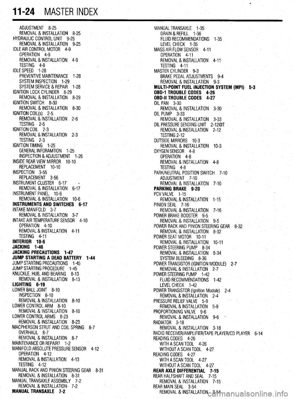
l
II-24 MASTER INDEX
ADJUSTMENT 8-25
REMOVAL &INSTALLATION 8-25
HYDRAULIC CONTROL UNIT 9-25
REMOVAL & INSTALLATION 9-25
IDLE AIR CONTROLMOTOR 4-9
OPERATION 4-9
REMOVAL&INSTALLATION 4-9
TESTING 4-9
IDLESPEED 1-28
PREVENTIVEMAINTENANCE 1-28
SYSTEM INSPECTION 1-29
SYSTEMSERVlCE&REPAlR 1-28
IGNITION LOCK CYLINDER 8-29
REMOVAL & INSTALLATION 8-29
IGNITION SWITCH 8-30
REMOVAL & INSTALLATION 8-30
IGNITION COIL(s) 2-5
REMOVAL&INSTALLATION 2-6
TESTING . 2-5
IGNITION COIL 2-3
REMOVAL&INSTALLATION 2-3
TESTING 2-3
IGNITION TIMING l-25
GENERALINFORAMTION l-25
INSPECTION&ADJUSTMENT l-26
INSIDE REAR VIEW MIRROR
IO-IO
REPLACEMENT IO-IO
INSPECTION 3-55
REPLACEMENT 3-56
INSTRUMENT CLUSTER 6-17
REMOVAL&INSTALLATION 6-I;
INSTRUMENTPANEL IO-6
REMOVAL &INSTALLATION IO-6
INSTRUMENTS AND SWITCHES 6-17
INTAKE MANIFOLD 3-7
REMOVAL &INSTALLATION 3-7
INTAKEAIRTEMPERATURESENSOR 4-10
OPERATION 4-10
REMOVAL&INSTALLATION 4-11
TESTING 4-11
INTERIOR 1 O-6
JACKING I-46
. JACKING PRECAUTIONS 1-47
JUMP STARTING A DEAD BATTERY 1-44
JUMPSTARTING PRECAUTIONS l-45
JUMPSTARTING PROCEDURE l-45
KNUCKLE,HUB, AND BEARING 8-13
REMOVAL &INSTALLATION 8-13
LIGHTING 6-19
LOWER BALLJOINT 8-10
INSPECTION 8-10
REMOVAL & INSTALLATION 8-10
LOWER CONTROLARM 8-10
REMOVAL&INSTALLATION 8-10
LOWER CONTROL ARMS 8-23
REMOVAL & INSTALLATION 8-23
MACPHERSONSTRUTAND COILSPRING
8-7
OVERHAUL 8-7
REMOVAL & INSTALLATION 8-7
MAINTENANCEORREPAIR? l-2
MANIFOLDABSOLUTEPRESSURESENSOR
4-12
OPERATION 4-12
REMOVAL&INSTALLATION 4-13
TESTING 4-12
MANUAL RACK AND PINION STEERING GEAR
8-31
REMOVAL & INSTALLATION 8-31
MANUALTRANSAXLEASSEMBLY 7-2
REMOVAL & INSTALLATION. 7-2
MANUAL TRANSAXLE 7-2 MANUALTRANSAXLE l-35
DRAIN &REFILL l-36
FLUID RECOMMENDATIONS l-35
LEVEL CHECK l-35
MASSAIRFLOWSENSOR 4-11
OPERATION 4-11
REMOVAL&INSTALLATION 4-11
TESTING 4-11
MASTER CYLINDER 9-3
BRAKE PEDALADJUSTMENTS 9-4
REMOVAL & INSTALLATION 9-3
MULTI-POINT FUEL INJECTION SYSTEM (MPI) 5-3
DBD-1 TROUBLE CODES 4-26
OBD-II TROUBLE CODES 4-27
OIL PAN 3-30
REMOVAL & INSTALLATION 3-30
OIL PUMP 3-33
REMOVAL & INSTALLATION 3-33
OIL PRESSURESENDING UNIT 2-12@T
REMOVAL&INSTALLATION 2-1.2
TESTING 2-12
OUTSIDE MIRRORS IO-3
REMOVAL&INSTALLATION IO-3
OXYGENSENSOR 4-8
OPERATION 4-8
REMOVAL&INSTALLATION 4-8
TESTING 4-8
PARK/NEUTRAL POSITIONSWITCH 7-10
ADJUSTMENT 7-10
REMOVAL & INSTALLATION 7-10
PARKING BRAKE 9-20
PCVVALVE l-15
REMOVAL&INSTALLATION I-15
PINION SEAL 7-16
REMOVAL &INSTALLATION 7-16
POWER BRAKEBOOSTER 9-5
REMOVAL &INSTALLATION 9-5
POWER RACK AND PINION STEERING GEAR 8-32
REMOVAL &INSTALLATION 8-32
POWERSEATMOTOR IO-11
REMOVAL & INSTALLATION IO-11
POWER STEERING PUMP 8-34
REMOVAL & INSTALLATION 8-34
SYSTEM BLEEDING 8-36
POWER TRANSlSTOR(IGNITION MODULE) 2-7
REMOVAL&INSTALLATION 2-7
POWERSTEERING PUMP l-42
FLUID RECOMMENDATIONS l-42
LEVELCHECK l-42
POWER TRANSlSTOR(Ignition Module) 2-4
REMOVAL&INSTALLATION 2-4
PRESSURERELIEFVALVE 5-9
REMOVAL&INSTALLATION 5-9
PROPORTIONING VALVE 9-6
REMOVAL & INSTALLATION 9-6 *
RADIATOR 3-18
REMOVAL &INSTALLATION 3-18
RADIO RECEIVER/AMPLIFIER/TAPE PLAYER/CD PLAYER 6-14
READING CODES 4-26
WITHASCANTOOL 4-26
WITHOUTASCANTOOL 4-27
READING CODES 4-27
WITHASCANTOOL 4-27
WITHOUTASCANTOOL 4-27
REAR AXLE DIFFERENTIAL 7-15
REAR HALFSHAFTAND SEAL 7-15
REMOVAL&INSTALLATION 7-15
REAR MAIN SEAL 3-54
REMOVAL & INSTALLATION 3-54