2024 FORD F650/750 instrument cluster
[x] Cancel search: instrument clusterPage 181 of 386
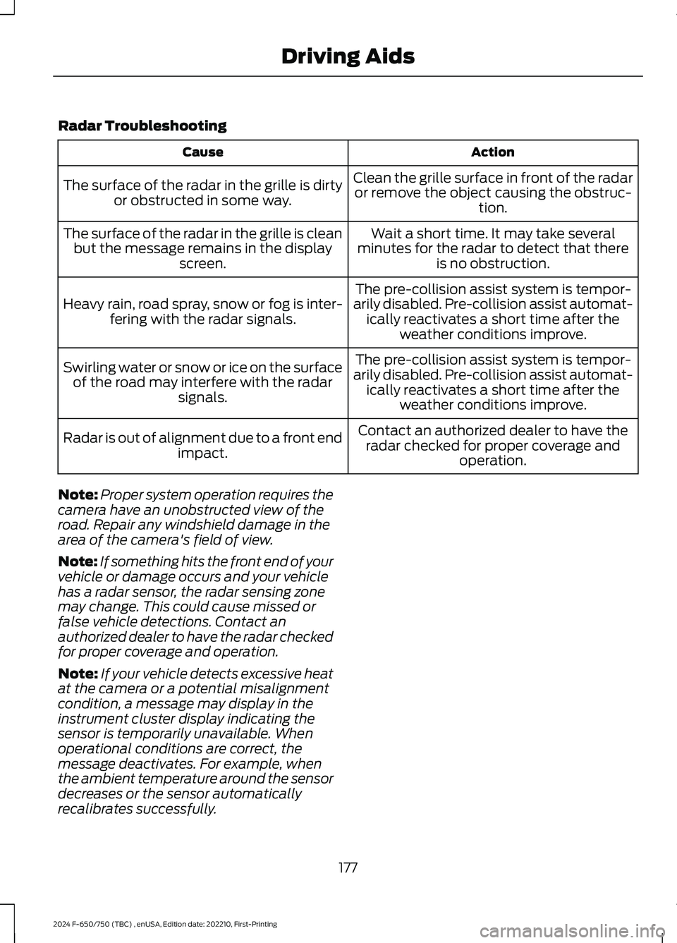
Radar Troubleshooting
ActionCause
Clean the grille surface in front of the radaror remove the object causing the obstruc-tion.
The surface of the radar in the grille is dirtyor obstructed in some way.
Wait a short time. It may take severalminutes for the radar to detect that thereis no obstruction.
The surface of the radar in the grille is cleanbut the message remains in the displayscreen.
The pre-collision assist system is tempor-arily disabled. Pre-collision assist automat-ically reactivates a short time after theweather conditions improve.
Heavy rain, road spray, snow or fog is inter-fering with the radar signals.
The pre-collision assist system is tempor-arily disabled. Pre-collision assist automat-ically reactivates a short time after theweather conditions improve.
Swirling water or snow or ice on the surfaceof the road may interfere with the radarsignals.
Contact an authorized dealer to have theradar checked for proper coverage andoperation.
Radar is out of alignment due to a front endimpact.
Note:Proper system operation requires thecamera have an unobstructed view of theroad. Repair any windshield damage in thearea of the camera's field of view.
Note:If something hits the front end of yourvehicle or damage occurs and your vehiclehas a radar sensor, the radar sensing zonemay change. This could cause missed orfalse vehicle detections. Contact anauthorized dealer to have the radar checkedfor proper coverage and operation.
Note:If your vehicle detects excessive heatat the camera or a potential misalignmentcondition, a message may display in theinstrument cluster display indicating thesensor is temporarily unavailable. Whenoperational conditions are correct, themessage deactivates. For example, whenthe ambient temperature around the sensordecreases or the sensor automaticallyrecalibrates successfully.
177
2024 F-650/750 (TBC) , enUSA, Edition date: 202210, First-PrintingDriving Aids
Page 213 of 386
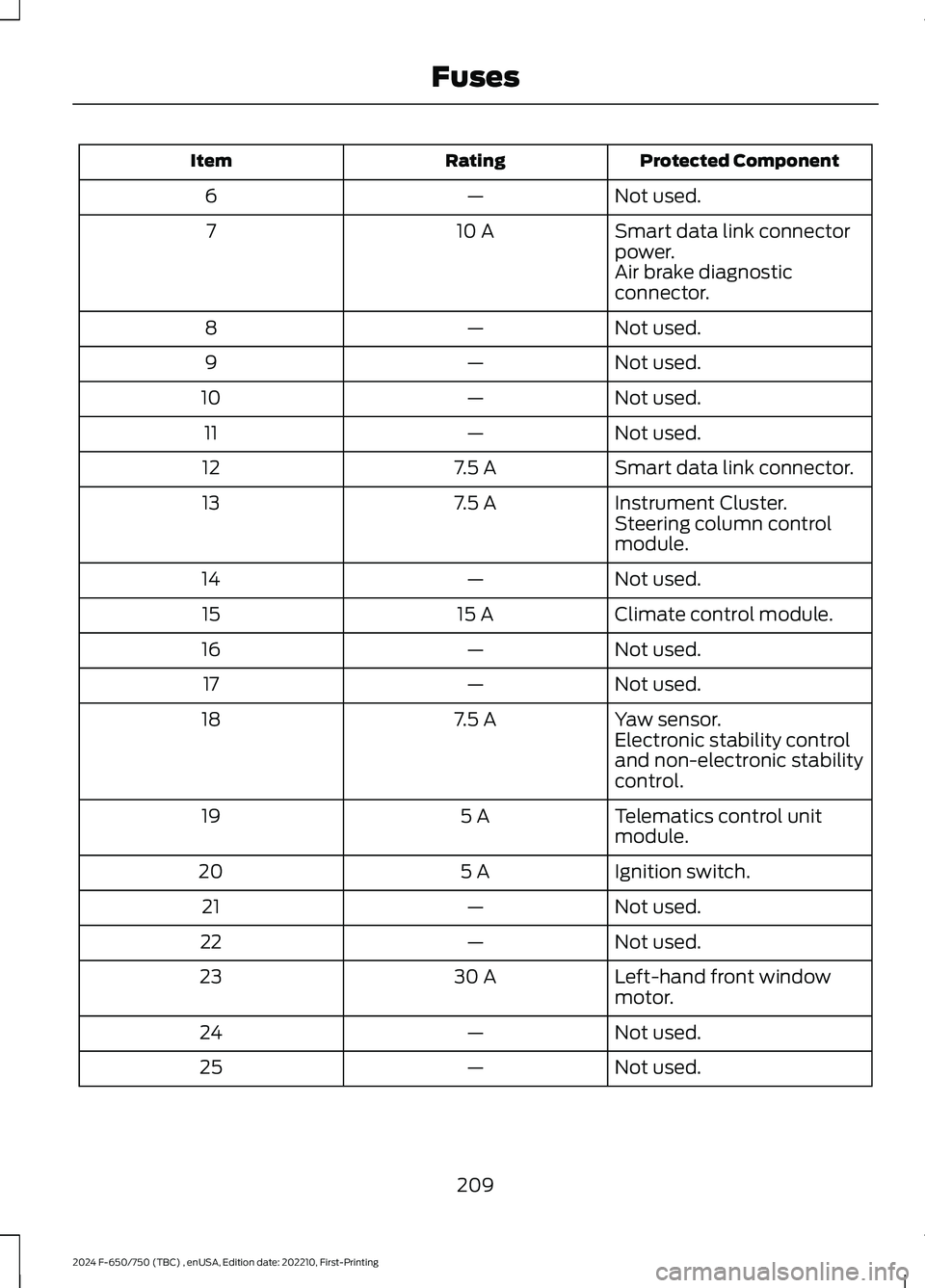
Protected ComponentRatingItem
Not used.—6
Smart data link connectorpower.10 A7
Air brake diagnosticconnector.
Not used.—8
Not used.—9
Not used.—10
Not used.—11
Smart data link connector.7.5 A12
Instrument Cluster.7.5 A13Steering column controlmodule.
Not used.—14
Climate control module.15 A15
Not used.—16
Not used.—17
Yaw sensor.7.5 A18Electronic stability controland non-electronic stabilitycontrol.
Telematics control unitmodule.5 A19
Ignition switch.5 A20
Not used.—21
Not used.—22
Left-hand front windowmotor.30 A23
Not used.—24
Not used.—25
209
2024 F-650/750 (TBC) , enUSA, Edition date: 202210, First-PrintingFuses
Page 218 of 386
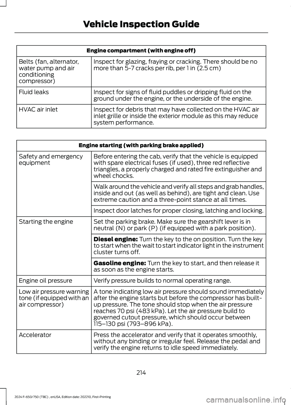
Engine compartment (with engine off)
Inspect for glazing, fraying or cracking. There should be nomore than 5-7 cracks per rib, per 1 in (2.5 cm)Belts (fan, alternator,water pump and airconditioningcompressor)
Inspect for signs of fluid puddles or dripping fluid on theground under the engine, or the underside of the engine.Fluid leaks
Inspect for debris that may have collected on the HVAC airinlet grille or inside the exterior module as this may reducesystem performance.
HVAC air inlet
Engine starting (with parking brake applied)
Before entering the cab, verify that the vehicle is equippedwith spare electrical fuses (if used), three red reflectivetriangles, a properly charged and rated fire extinguisher andwheel chocks.
Safety and emergencyequipment
Walk around the vehicle and verify all steps and grab handles,inside and out (as well as behind), are tight and clean. Useextreme caution and a three-point stance at all times.
Inspect door latches for proper closing, latching and locking.
Set the parking brake. Make sure the gearshift lever is inneutral (N) or park (P) (if equipped with a park position).Starting the engine
Diesel engine: Turn the key to the on position. Turn the keyto start when the wait to start indicator light in the instrumentcluster turns off.
Gasoline engine: Turn the key to start, and then release itas soon as the engine starts.
Verify pressure builds to normal operating range.Engine oil pressure
A tone indicating low air pressure should sound immediatelyafter the engine starts but before the compressor has built-up pressure. The tone should stop when the air pressurereaches 70 psi (483 kPa). Let the air pressure build togoverned cutout pressure, which should occur between115–130 psi (793–896 kPa).
Low air pressure warningtone (if equipped with anair compressor)
Press the accelerator and verify that it operates smoothly,without any binding or irregular feel. Release the pedal andverify the engine returns to idle speed immediately.
Accelerator
214
2024 F-650/750 (TBC) , enUSA, Edition date: 202210, First-PrintingVehicle Inspection Guide
Page 233 of 386
•Frequent low-speed operation, orconsistent heavy traffic less than25 mph (40 km/h).
•Operating in severe dust conditions.
•Operating the vehicle off road.
•Towing a trailer over 1,000 mi(1,600 km).
•Sustained, high-speed driving at thegross vehicle weight rating.
•Use of fuels with sulfur content otherthan ultra-low sulfur diesel (ULSD).
•Use of high-sulfur diesel fuel.
Only use engine oil that meets ourspecifications. See Capacities andSpecifications (page 291).
OIL CHANGE INDICATOR
RESET
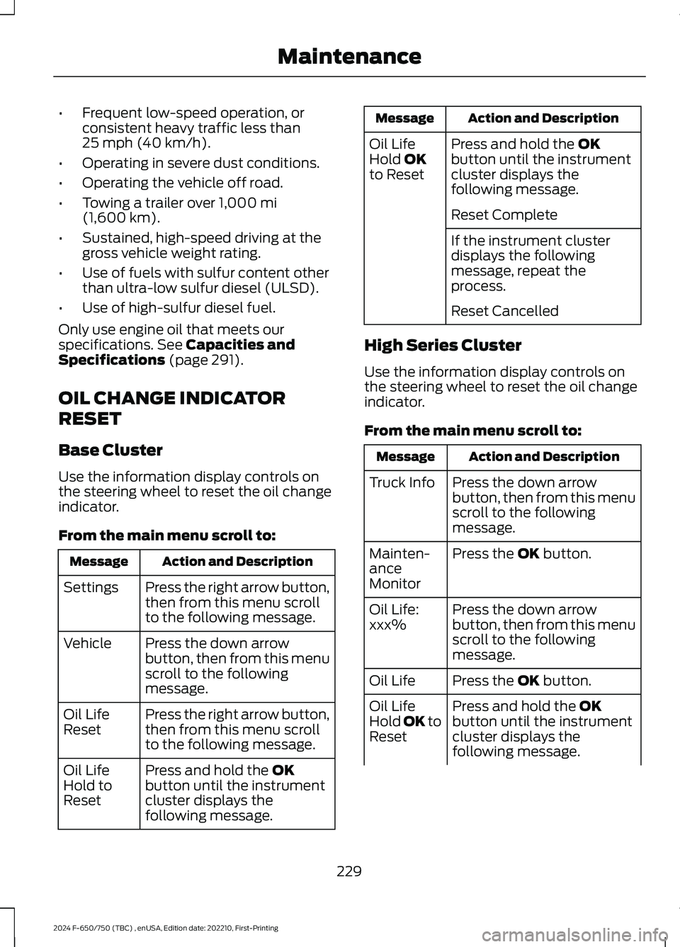
Base Cluster
Use the information display controls onthe steering wheel to reset the oil changeindicator.
From the main menu scroll to:
Action and DescriptionMessage
Press the right arrow button,then from this menu scrollto the following message.
Settings
Press the down arrowbutton, then from this menuscroll to the followingmessage.
Vehicle
Press the right arrow button,then from this menu scrollto the following message.
Oil LifeReset
Press and hold the OKbutton until the instrumentcluster displays thefollowing message.
Oil LifeHold toReset
Action and DescriptionMessage
Press and hold the OKbutton until the instrumentcluster displays thefollowing message.
Oil LifeHold OKto Reset
Reset Complete
If the instrument clusterdisplays the followingmessage, repeat theprocess.
Reset Cancelled
High Series Cluster
Use the information display controls onthe steering wheel to reset the oil changeindicator.
From the main menu scroll to:
Action and DescriptionMessage
Press the down arrowbutton, then from this menuscroll to the followingmessage.
Truck Info
Press the OK button.Mainten-anceMonitor
Press the down arrowbutton, then from this menuscroll to the followingmessage.
Oil Life:xxx%
Press the OK button.Oil Life
Press and hold the OKbutton until the instrumentcluster displays thefollowing message.
Oil LifeHold OK toReset
229
2024 F-650/750 (TBC) , enUSA, Edition date: 202210, First-PrintingMaintenance
Page 234 of 386
Action and DescriptionMessage
Oil Life: 100%
When the oil change indic-ator resets, the instrumentcluster displays 100%.
Repeat the process if the oilchange indicator does notreset.
CHANGING THE ENGINE AIR
FILTER - 6.7L DIESEL
Air Filter Restriction Gauge
WARNING: To reduce the risk ofvehicle damage and personal burninjuries, do not start your engine with theair cleaner removed and do not removeit while the engine is running.
Note:Operating your vehicle in heavysnowfall or extreme rain conditions mayallow excessive amounts of snow or waterinto the air intake system. This could plugor soak the air filter and cause the engine tolose power or shut down.
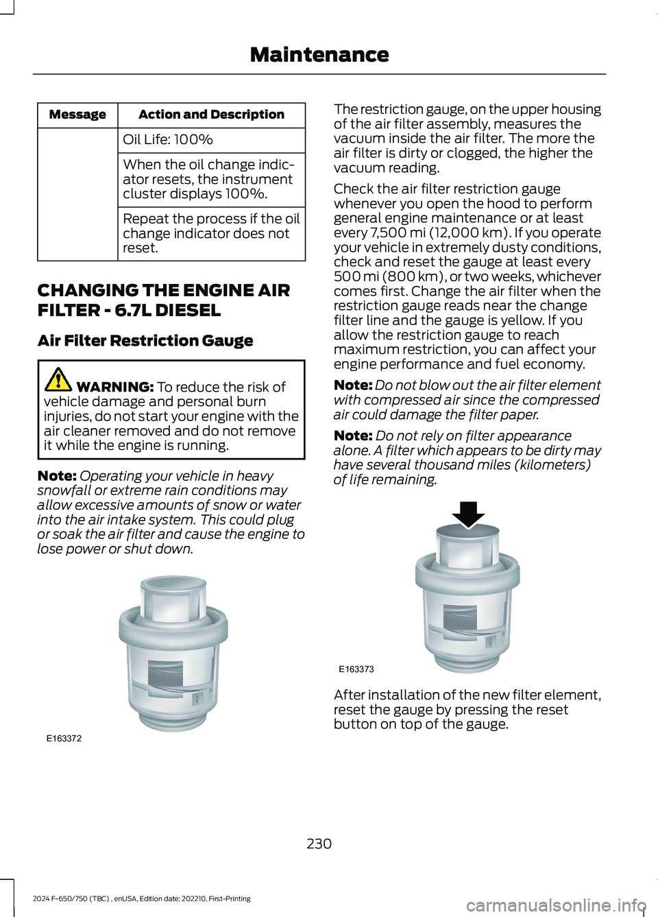
The restriction gauge, on the upper housingof the air filter assembly, measures thevacuum inside the air filter. The more theair filter is dirty or clogged, the higher thevacuum reading.
Check the air filter restriction gaugewhenever you open the hood to performgeneral engine maintenance or at leastevery 7,500 mi (12,000 km). If you operateyour vehicle in extremely dusty conditions,check and reset the gauge at least every500 mi (800 km), or two weeks, whichevercomes first. Change the air filter when therestriction gauge reads near the changefilter line and the gauge is yellow. If youallow the restriction gauge to reachmaximum restriction, you can affect yourengine performance and fuel economy.
Note:Do not blow out the air filter elementwith compressed air since the compressedair could damage the filter paper.
Note:Do not rely on filter appearancealone. A filter which appears to be dirty mayhave several thousand miles (kilometers)of life remaining.
After installation of the new filter element,reset the gauge by pressing the resetbutton on top of the gauge.
230
2024 F-650/750 (TBC) , enUSA, Edition date: 202210, First-PrintingMaintenanceE163372 E163373
Page 242 of 386
Follow your community’s regulations andstandards for recycling and disposing ofautomotive fluids.
Severe Climates
If you drive in extremely cold climates:
•It may be necessary to increase thecoolant concentration above 50%.
•A coolant concentration of 60%provides improved freeze pointprotection.Coolant concentrationsabove 60% decrease the overheatprotection characteristics of thecoolant and may cause enginedamage.
If you drive in extremely hot climates:
•You can decrease the coolantconcentration to 40%.
•Coolant concentrations below 40%decrease the freeze and corrosionprotection characteristics of thecoolant and may cause enginedamage.
Vehicles driven year-round in non-extremeclimates should use prediluted enginecoolant for optimum cooling system andengine protection.
Coolant Change
At specific mileage intervals, as listed inthe scheduled maintenance information,the coolant should be changed. Theinstrument cluster display may display amessage to change coolant at this time.Add prediluted coolant approved to thecorrect specification. See Capacities andSpecifications (page 291).
Engine-driven Cooling Fan (FanClutch)
Your vehicle may have an engine drivencooling fan drive (also called a fan clutch).This fan drive changes the fan speed tomatch the vehicle’s changing cooling airflow requirements. Fan speed, fan noiselevel and fuel consumption all increasebased on the driving conditions thatinclude trailer towing, hill climbing, heavyloads, high speed and high ambienttemperature, individually or in combination.
The fan drive is designed to provide theminimum fan speed (and resultingminimum fan noise and fuel consumption)required to meet the ever changing vehiclecooling air flow requirements. You can hearfan noise increasing and decreasing as theengine power requirements and vehicledriving conditions change as you drive. Thisis to be expected as being normal to theoperation of your vehicle. High levels of fannoise might also be heard when yourengine is first started, and should normallydecrease after driving for a short time.
ENGINE COOLANT CHECK -
7.3L
WARNING: Do not remove thecoolant reservoir cap when the engine ison or the cooling system is hot. Wait 10minutes for the cooling system to cooldown. Cover the coolant reservoir capwith a thick cloth to prevent thepossibility of scalding and slowly removethe cap. Failure to follow this instructioncould result in personal injury.
WARNING: Do not put coolant inthe windshield washer reservoir. Ifsprayed on the windshield, coolant couldmake it difficult to see through thewindshield.
238
2024 F-650/750 (TBC) , enUSA, Edition date: 202210, First-PrintingMaintenance
Page 247 of 386
At this time, you may notice the coolanttemperature gauge moves toward the redzone and a message may appear in theinformation display.
You may notice a reduction in vehiclespeed caused by reduced engine power inorder to manage the engine coolanttemperature. Your vehicle may enter thismode if certain high-temperature andhigh-load conditions take place. Theamount of speed reduction depends onvehicle loading, grade and ambienttemperature. If this occurs, there is noneed to pull off the road. You can continueto drive your vehicle.
The air conditioning may turn on and offduring severe operating conditions toprotect the engine from overheating. Whenthe coolant temperature decreases to thenormal operating temperature, the airconditioning turns on.
If the coolant temperature gauge movesfully into the red zone, or if the coolanttemperature warning or service enginesoon messages appear in your informationdisplay, do the following:
1.Pull off the road as soon as safelypossible and shift the transmission intopark (P).
2.Leave the engine running until thecoolant temperature gauge needlereturns to the normal position. Afterseveral minutes, if the temperaturedoes not drop, follow the remainingsteps.
3.Switch the engine off and wait for it tocool. Check the coolant level.
4.If the coolant level is at or below theminimum mark, add prediluted coolantimmediately.
5.If the coolant level is normal, restartthe engine and continue.
AUTOMATIC TRANSMISSION
FLUID CHECK
The transmission does not consume fluid.However, check the fluid level if thetransmission is not working properly, forexample if the transmission slips, shiftsslowly or if there are signs of fluid loss.
Replace the transmission fluid and filteron your vehicle at the specified serviceinterval. See Scheduled Maintenance(page 325).
Automatic transmission fluid expandswhen warmed. To check the fluid levelconsistently and accurately, do thefollowing:
1.Drive the vehicle until it reaches normaloperating temperature. This may takeup to 20 mi (30 km). Make sure thatthe transmission fluid temperaturegauge on the instrument cluster iswithin normal operating temperature196–215°F (91–102°C) beforechecking.
2.Make sure that your vehicle is on levelground.
3.With the engine running, parking brakeengaged and your foot on the brakepedal, move the gearshift lever throughall of the gear ranges. Allow sufficienttime for each gear to engage.
4.Make sure the parking brake is on. Makesure the transmission is in park (P) orneutral (N) and leave the enginerunning.
5.Open the hood. See Opening andClosing the Hood (page 223).
6.Remove the dipstick and wipe it witha clean, lint-free cloth. See UnderHood Overview (page 225).
7.Replace the dipstick and remove itagain to check the fluid level.
243
2024 F-650/750 (TBC) , enUSA, Edition date: 202210, First-PrintingMaintenance
Page 270 of 386
CLEANING THE INSTRUMENT
PANEL AND INSTRUMENT
CLUSTER LENS
WARNING: Do not use chemicalsolvents or strong detergents whencleaning the steering wheel orinstrument panel to avoid contaminationof the airbag system.
Note:Follow the same procedure ascleaning leather seats for cleaning leatherinstrument panels and leather interior trimsurfaces.
Clean the instrument panel and clusterlens with a clean, damp and soft cloth,then use a clean, dry and soft cloth to drythese areas.
•Avoid cleaners or polishes that increasethe gloss of the upper portion of theinstrument panel. The dull finish in thisarea helps protect you fromundesirable windshield reflection.
•Do not use any household cleaningproducts or glass cleaners as thesemay damage the finish of theinstrument panel, interior trim andcluster lens.
•Wash or wipe your hands clean if youhave been in contact with certainproducts such as insect repellent andsuntan lotion to avoid possible damageto the interior painted surfaces.
•Do not allow air fresheners and handsanitizers to spill onto interior surfaces.If a spill occurs, wipe off immediately.Your warranty may not cover thesedamages.
If a staining liquid like coffee or juice hasbeen spilled on the instrument panel or oninterior trim surfaces:
1.Wipe up spilled liquid using a clean,soft cloth as quickly as possible.
2.Use Motorcraft Premium Leather andVinyl Cleaner or a commerciallyavailable leather cleaning product forautomotive interiors. Test any cleaneror stain remover on an inconspicuousarea.
3.Alternatively, wipe the surface with aclean, soft cloth and a mild soap andwater solution. Dry the area with aclean, soft cloth.
4.If necessary, apply more soap andwater solution or cleaning product toa clean, soft cloth and press it onto thesoiled area. Allow this to set at roomtemperature for 30 minutes.
5.Remove the soaked cloth, then with aclean, damp cloth, use a rubbingmotion for 60 seconds on the soiledarea.
6.Dry the area with a clean, soft cloth.
REPAIRING MINOR PAINT
DAMAGE
We recommend that you contact anauthorized dealer to identify your vehiclecolor code. Authorized dealers havetouch-up paint to match your vehicle'scolor.
Before repairing minor paint damage, usea cleaner to remove particles such as birddroppings, tree sap, insect deposits, tarspots, road salt and industrial fallout.
Read the instructions before using cleaningproducts.
CLEANING THE WHEELS
1.Regularly clean them with a wheelcleaner. We recommend that you useFord approved wheel cleaner ifavailable.
2.Remove dirt and brake dust with asponge.
266
2024 F-650/750 (TBC) , enUSA, Edition date: 202210, First-PrintingVehicle Care