2024 FORD F650/750 check oil
[x] Cancel search: check oilPage 232 of 386

Do not use supplemental engine oiladditives because they are unnecessaryand could lead to engine damage that thevehicle warranty may not cover.
1.Clean the area surrounding the engineoil filler cap before you remove it.
2.Remove the engine oil filler cap.
3.Add engine oil that meets ourspecifications. See Capacities andSpecifications (page 291).
4.Reinstall the engine oil filler cap. Turnit clockwise until you feel a strongresistance.
Note: Do not add oil further than themaximum mark. Oil levels above themaximum mark may cause engine damage.
Note:Immediately soak up any oil spillagewith an absorbent cloth.
Engine Oil Pressure Warning Lamp
WARNING: If it illuminates whenyou are driving do not continue yourjourney, even if the oil level is correct.Have your vehicle checked.
It illuminates when you switchthe ignition on.
If it illuminates when the engineis running this indicates a malfunction.Stop your vehicle as soon as it is safe todo so and switch the engine off. Check theengine oil level. If the oil level is sufficient,this indicates a system malfunction. Haveyour vehicle checked as soon as possible.
CHANGING THE ENGINE OIL
AND OIL FILTER
WARNING: Do not add engine oilwhen the engine is hot. Failure to followthis instruction could result in personalinjury.
Your vehicle has an Intelligent Oil LifeMonitor™ that calculates the proper oilchange service interval. When theinformation display indicates: OIL CHANGEREQUIRED, change the engine oil and oilfilter. See Information Displays (page71).
The engine oil filter protects your engineby filtering harmful, abrasive or sludgeparticles and particles significantly smallerthan most available will-fit filters. SeeMotorcraft Parts (page 293).
1.Unscrew the oil filter and oil pan drainplug and wait for the oil to drain.
2.Replace the filter.
3.Reinstall the oil pan drain plug.
4.Refill the engine with new oil. SeeEngine Oil Capacity andSpecification (page 299).
5.Reset the Intelligent Oil Life Monitor™.See Information Displays (page 71).
Engine Lubrication for SevereService Operation
The following conditions define severeoperation:
•Frequent or extended idling such asover 10 minutes per hour of normaldriving.
•Low-speed operation or stationary use.
•If the vehicle is operated in sustained,ambient temperatures below -9°F(-23°C) or above 100°F (38°C).
228
2024 F-650/750 (TBC) , enUSA, Edition date: 202210, First-PrintingMaintenanceE67022
Page 234 of 386
Action and DescriptionMessage
Oil Life: 100%
When the oil change indic-ator resets, the instrumentcluster displays 100%.
Repeat the process if the oilchange indicator does notreset.
CHANGING THE ENGINE AIR
FILTER - 6.7L DIESEL
Air Filter Restriction Gauge
WARNING: To reduce the risk ofvehicle damage and personal burninjuries, do not start your engine with theair cleaner removed and do not removeit while the engine is running.
Note:Operating your vehicle in heavysnowfall or extreme rain conditions mayallow excessive amounts of snow or waterinto the air intake system. This could plugor soak the air filter and cause the engine tolose power or shut down.
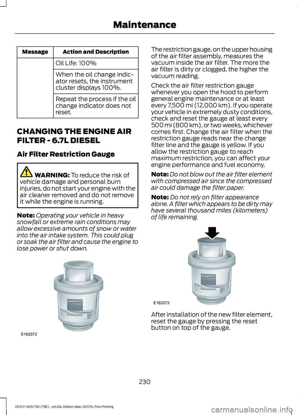
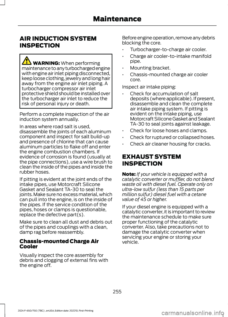
The restriction gauge, on the upper housingof the air filter assembly, measures thevacuum inside the air filter. The more theair filter is dirty or clogged, the higher thevacuum reading.
Check the air filter restriction gaugewhenever you open the hood to performgeneral engine maintenance or at leastevery 7,500 mi (12,000 km). If you operateyour vehicle in extremely dusty conditions,check and reset the gauge at least every500 mi (800 km), or two weeks, whichevercomes first. Change the air filter when therestriction gauge reads near the changefilter line and the gauge is yellow. If youallow the restriction gauge to reachmaximum restriction, you can affect yourengine performance and fuel economy.
Note:Do not blow out the air filter elementwith compressed air since the compressedair could damage the filter paper.
Note:Do not rely on filter appearancealone. A filter which appears to be dirty mayhave several thousand miles (kilometers)of life remaining.
After installation of the new filter element,reset the gauge by pressing the resetbutton on top of the gauge.
230
2024 F-650/750 (TBC) , enUSA, Edition date: 202210, First-PrintingMaintenanceE163372 E163373
Page 252 of 386

the driver that battery protection actionsare active. These messages are only fornotification that an action is taking place,and not intended to indicate an electricalproblem or that the battery requiresreplacement.
Electrical accessory installation
To ensure proper operation of the BMS,any electrical devices that are added tothe vehicle should not have their groundconnection made directly at the negativebattery post. A connection at the negativebattery post can cause inaccuratemeasurements of the battery conditionand potential incorrect system operation.
Note:Electrical or electronic accessoriesadded to the vehicle by the dealer or theowner may adversely affect batteryperformance and durability, and may alsoaffect the performance of other electricalsystems in the vehicle.
When a battery replacement is required,the battery should only be replaced witha Ford recommended replacement batterywhich matches the electrical requirementsof the vehicle. After battery replacement,or in some cases after charging the batterywith the external charger, the BMS requireseight hours of vehicle sleep time (key offwith doors closed) to relearn the newbattery state of charge. Prior to relearningthe state of charge, the BMS may disableelectrical features (to protect the battery)earlier than normal.
ADJUSTING THE HEADLAMPS
Vertical Aim Adjustment
The headlamps on your vehicle areproperly aimed at the assembly plant. Ifyour vehicle has been in an accident, thealignment of your headlamps should bechecked by your authorized dealer.
Headlamp Aiming Target
8 ft (2.4 m)A
Center height of lamp to groundB
25 ft (7.6 m)C
Horizontal reference lineD
Vertical Aim Adjustment Procedure
1.Park the vehicle directly in front of awall or screen on a level surface,approximately 25 ft (7.6 m) away.
2.Measure the height of the headlampbulb center from the ground and markan 8 ft (2.4 m) horizontal reference lineon the vertical wall or screen at thisheight.
Note:To see a clearer light pattern foradjusting, you may want to block the lightfrom one headlamp while adjusting theother.
3.Turn on the low beam headlamps toilluminate the wall or screen and openthe hood.
248
2024 F-650/750 (TBC) , enUSA, Edition date: 202210, First-PrintingMaintenanceE142592
Page 259 of 386
AIR INDUCTION SYSTEM
INSPECTION
WARNING: When performingmaintenance to any turbocharged enginewith engine air inlet piping disconnected,keep loose clothing, jewelry and long hairaway from the engine air inlet piping. Aturbocharger compressor air inletprotective shield should be installed overthe turbocharger air inlet to reduce therisk of personal injury or death.
Perform a complete inspection of the airinduction system annually.
In areas where road salt is used,disassemble the joints of each aluminumcomponent and inspect for salt build-upand presence of chlorine that can causealuminum particles to flake off and enterthe engine combustion chambers. Ifevidence of corrosion is found (usually atthe pipe connections), use a wire brush toclean the inside of the pipes and inside therubber hoses.
If pitting is evident at the joint ends of theintake pipes, use Motorcraft SiliconeGasket and Sealant TA-30 to seal thejoints. Make sure no excess material, whichcan pull into the engine, is on the inside ofthe pipes. If the service condition of thepipes, hoses or clamps is questionable,replace the defective part(s).
Make sure to clean all dust and debris outof the pipes and couplings with a clean,damp rag before reassembly.
Chassis-mounted Charge AirCooler
Visually inspect the core assembly fordebris and clogging of external fins withthe engine off.
Before engine operation, remove any debrisblocking the core.
•Turbocharger-to-charge air cooler.
•Charge air cooler-to-intake manifoldpipe.
•Mounting bracket.
•Chassis-mounted charge air coolercore.
Inspect air intake piping:
•Check for accumulation of saltdeposits (where applicable). If present,disassemble and clean the completeair intake piping system. If pitting isevident on the intake piping, useMotorcraft Silicone Gasket and SealantTA-30 to seal joints against leakage.
•Check for loose hoses and clamps.
•Check for ruptured or collapsed hoses.
•Check air cleaner housing for cracks.
EXHAUST SYSTEM
INSPECTION
Note:If your vehicle is equipped with acatalytic converter or muffler, do not blendwaste oil with diesel fuel. Operate only onultra-low sulfur (less than 15 parts permillion sulfur) diesel fuel with a cetanevalue of 45 or higher.
If your diesel engine is equipped with acatalytic converter, it is important to reviewthe maintenance schedule to make sureproper functioning of the catalyticconverter. Also, take precautions not todamage the catalytic converter whenservicing your engine or storing yourvehicle.
255
2024 F-650/750 (TBC) , enUSA, Edition date: 202210, First-PrintingMaintenance
Page 264 of 386

•Maintaining proper steering gear andpower steering pump lubricant levels.
•Checking steering column joint boltsand steering linkage, particularly forbody-to-chassis clearance.
Steering Column Joint Bolts
As a good maintenance practice, checksteering column joint bolt tightness every60,000 mi (96,000 km) or annually,whichever occurs first. Do not overtightenthe bolts.
Hydraulic System
Whenever draining and refilling the powersteering's hydraulic system for any reason,bleed air from the system before returningthe vehicle to service. Failure to bleed thehydraulic system properly can result indegradation of power system performance.
Consult an authorized dealer who is awareof the proper procedures for filling andbleeding the system.
SUSPENSION SYSTEM
INSPECTION (IF EQUIPPED)
Note:Do not adjust air suspension heightto any setting other than the specifiedsetting. Altering the height setting changesthe driveline angle and may result inunwarrantable component damage, suchas transmission component damage.
Verify drive axle air suspension height andheight control valve performance at engineoil change intervals.
Periodically check:
•Condition of spring leaves for evidenceof fatigue, bending or breakage.
•Condition of suspension mountingbrackets and bushings.
•Torque rod mounting fasteners fortightness.
•For proper suspension alignment.Maintain proper alignment at all times.
•U-bolts. After the chassis has beenoperating under load for 1,000 mi(1,600 km) or six months (whichevercomes first), the U-bolt nuts must bere-torqued. Re-torque the U-bolt nutsevery 37,000 mi (60,000 km)thereafter. Clean and lubricate theU-bolt and nut threads and seats tomake sure a like new condition whenre-torqueing. See Spring U-BoltCheck (page 261).
FRAME AND TOW HOOK
INSPECTION
Your vehicle's chassis is manufacturedwith frame rails of either HSLA steel orheat-treated steel. Handle each in aspecific manner to make sure maximumservice life. Consult the service manual oran authorized dealer before attemptingframe repair or modification.
It is important, particularly on vehicles thatuse tow hooks frequently, to inspect thefront and rear tow hooks for damage or aloose mounting.
REAR AXLE FLUID CHECK
Your rear axle may have an optionalsynthetic lubricant that allows the use ofextended service intervals. A tag on thefiller plug identifies the use of the syntheticlubricant.
Only use a lubricant that meetsmanufacturer specifications. Use of anon-approved rear axle lubricant maycause internal axle component damage.See Rear Axle Fluid Capacity andSpecification (page 311).
Checking the Fluid Level
1.Park your vehicle on level ground.
260
2024 F-650/750 (TBC) , enUSA, Edition date: 202210, First-PrintingMaintenance
Page 272 of 386
Cooling system
•Protect against freezing temperatures.
•When removing your vehicle fromstorage, check coolant fluid level.Confirm that there are no coolingsystem leaks and that fluid is at therecommended level.
Disconnecting Your 12 Volt Battery
•Check and recharge as necessary. Keepconnections clean.
•If storing your vehicle for more than 30days without recharging the battery,we recommend that you disconnectthe battery cables to maintain batterycharge for quick starting.
Note:It is necessary to reset memoryfeatures if you disconnect the batterycables.
Brakes
•Make sure the brakes and parking brakerelease fully.
Tires
•Maintain recommended air pressure.
Miscellaneous
•Make sure all linkages, cables, leversand pins under your vehicle are coveredwith grease to prevent rust.
•Move vehicles at least 25 ft (7.5 m)every 15 days to lubricate working partsand prevent corrosion.
Removing Vehicle From Storage
When your vehicle is ready to come out ofstorage, do the following:
•Wash your vehicle to remove any dirtor grease film build-up on windowsurfaces.
•Check windshield wipers for anydeterioration.
•Check under the hood for any foreignmaterial that may have collectedduring storage such as mice or squirrelnests.
•Check the exhaust for any foreignmaterial that may have collectedduring storage.
•Check tire pressures and set tireinflation per the Tire Label.
•Check brake pedal operation. Driveyour vehicle 15 ft (4.5 m) back andforth to remove rust build-up.
•Check fluid levels (including coolant,oil and gas) to make sure there are noleaks, and fluids are at recommendedlevels.
•If you remove the battery, clean thebattery cable ends and check fordamage.
Contact an authorized dealer if you haveany concerns or issues.
268
2024 F-650/750 (TBC) , enUSA, Edition date: 202210, First-PrintingVehicle Care
Page 331 of 386
Scheduled Maintenance Services
Maintenance service adjustments mustconform to specifications contained in thismanual, and those shown on the ImportantEngine Information decal. Perform thefollowing services at scheduled intervalsbecause they essential to the life andperformance of your vehicle. Fordrecommends that you performmaintenance on all designated items toachieve best vehicle operation.
There are three types of maintenanceintervals for general vehicle environments:On-Highway, City and Severe Service. Inall applications, monitoring miles(kilometers) and time and when the engineis due for an oil change determine theactual interval. When the engine oil changeis required before the truck lubricationinterval, perform the lubrication at thesame time in order to reduce your vehicle’stime out of service.
Air Brake Adjustment
WARNING: Failure to maintainproper air brake adjustment can resultin reduction or loss of braking ability.
A qualified service technician, keeping tothe instructions in the service manual,should perform air brake inspection andadjustment or repairs.
Cam Brakes - Automatic SlackAdjusters
WARNING: Do not manually adjustthe automatic slack adjusters to correctexcessive push rod stroke as it may resultin reduced brake effectiveness and avehicle crash. Excessive push rod strokeindicates that a problem exists with theautomatic adjuster, with the installationof the adjuster, or with foundation brakecomponents that manual adjustmentdoes not remedy. Seek service from aqualified facility for excessive push rodstroke.
Inspect standard air brakes equipped withautomatic slack adjusters for proper brakeadjustment as listed in the maintenanceschedule charts.
However, inspect the brakes morefrequently when subjecting them to heavyuse or adverse operating conditions suchas:
•Frequent brake applications while fullyloaded.
•Operation on hilly or mountainousterrain.
•Frequent operation on dirt, gravel ormud.
Some aftermarket brake linings alsorequire more frequent inspections.
Owner Checks and Services
Make sure you perform the following basicmaintenance checks and inspections everymonth or at six-month intervals.
327
2024 F-650/750 (TBC) , enUSA, Edition date: 202210, First-PrintingScheduled Maintenance
Page 332 of 386
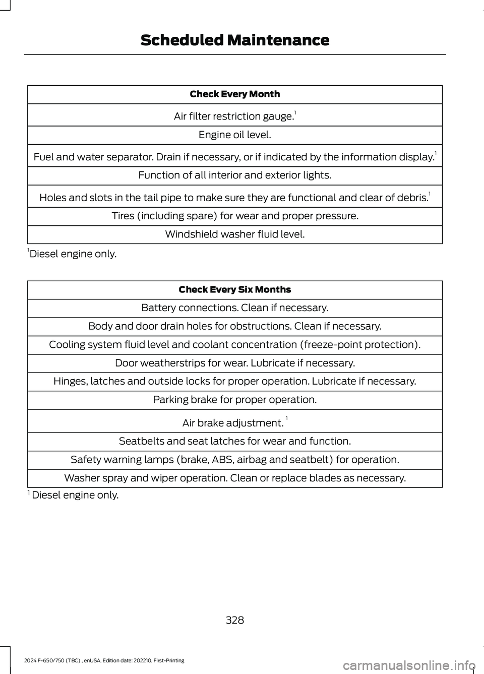
Check Every Month
Air filter restriction gauge.1
Engine oil level.
Fuel and water separator. Drain if necessary, or if indicated by the information display.1
Function of all interior and exterior lights.
Holes and slots in the tail pipe to make sure they are functional and clear of debris.1
Tires (including spare) for wear and proper pressure.
Windshield washer fluid level.
1Diesel engine only.
Check Every Six Months
Battery connections. Clean if necessary.
Body and door drain holes for obstructions. Clean if necessary.
Cooling system fluid level and coolant concentration (freeze-point protection).
Door weatherstrips for wear. Lubricate if necessary.
Hinges, latches and outside locks for proper operation. Lubricate if necessary.
Parking brake for proper operation.
Air brake adjustment.1
Seatbelts and seat latches for wear and function.
Safety warning lamps (brake, ABS, airbag and seatbelt) for operation.
Washer spray and wiper operation. Clean or replace blades as necessary.
1 Diesel engine only.
328
2024 F-650/750 (TBC) , enUSA, Edition date: 202210, First-PrintingScheduled Maintenance