2023 TOYOTA PRIUS PRIME ECU
[x] Cancel search: ECUPage 578 of 680

5788-2. Steps to take in an emergency
ble.
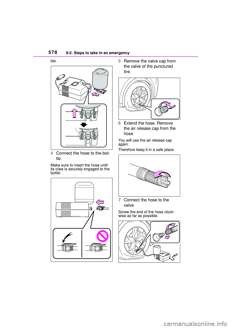
4Connect the hose to the bot-
tle.
Make sure to insert the hose until
its claw is securely engaged to the
bottle.
5Remove the valve cap from
the valve of the punctured
tire.
6 Extend the hose. Remove
the air release cap from the
hose.
You will use the air release cap
again.
Therefore keep it in a safe place.
7Connect the hose to the
valve.
Screw the end of the hose clock-
wise as far as possible.
Page 582 of 680

5828-2. Steps to take in an emergency
dealer.
When having the tire repaired or
replaced, make sure to tell your
Toyota dealer that the sealant is
injected.
■If the tire is inflated to more
than the specified air pressure
1 Disconnect the hose from the
valve.
2 Install the air release cap to the
end of the hose and push the
protrusion on the air release cap
into the tire valve to let some air
out.
3 Disconnect the hose from the
valve, remove the air release cap
from the hose and then recon-
nect the hose.
4 Turn the compressor switch on
and wait for several seconds,
and then turn it off. Check that
the air pressure indicator shows
the specified air pressure.
If the air pressure is under the des-
ignated pressure, turn the compres-
sor switch on again and repeat the
inflation procedure until the speci-
fied air pressure is reached.
■After a tire is repaired with the
emergency tire puncture repair
kit
●The tire pressure warning valve
and transmitter should be
replaced.
●Even if the tire inflation pressure is
at the recommended level, the tire
pressure warning light may come
on/flash.
WARNING
■When fixing the flat tire
●Stop your vehicle in a safe and
flat area.
●Do not touch the wheels or the
area around the brakes immedi-
ately after the vehicle has been
driven.
After the vehicle has been
driven, the wheels and the area
around the brakes may be
extremely hot. Touching these
areas with hands, feet or other
body parts may result in burns.
●Connect the valve and hose
securely with the tire installed
on the vehicle. If the hose is not
properly connected to the valve,
air leakage may occur as seal-
ant may be sprayed out.
●If the hose comes off the valve
while inflating the tire, there is a
risk that the hose will move
abruptly due to air pressure.
●After inflation of the tire has
completed, the sealant may
splatter when the hose is dis-
connected or some air is let out
of the tire.
●Follow the operation procedure
to repair the tire. If the proce-
dures not followed, the sealant
may spray out.
●Keep back from the tire while it
is being repaired, as there is a
chance of it bursting while the
repair operation is being per-
formed. If you notice any cracks
or deformation of the tire, turn
off the compressor switch and
stop the repair operation imme-
diately.
Page 591 of 680

5918-2. Steps to take in an emergency
8
When trouble arises
cal components when the vehicle
is running at a low speed for an
extended period, such as in heavy
traffic.
■When the 12-volt battery is
removed or discharged
●Information stored in the ECU is
cleared. When the 12-volt battery
is depleted, have the vehicle
inspected at your Toyota dealer.
●Some systems may require initial-
ization. ( P.634)
■When removing the 12-volt bat-
tery terminals
When the 12-volt battery terminals
are removed, the information stored
in the ECU is cl eared. Before
removing the 12-volt battery termi-
nals, contact your Toyota dealer.
■Charging the 12-volt battery
The electricity stored in the 12-volt
battery will discharge gradually even
when the vehicle is not in use, due
to natural discharge and the drain-
ing effects of certain electrical appli-
ances. If the vehicle is left for a long
time, the 12-volt battery may dis-
charge, and the hybrid system may
be unable to start. (The 12-volt bat-
tery recharges automatically while
the hybrid system is operating.)
■When recharging or replacing
the 12-volt battery
●In some cases, it may not be pos-
sible to unlock the doors using the
smart key system when the 12-
volt battery is discharged. Use the
wireless remote control or the
mechanical key to lock or unlock
the doors.
●The hybrid system may not start
on the first attemp t after reinstall-
ing the 12-volt battery. In that
case, start the hybrid system in
the same manner as when the
electronic key does not operate
properly ( P.588). This is not a
malfunction, as the hybrid system
will start normally on the second
attempt.
●The power switch mode is memo-
rized by the vehicle. When the 12-
volt battery is reconnected, the
system will return to the mode it
was in before the 12-volt battery
was discharged. Before discon-
necting the 12-volt battery, turn
the power switch off.
If you are unsure what mode the
power switch was in before the
12-volt battery discharged, be
especially careful when recon-
necting the 12-volt battery.
●If the 12-volt battery discharges, it
may not be possible to shift the
shift position to other positions.
In this case, the vehicle can not be
towed without lifting both front
wheels because the front wheels
will be locked.
●Some systems may require initial-
ization. ( P.634)
■When replacing the 12-volt bat-
tery
●Use a 12-volt battery that con-
forms to Europ ean regulations.
●Use a battery that the case size is
same as the previous one (LN1),
20 hour rate capacity (20HR) is
equivalent (45Ah) or greater, and
performance rating (CCA) is
equivalent (285A) or greater.
• If the sizes differ, the 12-volt bat-
tery cannot be properly secured.
• If the 20 hour rate capacity is low, even if the time period where the
vehicle is not used is a short time,
the 12-volt battery may discharge
and hybrid system may not be
able to start.
●Use a ventilation type calcium bat-
tery
●Use a 12-volt battery with a han-
dle. If a 12-volt battery without a
handle is used, removal is more
difficult.
●When removing the 12-volt bat-
tery: P.512
●After replacing, firmly attach the
following items to the exhaust hole
Page 593 of 680

5938-2. Steps to take in an emergency
8
When trouble arises
WARNING
●Always wash your hands after
handling the 12-volt battery sup-
port, terminals, and other bat-
tery-related parts.
●Do not allow children near the
12-volt battery.
■After recharging the 12-volt
battery
Have the 12-volt battery
inspected at your Toyota dealer
as soon as possible.
If the 12-volt batter y is deteriorat-
ing, continued use may cause the
12-volt battery to emit a malodor-
ous gas, which may be detrimen-
tal to the health of passengers.
■When replacing the 12-volt
battery
●For information regarding 12-
volt battery replacement, con-
tact your Toyota dealer.
●After replacing, securely attach
the exhaust hose and exhaust
hole plug to the exhaust hole of
the replaced 12-volt battery. If
not properly installed, gases
(hydrogen) may leak into the
vehicle interior, and there is the
possible danger of the gas ignit-
ing and exploding.
NOTICE
■When handling jumper cables
When connecting the jumper
cables, ensure that they do not
become entangled in the cooling
fan, etc.
■When connecting jumper
cables
Make sure to connect jumper
cables to the specified terminals
and connecting point. Failure to
do so may adversely affect the
electronic devices or damage to
them.
■To prevent damaging the
vehicle
The exclusive jump starting termi-
nal is to be used when charging
the 12-volt battery from another
vehicle in an emergency. It cannot
be used to jump start another
vehicle.
Page 617 of 680

6179-1. Specifications
9
Vehicle specifications
*: Table 1 Occupant loading and distributio n for vehicle normal load for
various designated seating capacities
Snow tire
A tire that attains a traction index equal to or
greater than 110, compared to the ASTM E-
1136 Standard Reference Test Tire, when using
the snow traction test as described in ASTM F-
1805-00, Standard Test Method for Single
Wheel Driving Traction in a Straight Line on
Snow-and Ice-Covered Surfaces, and which is
marked with an Alpine Symbol ( ) on at least
one sidewall
Test rim
The rim on which a tire is fitted for testing, and
may be any rim listed as appropriate for use
with that tire
TreadThat portion of a tire that comes into contact
with the road
Tread ribA tread section running circumferentially around
a tire
Tread separationPulling away of the tread from the tire carcass
Treadwear indicators
(TWI)The projections within the principal grooves
designed to give a visual indication of the
degrees of wear of the tread
Wheel-holding fixtureThe fixture used to hold the wheel and tire
assembly securely during testing
Designated seating
capacity, Number of occupantsVehicle normal load,
Number of occupantsOccupant distribution in a normally loaded vehi- cle
2 through 422 in front
5 through 1032 in front, 1 in second seat
11 through 155
2 in front, 1 in second
seat, 1 in third seat, 1 in fourth seat
16 through 207
2 in front, 2 in second
seat, 2 in third seat, 1 in fourth seat
Tire related termMeaning
Page 623 of 680

6239-2. Customization
9
Vehicle specifications
*1: This setting changes in accordance with My Settings.
*2: This setting can be changed when the smart door unlocking setting is set
to Driver’s door.
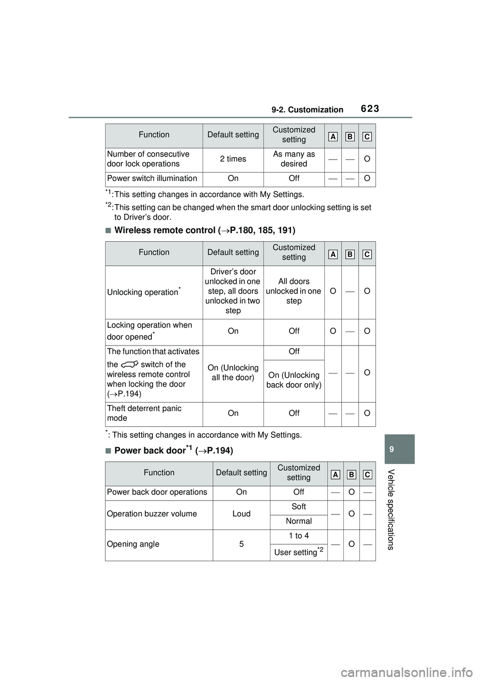
■Wireless remote control ( P.180, 185, 191)
*: This setting changes in accordance with My Settings.
■Power back door*1 ( P.194)
Number of consecutive
door lock operations2 timesAs many as
desiredO
Power switch illuminationOnOffO
FunctionDefault settingCustomized setting
Unlocking operation*
Driver’s door
unlocked in one step, all doors
unlocked in two step
All doors
unlocked in one step
OO
Locking operation when
door opened
*OnOffOO
The function that activates
the switch of the
wireless remote control
when locking the door
( P.194)
On (Unlocking
all the door)
Off
OOn (Unlocking
back door only)
Theft deterrent panic
modeOnOffO
FunctionDefault settingCustomized setting
Power back door operationsOnOffO
Operation buzzer volumeLoudSoftONormal
Opening angle5
1 to 4
O
User setting*2
FunctionDefault settingCustomized settingABC
ABC
ABC
Page 637 of 680

63710-1. For owners
10
For owners
Tirez sur la ceinture épau-
lière jusqu’à ce qu’elle recou-
vre entièrement l’épaule; elle
ne doit cependant pas
toucher le cou ni glisser de
l’épaule.
Placez la ceinture abdominale
le plus bas possible sur les
hanches.
Réglez la position du dossier.
Tenez-vous assis bien au
fond du siège, le dos droit.
Ne vrillez pas la ceinture de
sécurité.
Reporting safety
defects for Canadian
owners
Canadian customers who
wish to report a safety-
related defect to Transport
Canada, Defects Investiga-
tions and Recalls, may tele-
phone the toll-free hotline 1-
800-333-0510, mail Trans-
port Canada - ASFAD, 330
Sparks Street, Ottawa, ON,
K1A 0N5, or complete the
online form at
https://www.tc.gc.ca/recalls .
Seat belt instructions
for Canadian owners
(in French)
The following is a French
explanation of seat belt
instructions extracted from
the seat belt section in this
manual.
See the seat belt section for
more detailed seat belt
instructions in English.
Utilisation adéquate des
ceintures de sécurité
Page 638 of 680

63810-1. For owners
■Manipulation des ceintures
de sécurité
Avec un chiffon ou une éponge,
nettoyez à l’aide d’un savon
doux et de l’eau tiède. Vérifiez
aussi les ceintures régulière-
ment pour vous assurer qu’elles
ne présentent pas d’usure
excessive, d’effilochage ou de
coupures.
Entretien et soin
AVERTISSEMENT
■Dommages et usure de la
ceinture de sécurité
Vérifiez périodiquement le sys-
tème de ceintures de sécurité.
Vérifiez qu’il n’y a pas de cou-
pures, d’effilochures ni de pièces
desserrées. N’utilisez pas une
ceinture de sécurité endommagée
avant qu’elle ne soit remplacée.
Les ceintures de sécurité endom-
magées ne peuvent pas protéger
les occupants contre les bless-
ures graves, voire mortelles.