2023 NISSAN PATHFINDER ESP
[x] Cancel search: ESPPage 255 of 665

TROUBLESHOOTING GUIDE
Verif y the location of all Intelligent Keys that
are programmed for the vehicle. If another
Intelligent Key is in range or inside the ve-
hicle, the vehicle system may respond dif-
ferently than expected.
SymptomPossible CauseRemedy
When shif ting the shif t position to the
P (Park) position The Push ignition to OFF warning ap-
pears in the display. The ignition switch is in the ACC or ON
position.Place the ignition switch in the OFF
position.
When opening the driver's door to get
out of the vehicle The Door/Lif tgate Open warning ap-
pears on the display and the inside
warning chime sounds continuously. The ignition switch is in the ACC or ON
position.
Place the ignition switch in the OFF
position.
When closing the door af ter getting
out of the vehicle The No Key Detected warning appears
on the display, the outside chime
sounds three times and the inside
warning chime sounds for approxi-
mately 3 seconds.
The ignition switch is in the ACC or ON
position.
Place the ignition switch in the OFF
position.
The Rear Door Alert warning message
appears on the display, the horn
sounds three times twice, or a “Check
Rear Seat For All Articles” warning ap-
pears on the display. The Rear Door Alert is activated.
Check the back seat for all articles,
press the OK button to clear the Rear
Door Alert warning message.
When closing the door with the inside
lock knob turned to LOCK The outside chime sounds for approxi-
mately 3 seconds and all the doors
unlock.
The Intelligent Key is inside the vehicle. Carry the Intelligent Key with you.
When touching the door handle lock
sensor or the
button on the In-
telligent Key to lock the door The outside chime sounds for approxi-
mately 2 seconds.
The Intelligent Key is inside the vehicle. Carry the Intelligent Key with you.
3-18Pre-driving checks and adjustments
Page 275 of 665

NOTE:
Do not hang any objects over the sen-
sors
O1or apply glass cleaner to the sen-
sors. Doing so will reduce the sensitivity
of the sensors, resulting in improper
operation.
For additional information on HomeLink®
Universal Transceiver operation, see
“HomeLink® Universal Transceiver”
(P. 2-125).
OUTSIDE MIRRORS
The outside mirror remote control will op-
erate only when the ignition switch is in the
ACC or ON position.
Push the switch
O1orO2to select the lef t
or right mirror. Adjust each mirror to the
desired position using the large switch
O3.
Push the switch
O1orO2and make sure
that the corresponding light is off, to pre-
vent accidentally moving the mirror.
WARNING
• Objects viewed in the outside mirror
on the passenger side are closer than
they appear. Be careful when moving
to the right. Using only this mirror
could cause an accident. Use the in-
side mirror or glance over your
shoulder to properly judge distances
to other objects.
• Do not adjust the mirrors while driv-
ing. You could lose control of your ve-
hicle and cause an accident.
LPD3166
3-38Pre-driving checks and adjustments
Page 276 of 665
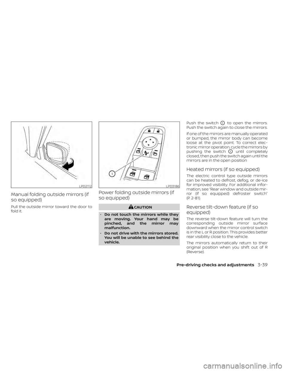
Manual folding outside mirrors (if
so equipped)
Pull the outside mirror toward the door to
fold it.
Power folding outside mirrors (if
so equipped)
CAUTION
• Do not touch the mirrors while they
are moving. Your hand may be
pinched, and the mirror may
malfunction.
• Do not drive with the mirrors stored.
You will be unable to see behind the
vehicle. Push the switch
O1to open the mirrors.
Push the switch again to close the mirrors.
If one of the mirrors are manually operated
or bumped, the mirror body can become
loose at the pivot point. To correct elec-
tronic mirror operation, cycle the mirrors by
pushing the switch
O1until completely
closed, then push the switch again until the
mirrors are in the open position
Heated mirrors (if so equipped)
The electric control type outside mirrors
can be heated to defrost, defog, or de-ice
for improved visibility. For additional infor-
mation, see “Rear window and outside mir-
ror (if so equipped) defroster switch”
(P. 2-81).
Reverse tilt-down feature (if so
equipped)
The reverse tilt-down feature will turn the
corresponding outside mirror surface
downward when the mirror control switch
is in the L or R position. This provides better
rear visibility close to the vehicle.
The mirrors automatically return to their
original position when you shif t out of R
(Reverse).
LPD2112LPD3186
Pre-driving checks and adjustments3-39
Page 278 of 665
5. Within the settings menu of the touchscreen display, select “Edit User” and
then “User Profiles”.
6. Create a personal profile and make sure the correct key number is selected with
the arrow.
7. Set the desired seat, steering and mirror positions.
8. Place the ignition switch in the OFF po- sition and lock the vehicle with the Intel-
ligent Key.
Once Step 8 is completed, every time the
vehicle is unlocked using the Intelligent Key
and the ignition is switched placed in the
ON position, the memory positions will be
recalled.
For additional information, see the
“NissanConnect® Owner’s Manual.
Follow the same procedure if you want
to link the 2nd, 3rd or 4th Intelligent Key.
NOTE:
If new memory positions are set prior to
turning the ignition from ON to OFF, the
previously linked memory positions for
the respective key will be overwritten by
new positions.
Recalling Intelligent Key memory
positions
If the “Key-Linked Settings” are enabled in
the vehicle information display for that par-
ticular key, every time you enter the vehicle
the driver’s seat, automatic steering wheel,
and outside mirrors will automatically
move to the driver’s last position of the
respective Intelligent Key.
NOTE:
The key-linked memory positions can be
different from the positions stored in the
memory switch (1 or 2).
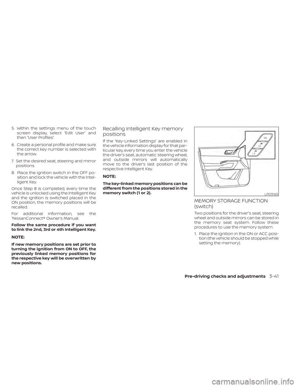
MEMORY STORAGE FUNCTION
(switch)
Two positions for the driver's seat, steering
wheel and outside mirrors can be stored in
the memory seat system. Follow these
procedures to use the memory system.
1. Place the ignition in the ON or ACC posi- tion (the vehicle should be stopped while
setting the memory).
LPD3165
Pre-driving checks and adjustments3-41
Page 279 of 665
2. Adjust the driver's seat, steering wheeland outside mirrors to the desired posi-
tions by manually operating each ad-
justing switch. For additional informa-
tion, see “Seats” (P. 1-2), “Steering wheel”
(P. 3-34) and “Outside mirrors” (P. 3-38).
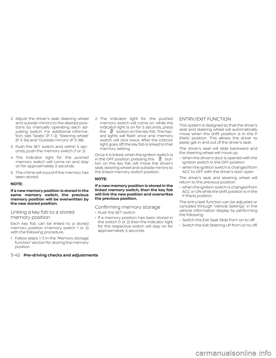
3. Push the SET switch and, within 5 sec- onds, push the memory switch (1 or 2).
4. The indicator light for the pushed memory switch will come on and stay
on for approximately 5 seconds.
5. The chime will sound if the memory has been stored.
NOTE:
If a new memory position is stored in the
same memory switch, the previous
memory position will be overwritten by
the new stored position.
Linking a key fob to a stored
memory position
Each key fob can be linked to a stored
memory position (memory switch 1 or 2)
with the following procedure.
1. Follow steps 1-3 in the “Memory storagefunction” section for storing the memory
position. 2. The indicator light for the pushed
memory switch will come on. While the
indicator light is on for 5 seconds, press
the
button on the key fob. The haz-
ard lights will flash once and memory
switch will click twice. Af ter the indictor
light goes off, the key fob is linked to that
memory setting.
Once it is linked, when the ignition switch is
in the OFF position, pressing the
but-
ton on the key fob will move the driver’s
seat, steering wheel and outside mirrors to
the linked memory switch position.
NOTE:
If a new memory position is stored in the
linked memory switch, then the key fob
will link the new position and overwrites
the previous position.
Confirming memory storage
• Push the SET switch.
• If a memory position has been stored in the switch (1 or 2) then the indicator light
for the respective switch will stay on for
approximately 5 seconds.
ENTRY/EXIT FUNCTION
This system is designed so that the driver's
seat and steering wheel will automatically
move when the shif t position is in the P
(Park) position. This allows the driver to
easily get in and out of the driver’s seat.
The driver’s seat will slide backward and
the steering wheel will move up:
• When the driver’s door is opened with theignition switch in the OFF position.
• When the ignition switch is changed from ACC to OFF with the driver’s door open.
The driver’s seat and steering wheel will
return to the previous position:
• When the ignition switch is changed from ACC or ON while the shif t position is in the
P (Park) position.
The entry/exit function can be adjusted or
canceled through “Vehicle Settings” in the
vehicle information display by performing
the following:
• Switch the Exit Seat Slide from on to off.
• Switch the Exit Steering UP from on to off.
3-42Pre-driving checks and adjustments
Page 292 of 665
WARNING
• Failure to follow the warnings and in-
structions for the proper use of the
Intelligent Around View® Monitor
system could result in serious injury
or death.
• The Intelligent Around View® Monitor
is a convenience feature and is not a
substitute for proper vehicle opera-
tion because it has areas where ob-
jects cannot be viewed. The four cor-
ners of the vehicle in particular, are
areas where objects do not always
appear in the bird’s-eye, front, or rear
views. Always check your surround-
ings to be sure that it is safe to move
before operating the vehicle. Always
operate the vehicle slowly.
• The driver is always responsible for
safety during parking and other
maneuvers.
CAUTION
Do not scratch the camera lens when
cleaning dirt or snow from the front of
the camera. The Intelligent Around View® Monitor sys-
tem is designed as an aid to the driver in
situations such as slot parking or parallel
parking.
The monitor displays various views of the
position of the vehicle in a split screen for-
mat. Not all views are available at all times.
Available views:
• Front View
A view of the front of the vehicle.
• Rear View A view of the rear of the vehicle.
• Bird's-Eye View The surrounding view of the vehicle from
above.
• Front-Side View The view around and ahead of the front
passenger's side wheel.
• Front-Wide View A wider area view of the front view.
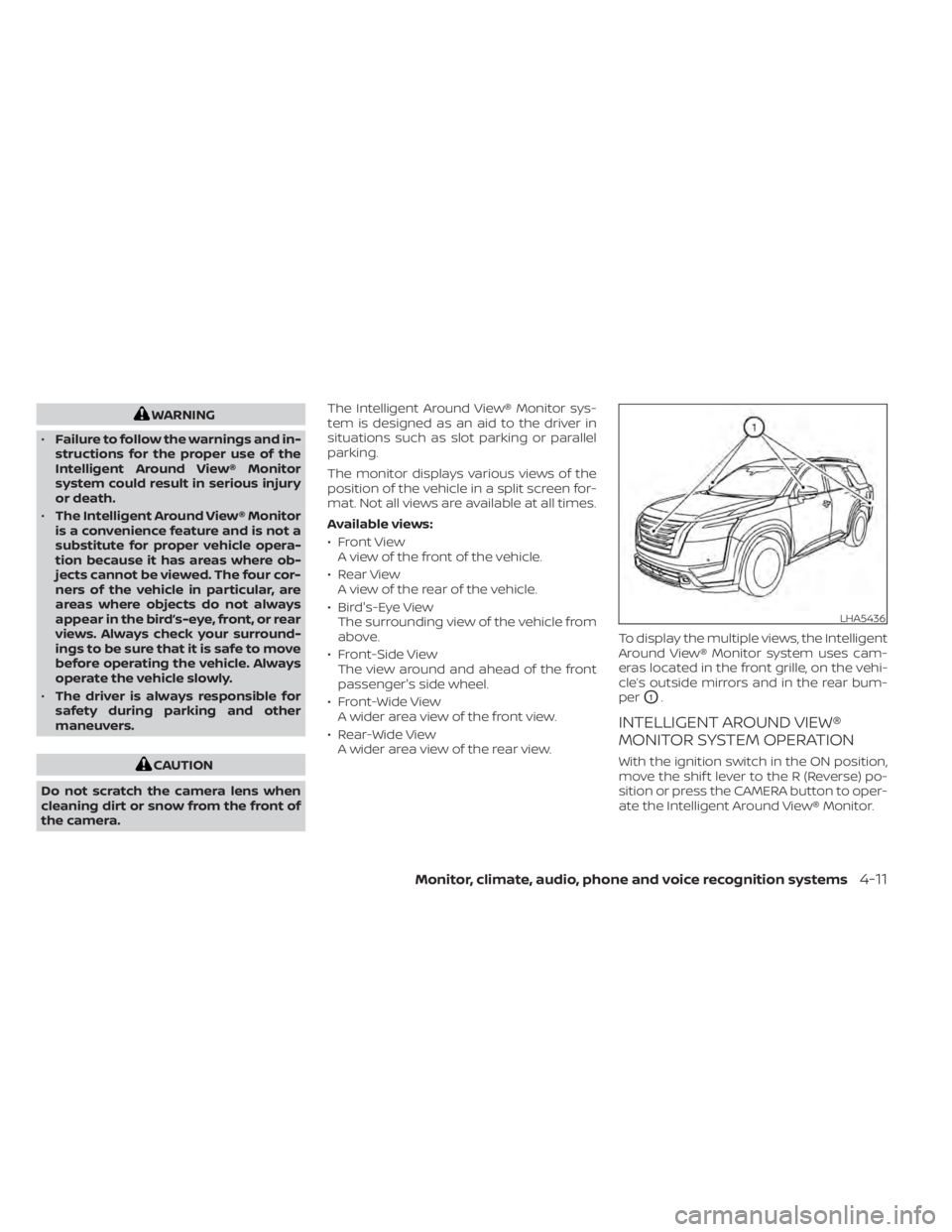
• Rear-Wide View A wider area view of the rear view. To display the multiple views, the Intelligent
Around View® Monitor system uses cam-
eras located in the front grille, on the vehi-
cle’s outside mirrors and in the rear bum-
per
O1.
INTELLIGENT AROUND VIEW®
MONITOR SYSTEM OPERATION
With the ignition switch in the ON position,
move the shif t lever to the R (Reverse) po-
sition or press the CAMERA button to oper-
ate the Intelligent Around View® Monitor.
LHA5436
Monitor, climate, audio, phone and voice recognition systems4-11
Page 304 of 665

WARNING
Failure to follow the warnings and in-
structions for proper use of the sonar
function as outlined in this section
could result in serious injury or death.
• The sonar is a convenience feature. It
is not a substitute for proper parking.
• This function is designed as an aid to
the driver in detecting large station-
ary objects to help avoid damaging
the vehicle.
• The driver is always responsible for
safety during parking and other
maneuvers.
• Always look around and check that it
is safe to move before parking.
• Read and understand the limitations
of the sonar as contained in this
section.
The sonar function helps to inform the
driver of large stationary objects around
the vehicle when parking by issuing an au-
dible and visual alert.
SONAR SYSTEM OPERATION
1. Center display
2. MENU button
3. CAMERA button The system gives the tone for rear objects
when the shif t lever is in the “R” (Reverse)
position.
When the camera image is shown on the
center display, the system shows the sonar
indicator regardless of the shif t lever
position.
LHA5480
CAMERA AIDING SONAR (parking
sensor) (if so equipped)
Monitor, climate, audio, phone and voice recognition systems4-23
Page 321 of 665
When installing a CB, ham radio or car
phone in your vehicle, be sure to observe
the following precautions; otherwise, the
new equipment may adversely affect the
engine control system and other electronic
parts.
WARNING
• A cellular phone should not be used
for any purpose while driving so full
attention may be given to vehicle op-
eration. Some jurisdictions prohibit
the use of cellular phones while
driving.
• If you must make a call while your
vehicle is in motion, the hands free
cellular phone operational mode is
highly recommended. Exercise ex-
treme caution at all times so full at-
tention may be given to vehicle
operation.
• If you are unable to devote full atten-
tion to vehicle operation while talk-
ing on the phone, pull off the road to
a safe location and stop your vehicle.
CAUTION
• Keep the antenna as far away as pos-
sible from the electronic control
modules.
• Keep the antenna wire more than 8 in
(20 cm) away from the electronic
control system harnesses. Do not
route the antenna wire next to any
harness.
• Adjust the antenna standing-wave
ratio as recommended by the
manufacturer.
• Connect the ground wire from the CB
radio chassis to the body.
• For additional information, it is rec-
ommended that you visit a NISSAN
dealer for servicing. “Made for iPod”, “Made for iPhone” and
“Made for iPad” mean that an electronic
accessory has been designed to connect
specifically to iPod, iPhone or iPad, respec-
tively, and has been certified by the devel-
oper to meet Apple performance stan-
dards. Apple is not responsible for the
operation of this device or its compliance
with safety and regulatory standards.
Please note that the use of this accessory
with iPod, iPhone or iPad may affect wire-
less performance.
iPad, iPhone, iPod classic, iPod nano, iPod
shuffle and iPod touch are trademarks of
Apple Inc., registered in the U.S. and other
countries. Lightning is a trademark of
Apple Inc.
CAR PHONE OR CB RADIO
iPod®/iPhone®
4-40Monitor, climate, audio, phone and voice recognition systems