2023 NISSAN PATHFINDER ESP
[x] Cancel search: ESPPage 206 of 665
– It may not be possible to make anemergency call depending on the
severity of a collision and/or
emergency.
• Park the vehicle in a safe location and
set the parking brake before operat-
ing the Emergency Call (SOS) button.
• Only use this service in case of an
emergency. There may be a penalty
for inappropriate use of the service.
• Radio waves could adversely affect
electric medical equipment. Indi-
viduals who use a pacemaker should
contact the device manufacturer re-
garding any possible effects before
using the system.
• The TCU (Telematics Control Unit) an-
tenna is installed inside the upper
central part of the instrument panel.
An occupant should not get any
closer to the antenna than specified
by the pacemaker manufacturer. The
radio waves from the TCU antenna
may adversely affect the operation
of the pacemaker while using the
NissanConnect® Services.
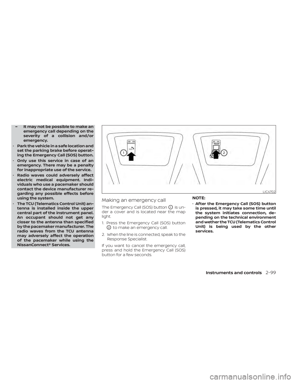
Making an emergency call
The Emergency Call (SOS) buttonO1is un-
der a cover and is located near the map
light.
1. Press the Emergency Call (SOS) button
O2to make an emergency call.
2. When the line is connected, speak to the Response Specialist.
If you want to cancel the emergency call,
press and hold the Emergency Call (SOS)
button for a few seconds.
NOTE:
• Af ter the Emergency Call (SOS) button
is pressed, it may take some time until
the system initiates connection, de-
pending on the technical environment
and wether the TCU (Telematics Control
Unit) is being used by the other
services.
LIC4702
Instruments and controls2-99
Page 207 of 665

•An indicator light on the Emergency
call (SOS) button shows the readiness
of the emergency support system. If
the indicator light is not illuminated,
pressing the Emergency Call (SOS) but-
ton does not connect your vehicle to
the Response Specialist. The indicator
light blinks while connected to the
NissanConnect® Services Response
Center.
• Even when the indicator light is illumi-
nated, connection to the
NissanConnect® Services Response
Center may not be possible. If this oc-
curs in an emergency situation, con-
tact the authorities by other means.
• To avoid disconnecting the line, keep
the engine running during an emer-
gency call, if it is safe to do so. The Rear Door Alert system functions un-
der certain conditions to indicate there
may be an object or passenger in the rear
seat(s). Check the seat(s) before exiting the
vehicle.
The Rear Door Alert system is initially dis-
abled. The driver can enable the system
using the vehicle information display. For
additional information, see “Vehicle infor-
mation display–7 inch (18 cm) Type A”
(P. 2-23) or “Vehicle information display—12.3
inch (31 cm) Type B” (P. 2-48).
When the system is enabled:
• The system is activated when a rear door
is opened and closed within 10 minutes of
the vehicle being driven. When the driver
door is closed and the system is acti-
vated, a visual message appears in the
vehicle information display. For additional
information, see “Rear Door Alert is acti-
vated” (P. 2-66).
• If a rear door is opened and closed but the vehicle is not driven within approxi-
mately 10 minutes, the system will not be
activated. A rear door must be opened
and closed and the car driven within 10
minutes for the system to activate. When the Rear Door Alert system is acti-
vated:
• When the driver puts the vehicle in the P
(Park) position, a notification message
appears in the vehicle information dis-
play with the options to “Dismiss Mes-
sage” or “Disable Alert” if desired.• Select “Disable Alert” to temporarily disable for that stop.
• No selection or ‘Dismiss Message” will keep the alert enabled for that stop.
• If the alert is enabled when a driver exits the vehicle, a message will appear in the
vehicle information display that states
“Check Back Seat For All Articles.”
If “Horn & Alert” setting is selected:
• An audible horn sound will occur af ter a short time unless a rear door is
opened and closed within a short time
to deactivate the alert.
• If the doors are locked before the alert is deactivated by opening a rear door,
the horn will sound.
• If the lif tgate is opened before a rear door is opened, the horn will be de-
layed until af ter the lif tgate is closed.
REAR DOOR ALERT
2-100Instruments and controls
Page 213 of 665
•Depending on the type of the smart-
phone, the indicator may remain illu-
minated in orange even when the
charging process has been completed.
FCC ID: BEJWC500MNM
IC: 2703H-WC500MNM
This device complies with part 15 of the
FCC Rules and RSS-Gen of IC Rules.
Operation is subject to the following two
conditions:
(1) This device may not cause harmful
interference, and
(2) This device must accept any interfer-
ence received, including interference
that may cause undesired operation.
Changes or modifications not expressly
approved by the party responsible for
compliance could void the user’s author-
ity to operate the equipment.
RF Radiation Exposure Statement: This
equipment complies with FCC RF Radia-
tion exposure limits set forth for an un-
controlled environment.
This device and its antenna must not be
co-located or operating in conjunction
with any other antenna or transmitter.
This equipment should be installed and
operated with a minimum distance of
15cm between the radiator and your
body. ISED Compliance Statement
This device complies with RSS-Gen of IC
Rules
Operation is subject to the following two
conditions:
(1) This device may not cause harmful
interference, and
(2) This device must accept any interfer-
ence received, including interference
that may cause undesired operation.
Changes or modifications made to this
device, not expressly approved by LG Ve-
hicle Components Company, will void the
user’s authority to operate the
equipment.
ISED RF Radiation Exposure Statement:
This equipment complies with ISED RF
Radiation exposure limits set forth for an
uncontrolled environment. This device
and its antenna must not be co-located
or operating in conjunction with any
other antenna or transmitter. This
equipment should be installed to oper-
ate with a minimum distance of 15 cm
between the radiator and the end-user’s
body and arms.
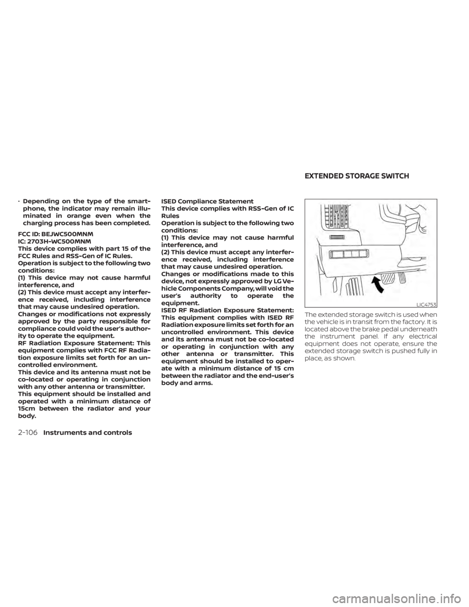
The extended storage switch is used when
the vehicle is in transit from the factory. It is
located above the brake pedal underneath
the instrument panel. If any electrical
equipment does not operate, ensure the
extended storage switch is pushed fully in
place, as shown.
LIC4753
EXTENDED STORAGE SWITCH
2-106Instruments and controls
Page 223 of 665
ROOF RACK (if so equipped)
WARNING
• Always install the crossbars onto the
roof side rails before loading cargo of
any kind. Loading cargo directly onto
the roof side rails or the vehicle’s roof
may cause vehicle damage.
• Roof rack cross bars should be evenly
distributed.
• Do not exceed maximum roof rack
crossbars load capacity and always
distribute the load uniformly. •
Heavy loading of the crossbars has
the potential to affect the vehicle
stability and handling during sudden
or unusual handling maneuvers.
• Properly secure all cargo with ropes
or straps to help prevent it from slid-
ing or shif ting. In a sudden stop or
collision, unsecured cargo could
cause personal injury.
• Drive extra carefully when the vehicle
is loaded at or near the cargo carry-
ing capacity, especially if the signifi-
cant portion of that load is carried on
the crossbars.CAUTION
• Use care when placing or removing
items from the roof rack. If you can-
not comfortably lif t the items onto
the roof rack from the ground, use a
ladder or a stool.
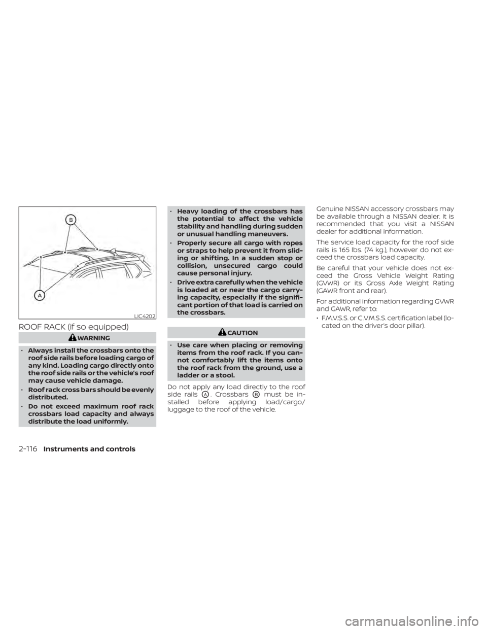
Do not apply any load directly to the roof
side rails
OA. CrossbarsOBmust be in-
stalled before applying load/cargo/
luggage to the roof of the vehicle. Genuine NISSAN accessory crossbars may
be available through a NISSAN dealer. It is
recommended that you visit a NISSAN
dealer for additional information.
The service load capacity for the roof side
rails is 165 lbs. (74 kg.), however do not ex-
ceed the crossbars load capacity.
Be careful that your vehicle does not ex-
ceed the Gross Vehicle Weight Rating
(GVWR) or its Gross Axle Weight Rating
(GAWR front and rear).
For additional information regarding GVWR
and GAWR, refer to:
• F.M.V.S.S. or C.V.M.S.S. certification label (lo-
cated on the driver’s door pillar).
LIC4202
2-116Instruments and controls
Page 225 of 665
To open a window, push the switch to the
detent and continue to hold down until the
desired window position is reached. To
close a window, pull the switch to the de-
tent and continue to hold up until the de-
sired window position is reached.
Locking rear passengers'
windows
When the window lock button is pushed
(the indicator illuminates), the rear passen-
gers’ windows cannot be operated with the
rear passengers’ power window switch.
The rear passengers’ windows can only be
operated with the main switch (driver side
switches). To cancel the passenger’s win-
dow lock, push the window lock button
again.
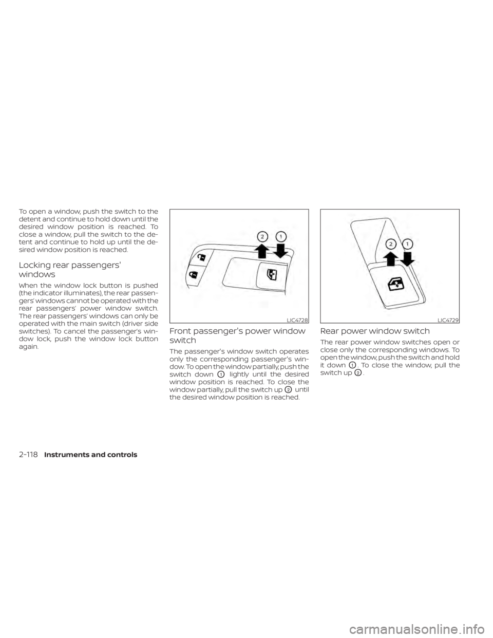
Front passenger's power window
switch
The passenger's window switch operates
only the corresponding passenger's win-
dow. To open the window partially, push the
switch down
O1lightly until the desired
window position is reached. To close the
window partially, pull the switch up
O2until
the desired window position is reached.
Rear power window switch
The rear power window switches open or
close only the corresponding windows. To
open the window, push the switch and hold
it down
O1. To close the window, pull the
switch up
O2.
LIC4728LIC4729
2-118Instruments and controls
Page 229 of 665
If the moonroof switch does not
operate
If the moonroof and sunshade do not op-
erate properly, perform the following pro-
cedure to initialize the operation system.
1. If the moonroof and sunshade are open,close them fully by repeatedly pushing
the moonroof switch to the CLOSE
O2
andO4position.
2. Push and hold the moonroof switch to the CLOSE
O4position for 10 seconds.
3. Af ter the moonroof and sunshade move slightly to the closed position and
then move back a little, release the
moonroof switch.
4. Push and hold the moonroof switch to the CLOSE
O4position, and the glass
and shade will move.
5. Release the moonroof switch. Then the moonroof and sunshade will fully open
and then fully close.
6. Check if the moonroof switch operates normally.
WARNING
The driver is always responsible for op-
erating the moonroof properly, includ-
ing the operation by all passengers.
Failure to follow the warnings and in-
structions for proper use of the moon-
roof could result in serious injury or
death.
• Do not allow children to operate the
moonroof. Improper operation by
children may cause an accident. If
children or others get caught in the
moonroof, it could cause serious
injury.
• To help avoid risk of injury or death
through unintended operation of the
moonroof, place the ignition switch
in the OFF position when leaving the
vehicle, and do not leave children and
the Intelligent Key inside the vehicle.
• Do not activate the auto-reverse
function intentionally. If hands or
face, etc. get caught in the moonroof,
it could cause serious injury.CAUTION
• Do not place objects (such as news-
papers, handkerchiefs, etc.) on the
sunshade when it is extending or re-
tracting causing improper operation
or damage to the sunshade.
• Do not push the sunshade arm with
your hands, etc., as this may deform
it. Improper operation or damage to
the sunshade may result.
• Do not put any object into the sun-
shade inlet port as this may result in
improper operation or damage the
sunshade.
• Do not hang any object on the arm
rail as this may result in improper op-
eration or damage the sunshade.
• Do not forcefully pull the sunshade.
Doing so may elongate the sun-
shade. Improper operation or dam-
age to the sunshade may result.
If the moonroof does not operate properly
af ter performing the procedure above,
have your vehicle checked by a NISSAN
dealer.
2-122Instruments and controls
Page 236 of 665
CLEARING THE PROGRAMMED
INFORMATION
The following procedure clears the pro-
grammed information from three buttons.
Individual buttons cannot be cleared. How-
ever, individual buttons can be repro-
grammed. For additional information, see
“Reprogramming a single HomeLink® but-
ton” (P. 2-129).
To clear all programming
1. Press and hold the two outer HomeLink®buttons until the indicator light begins to
flash in green in approximately 10 sec-
onds. Do not hold for longer than 20
seconds.
2. Release both buttons.
HomeLink® is now in the programming
mode and can be programmed at any
time beginning with “Programming
HomeLink®” - Step 1.
REPROGRAMMING A SINGLE
HOMELINK® BUTTON
To reprogram a HomeLink® button, com-
plete the following:
1. Press and hold the desired HomeLink® button. DO NOT release the button. 2. The indicator light will illuminate in
green, and af ter 20 seconds it will begin
to flash in orange.
3. Release the HomeLink® button and pro- ceed with “ Programming HomeLink®” —
Step 3.
For questions or comments, contact
HomeLink® at: www.homelink.com/nissan
or 1–800–355–3515.
The HomeLink® button has now been re-
programmed. The new device can be acti-
vated by pressing the HomeLink® button
that was just programmed. This procedure
will not affect any other programmed
HomeLink® buttons.
If a new device is not programmed to the
HomeLink® button, it will revert to the pre-
viously stored programming.
IF YOUR VEHICLE IS STOLEN
If your vehicle is stolen, you should change
the codes of any non-rolling code device
that has been programmed into HomeLink®.
Consult the Owner's Manual of each device
or call the manufacturer or dealer of those
devices for additional information.
When your vehicle is recovered, you will
need to reprogram the HomeLink® Uni- versal Transceiver with your new trans-
mitter information.
FCC Notice:
For USA:
This device complies with Part 15 of the
FCC Rules. Operation is subject to the fol-
lowing two conditions: (1) This device
may not cause harmful interference, and
(2) this device must accept any interfer-
ence received, including interference
that may cause undesired operation.
NOTE:
Changes or modifications not expressly
approved by the party responsible for
compliance could void the user’s author-
ity to operate the equipment.
For Canada:
This device contains licence-exempt
transmitter(s)/receiver(s) that comply
with Innovation, Science and Economic
Development Canada’s licence-exempt
RSS(s). Operation is subject to the fol-
lowing two conditions: (1) This device
may not cause interference. (2) This de-
vice must accept any interference, in-
cluding interference that may cause un-
desired operation of the device.
Instruments and controls2-129
Page 242 of 665
When the doors are locked using one of the
following methods, the doors cannot be
opened using the inside or outside door
handles. The doors must be unlocked to
open the doors.
WARNING
• Always have the doors locked while
driving. Along with the use of seat
belts, this provides greater safety in
the event of an accident by helping to
prevent persons from being thrown
from the vehicle. This also helps keep
children and others from uninten-
tionally opening the doors, and will
help keep out intruders.
• Before opening any door, always look
for and avoid oncoming traffic. •
To help avoid risk of injury or death
through unintended operation of the
vehicle and/or its systems, including
entrapment in windows or inadver-
tent door lock activation, do not
leave children, people who require
the assistance of others or pets unat-
tended in your vehicle. Additionally,
the temperature inside a closed ve-
hicle on a warm day can quickly be-
come high enough to cause a signifi-
cant risk of injury or death to people
and pets.
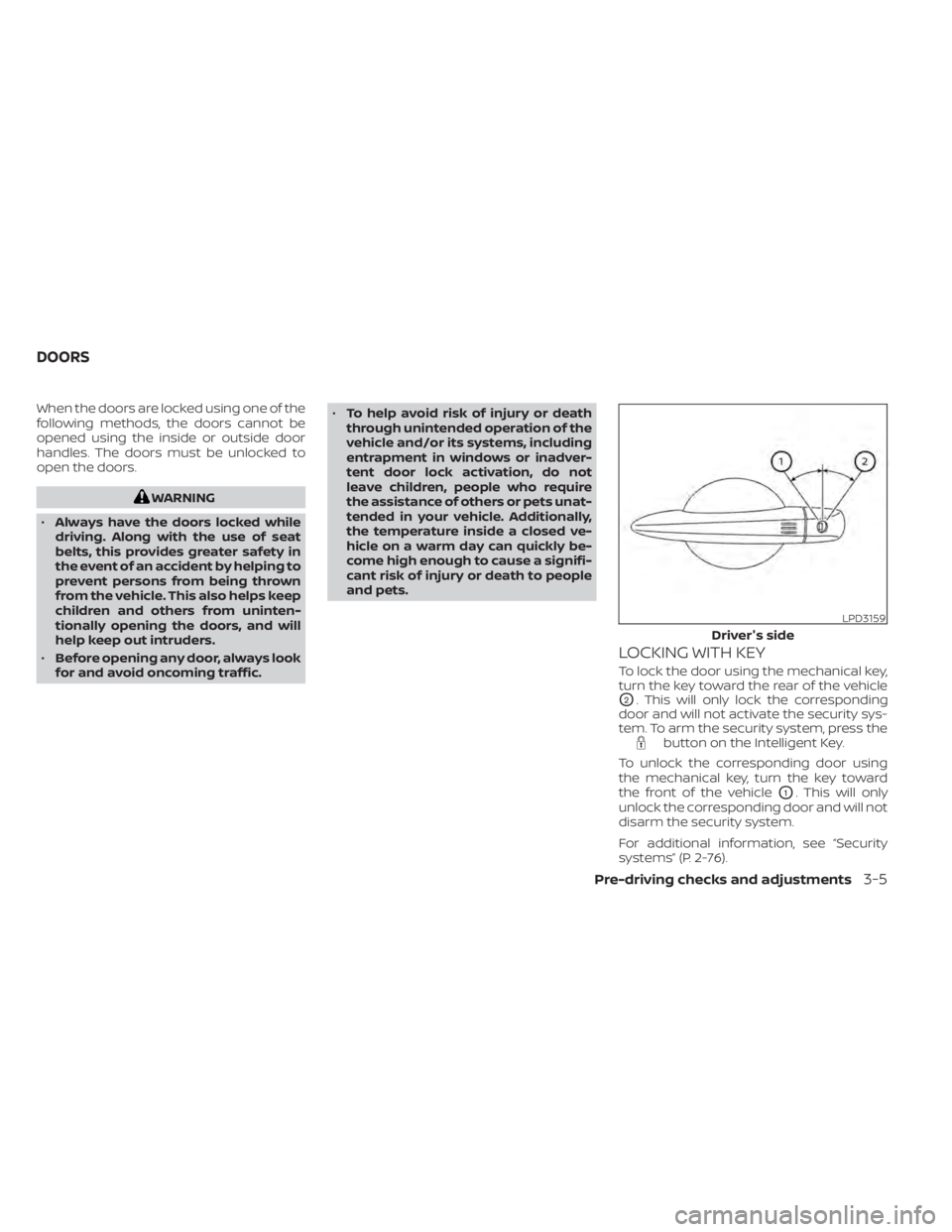
LOCKING WITH KEY
To lock the door using the mechanical key,
turn the key toward the rear of the vehicle
O2. This will only lock the corresponding
door and will not activate the security sys-
tem. To arm the security system, press the
button on the Intelligent Key.
To unlock the corresponding door using
the mechanical key, turn the key toward
the front of the vehicle
O1. This will only
unlock the corresponding door and will not
disarm the security system.
For additional information, see “Security
systems” (P. 2-76).
LPD3159
Driver's side
DOORS
Pre-driving checks and adjustments3-5