2023 HYUNDAI IONIQ 5 ECU
[x] Cancel search: ECUPage 600 of 680

Emergency Situations
8-22
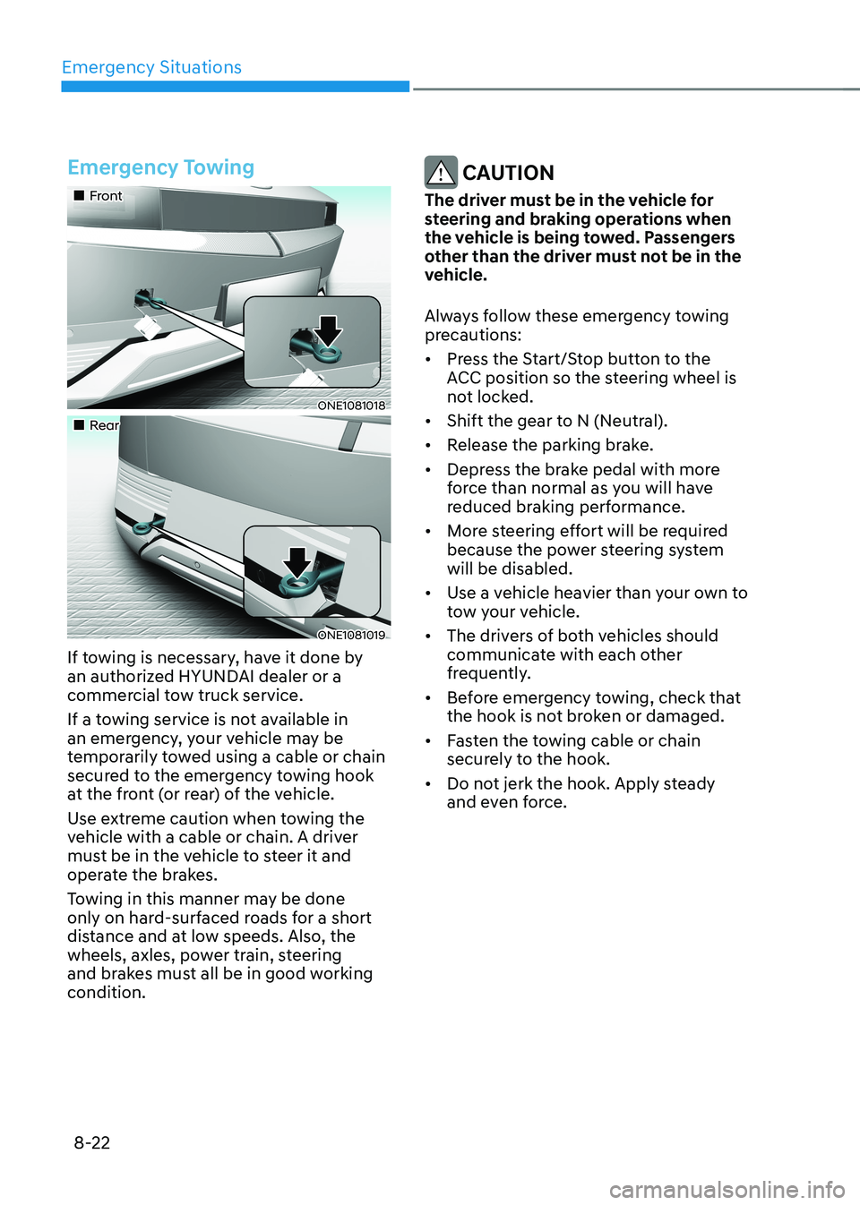
Emergency Towing
„„Front
ONE1081018
„„Rear
ONE1081019
If towing is necessary, have it done by
an authorized HYUNDAI dealer or a
commercial tow truck service.
If a towing service is not available in
an emergency, your vehicle may be
temporarily towed using a cable or chain
secured to the emergency towing hook
at the front (or rear) of the vehicle.
Use extreme caution when towing the
vehicle with a cable or chain. A driver
must be in the vehicle to steer it and
operate the brakes.
Towing in this manner may be done
only on hard-surfaced roads for a short
distance and at low speeds. Also, the
wheels, axles, power train, steering
and brakes must all be in good working condition.
CAUTION
The driver must be in the vehicle for
steering and braking operations when
the vehicle is being towed. Passengers
other than the driver must not be in the
vehicle.
Always follow these emergency towing
precautions: • Press the Start/Stop button to the
ACC position so the steering wheel is
not locked.
• Shift the gear to N (Neutral).
• Release the parking brake.
• Depress the brake pedal with more
force than normal as you will have
reduced braking performance.
• More steering effort will be required
because the power steering system will be disabled.
• Use a vehicle heavier than your own to
tow your vehicle.
• The drivers of both vehicles should
communicate with each other
frequently.
• Before emergency towing, check that
the hook is not broken or damaged.
• Fasten the towing cable or chain
securely to the hook.
• Do not jerk the hook. Apply steady
and even force.
Page 621 of 680

Maintenance
9-20
For best battery service
ONE1091009
• Keep the battery securely mounted.
• Keep the battery top clean and dry.
• Keep the terminals and connections
clean, tight, and coated with
petroleum jelly or terminal grease.
• Rinse any spilled electrolyte from the
battery immediately with a solution of
water and baking soda.
• If the vehicle is not going to be used
for an extended time, disconnect the
battery cables.
Battery Capacity Label
OLMB073072
à The actual battery label in the vehicle
may differ from the illustration.
1. CMF60L-BCI : The HYUNDAI model name of battery
2. 12V : The nominal voltage
3. 60Ah(20HR) : The nominal capacity (in Ampere hours)
4. 92RC : The nominal reserve capacity
(in min.)
5. 550CCA : The cold-test current in amperes by SAE
6. 440A : The cold-test current in amperes by EN
Battery Recharging
By battery charger
Your vehicle has a maintenance-free,
calcium-based battery. • If the battery becomes discharged
over a short time (because, for
example, the headlamps or interior
lights were left on while the vehicle
was not in use), recharge it by slow
charging (trickle) for 10 hours.
• If the battery gradually discharges
because of high electrical load while
the vehicle is being used, recharge it
at 20-30A for two hours.
Page 638 of 680

09
9-37
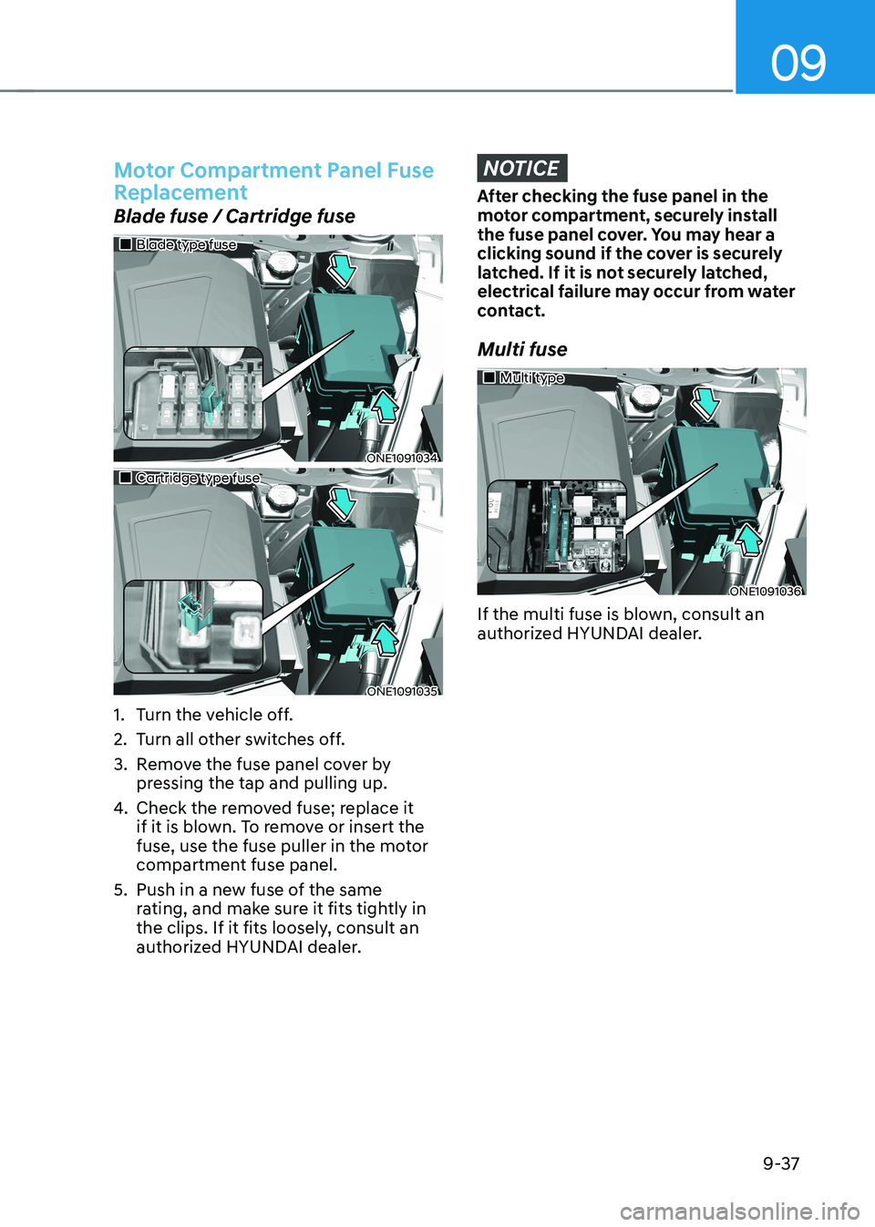
Motor Compartment Panel Fuse
Replacement
Blade fuse / Cartridge fuse
„„Blade type fuse
ONE1091034
„„Cartridge type fuse
ONE1091035
1. Turn the vehicle off.
2. Turn all other switches off.
3. Remove the fuse panel cover by pressing the tap and pulling up.
4. Check the removed fuse; replace it
if it is blown. To remove or insert the
fuse, use the fuse puller in the motor
compartment fuse panel.
5. Push in a new fuse of the same rating, and make sure it fits tightly in
the clips. If it fits loosely, consult an
authorized HYUNDAI dealer.
NOTICE
After checking the fuse panel in the
motor compartment, securely install
the fuse panel cover. You may hear a
clicking sound if the cover is securely
latched. If it is not securely latched,
electrical failure may occur from water
contact.
Multi fuse
„„Multi type
ONE1091036
If the multi fuse is blown, consult an
authorized HYUNDAI dealer.
Page 641 of 680

Maintenance
9-40
Instrument panel fuse panel
Fuse NameFuse Rating Circuit Protected
FRT SEAT HEATER 20AFront Air Ventilation Seat Control Module, Front Seat
Warmer Control Module
WASHER 15A Multifunction Switch
IBU2 7.5A IBU
IG3 9 10A
SCU, Rear Inverter, BMU
BMS 10A
BMU
A/BAG2 10A
SRS Control Module
WIN LH 25ADriver Safety Power Window Module, Passenger
Safety Power, Rear Power Window Switch LH
SPARE1 15A Not Used
E-SHIFTER3 10A
Electronic ATM Shift Lever
MODULE4 10AFront/Rear Corner Radar LH/RH, Front/Rear Inverter,
Crash Pad Switch, ADAS Driving ECU, VESS Unit,
Front Radar, Front View Camera, ADAS Parking ECU
USB CHARGER 15A Front USB Charger #1, Front USB Charger #2
Page 673 of 680

Index
I-8
Instrument cluster .................................................................................................. 4-4
Gauges and Meters ............................................................................................. 4-5
Instrument Cluster Control ................................................................................. 4-5
LCD Display Messages .................................................................................... 4-19
Power/Charge Gauge .......................................................................................... 4-6
Reduction Gear Shift Indicator .......................................................................... 4-9
State of Charge (SOC) Gauge for High Voltage Battery ....................................4-6
Warning and Indicator Lights ............................................................................. 4-9
Instrument Panel Overview (I) .............................................................................. 2-5
Instrument Panel Overview (II) ............................................................................. 2-6
Integrated Memory System.................................................................................. 5-40
Recalling Memory Positions ............................................................................ 5-40
Resetting the System ........................................................................................ 5-41
Seat Easy Access .............................................................................................. 5-42
Storing Memory Positions ................................................................................ 5-40
Intelligent Speed Limit Assist (ISLA) ................................................................. 7-56
Intelligent Speed Limit Assist Malfunction and Limitations ...........................7-59
Intelligent Speed Limit Assist Operation .........................................................7-57
Intelligent Speed Limit Assist Settings ............................................................7-56
Interior Features ................................................................................................. 5-121
Cargo Security Screen .................................................................................... 5-130
Clock .............................................................................................................. 5-127
Cluster Fascia Side Panel ............................................................................... 5-127
Coat Hook ...................................................................................................... 5-128
Cup Holder ..................................................................................................... 5-121
Floor Mat Anchor(s) ....................................................................................... 5-128
Luggage Net Holder ....................................................................................... 5-129
Power Outlet ................................................................................................... 5-122
Rear Side Window Sunshades ........................................................................ 5-129
Sunvisor .......................................................................................................... 5-122
USB Charger .................................................................................................. 5-123
Vehicle to Load (V2L) ................................................................................... 5-127
Wireless Smart Phone Charging System ........................................................5-124
Interior Overview .................................................................................................. 2-4 J
Jump Starting (12V battery) .................................................................................. 8-4
Page 677 of 680

Index
I-12Seats
....................................................................................................................... 3-3
Advanced Rear Occupant Alert (ROA) ............................................................3-28
Air Ventilation Seats ......................................................................................... 3-26
Front Seats .......................................................................................................... 3-7
Head Restraint .................................................................................................. 3-20
Rear Seats ......................................................................................................... 3-16
Safety Precautions .............................................................................................. 3-6
Seat Warmers .................................................................................................... 3-24
Smart Cruise Control (SCC) ............................................................................... 7-70
Smart Cruise Control Malfunction and Limitations .........................................7-82
Smart Cruise Control Operation ....................................................................... 7-75
Smart Cruise Control Settings .......................................................................... 7-71
Smart Recuperation System ................................................................................. 6-19
How to Operate ................................................................................................ 6-21
Limitations of the System ................................................................................ 6-23
Ready to Operate .............................................................................................. 6-20
Smart Recuperation System Setting ................................................................. 6-19
Smart Recuperation System Will Be Temporarily Cancelled When: ...............6-21
System Malfunction ......................................................................................... 6-23
To Activate Smart Recuperation System ..........................................................6-19
To Resume Smart Recuperation System ..........................................................6-21
Vehicle-to-Vehicle Distance Recognition Sensor (Front Radar) ......................6-22
Special Driving Conditions ................................................................................. 6-53
Driving at Night ............................................................................................... 6-54
Driving in Flooded Areas ................................................................................. 6-55
Driving in the Rain ........................................................................................... 6-54
Hazardous Driving Conditions ......................................................................... 6-53
Highway Driving .............................................................................................. 6-55
Reducing the Risk of a Rollover ...................................................................... 6-56
Rocking the Vehicle .......................................................................................... 6-53
Smooth Cornering ............................................................................................ 6-54