2022 TOYOTA YARIS CROSS ECU
[x] Cancel search: ECUPage 401 of 618

399
7
CV Owner's Manual_Europe_M52N20_en
7-2. Steps to take in an emergency
When trouble arises
temporarily towed using cables or
chains secured to the emergency
towing eyelets. This should only be
attempted on hard surfaced roads
for at most 80 km (50 miles) at
under 30 km/h (18 mph).
A driver must be in the vehicle to
steer and operate the brakes. The
vehicle’s wheels, drivetrain, axles,
steering and brakes must be in
good condition.
For vehicles with a Multidrive, only
the front towing eyelets may be
used.
To have your vehicle towed by
another vehicle, the towing eyelet
must be installed to your vehicle.
Install the towing eyelet using the
following procedure.
1 Take out the wheel nut wrench
and towing eyelet. ( P.417,
427)
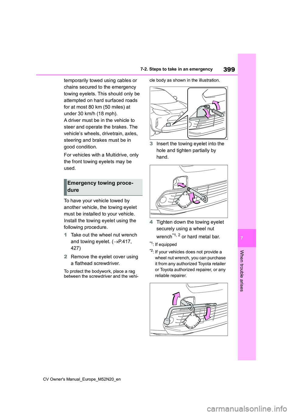
2 Remove the eyelet cover using
a flathead screwdriver.
To protect the bodywork, place a rag between the screwdriver and the vehi-
cle body as shown in the illustration.
3 Insert the towing eyelet into the
hole and tighten partially by
hand.
4 Tighten down the towing eyelet
securely using a wheel nut
wrench*1, 2 or hard metal bar.
*1: If equipped
*2: If your vehicles does not provide a
wheel nut wrench, you can purchase
it from any authorized Toyota retailer
or Toyota authorized repairer, or any
reliable repairer.
Emergency towing proce-
dure
Page 402 of 618

400
CV Owner's Manual_Europe_M52N20_en
7-2. Steps to take in an emergency
5Securely attach cables or chains
to the towing eyelet.
Take care not to damage the vehicle
body.
6 Enter the vehicle being towed
and start the engine.
If the engine does not start, turn the
engine switch to ON.
7 Shift the shift lever to N and
release the parking brake.
Turn automatic mode off.
( P.187)
Multidrive: When the shift lever
cannot be shifted: P. 1 8 0
■While towing
If the engine is not running, the power assist for the brakes and steering will
not function, making steering and brak- ing more difficult.
■Wheel nut wrench*1, 2
Wheel nut wrench is installed in luggage compartment. ( P.427)*1: If equipped
*2: If your vehicles does not provide a
wheel nut wrench, you can purchase
it from any authorized Toyota retailer
or Toyota authorized repairer, or any
reliable repairer.
WARNING
Observe the following precautions. Failure to do so may result in death or serious injury.
■While towing
●When towing using cables or chains, avoid sudden starts, etc.
which place excessive stress on the towing eyelets, cables or chains. The towing eyelets, cables or
chains may become damaged, bro- ken debris may hit people, and cause serious damage.
●Do not turn the engine switch off.There is a possibility that the steer-
ing wheel is locked and cannot be operated.
■Installing towing eyelets to the vehicle
Make sure that towing eyelets are
installed securely. If not securely installed, towing eye-lets may come loose during towing.
■To prevent damage to the vehicle during emergency towing
Do not secure cables or chains to the suspension components.
Page 426 of 618

424
CV Owner's Manual_Europe_M52N20_en
7-2. Steps to take in an emergency
replaced, make sure to tell any autho-
rized Toyota retailer or Toyota autho- rized repairer, or any reliable repairer that the sealant is injected.
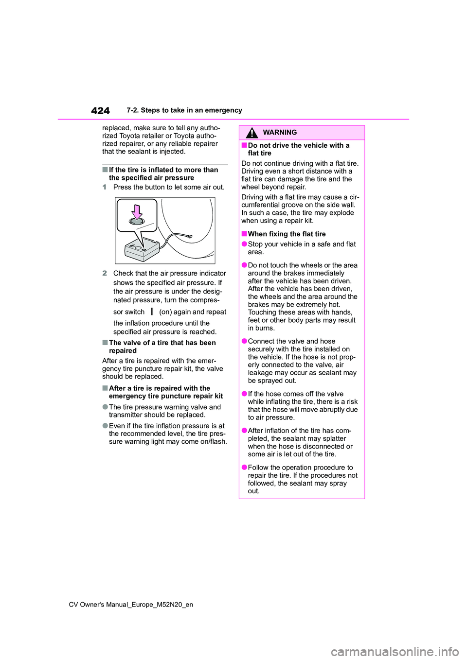
■If the tire is inflated to more than the specified air pressure
1 Press the button to let some air out.
2 Check that the air pressure indicator
shows the specified air pressure. If
the air pressure is under the desig-
nated pressure, turn the compres-
sor switch (on) again and repeat
the inflation procedure until the
specified air pressure is reached.
■The valve of a tire that has been repaired
After a tire is repaired with the emer-
gency tire puncture repair kit, the valve should be replaced.
■After a tire is repaired with the emergency tire puncture repair kit
●The tire pressure warning valve and transmitter should be replaced.
●Even if the tire inflation pressure is at the recommended level, the tire pres-
sure warning light may come on/flash.
WARNING
■Do not drive the vehicle with a flat tire
Do not continue driving with a flat tire. Driving even a short distance with a flat tire can damage the tire and the
wheel beyond repair.
Driving with a flat tire may cause a cir- cumferential groove on the side wall.
In such a case, the tire may explode when using a repair kit.
■When fixing the flat tire
●Stop your vehicle in a safe and flat area.
●Do not touch the wheels or the area around the brakes immediately
after the vehicle has been driven. After the vehicle has been driven, the wheels and the area around the
brakes may be extremely hot. Touching these areas with hands, feet or other body parts may result
in burns.
●Connect the valve and hose
securely with the tire installed on the vehicle. If the hose is not prop-erly connected to the valve, air
leakage may occur as sealant may be sprayed out.
●If the hose comes off the valve while inflating the tire, there is a risk that the hose will move abruptly due
to air pressure.
●After inflation of the tire has com-
pleted, the sealant may splatter when the hose is disconnected or some air is let out of the tire.
●Follow the operation procedure to repair the tire. If the procedures not
followed, the sealant may spray out.
Page 431 of 618

429
7
CV Owner's Manual_Europe_M52N20_en
7-2. Steps to take in an emergency
When trouble arises
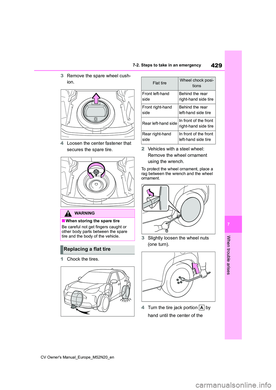
3Remove the spare wheel cush-
ion.
4 Loosen the center fastener that
secures the spare tire.
1 Chock the tires.
2 Vehicles with a steel wheel:
Remove the wheel ornament
using the wrench.
To protect the wheel ornament, place a
rag between the wrench and the wheel ornament.
3 Slightly loosen the wheel nuts
(one turn).
4 Turn the tire jack portion by
hand until the center of the
WARNING
■When storing the spare tire
Be careful not get fingers caught or other body parts between the spare
tire and the body of the vehicle.
Replacing a flat tire
Flat tireWheel chock posi-
tions
Front left-hand
side
Behind the rear
right-hand side tire
Front right-hand
side
Behind the rear
left-hand side tire
Rear left-hand sideIn front of the front
right-hand side tire
Rear right-hand
side
In front of the front
left-hand side tire
Page 436 of 618

434
CV Owner's Manual_Europe_M52N20_en
7-2. Steps to take in an emergency
WARNING
• PCS (Pre-Collision System) (if equipped)
• LTA (Lane Tracing Assist) (if equipped)
• Tire pressure warning system
• Toyota parking assist-sensor (if equipped)
• PKSB (Parking Support Brake) (if equipped)
• BSM (Blind Spot Monitor) (if equipped)
• Rear view monitor system (if equipped)
• Navigation system (if equipped)
■Speed limit when using the com-
pact spare tire (if equipped)
Do not drive at speeds in excess of 80 km/h (50 mph) when a compact spare
tire is installed on the vehicle.
The compact spare tire is not
designed for driving at high speeds. Failure to observe this precaution may lead to an accident causing
death or serious injury.
■After using the tools and jack
Before driving, make sure all the tools and jack are securely in place in their storage location to reduce the possi-
bility of personal injury during a colli- sion or sudden braking.
NOTICE
■Be careful when driving over bumps with the compact spare
tire (if equipped) installed on the vehicle.
The vehicle becomes lower when
driving with the compact spare tire compared to when driving with stan-dard tires. Be careful when driving
over uneven road surfaces.
■Driving with tire chains and the
compact spare tire (if equipped)
Do not fit tire chains to the compact spare tire. Tire chains may damage
the vehicle body and adversely affect driving performance.
■When replacing the tires
When removing or fitting the wheels, tires or the tire pressure warning
valve and transmitter, contact any authorized Toyota retailer or Toyota authorized repairer, or any reliable
repairer as the tire pressure warning valve and transmitter may be dam-aged if not handled correctly.
■To avoid damage to the tire pres-sure warning valves and trans-
mitters (except for compact spare)
When a tire is repaired with liquid
sealants, the tire pressure warning valve and transmitter may not operate properly. If a liquid sealant is used,
contact any authorized Toyota retailer or Toyota authorized repairer, or any reliable repairer as soon as possible.
Make sure to replace the tire pressure warning valve and transmitter when replacing the tire. ( P.366)
Page 442 of 618

440
CV Owner's Manual_Europe_M52N20_en
7-2. Steps to take in an emergency
Positive (+) battery terminal (your vehicle)
Positive (+) battery terminal (second vehicle)
Negative (-) battery terminal (second vehicle)
Solid, stationary, unpainted metallic point away from the batte ry and any
moving parts as shown in the illustration
4 Start the engine of the second
vehicle. Increase the engine
speed slightly and maintain at
that level for approximately 5
minutes to recharge the battery
of your vehicle.
5 Vehicles with a smart entry &
start system: Open and close
any of the doors of your vehicle
with the engine switch OFF.
6 Maintain the engine speed of
the second vehicle and start the
engine of your vehicle by turning
the engine switch to ON.
7 Once the vehicle’s engine has
started, remove the jumper
cables in the exact reverse
order from which they were con-
nected.
Once the engine starts, have the
vehicle inspected at any autho-
rized Toyota retailer or Toyota
authorized repairer, or any reliable
repairer as soon as possible.
■Starting the engine when the bat- tery is discharged
The engine cannot be started by push-
starting.
■To prevent battery discharge
●Turn off the headlights and the audio
system while the engine is stopped.
●Turn off any unnecessary electrical
components when the vehicle is run- ning at a low speed for an extended
period, such as in heavy traffic.
■When the battery is removed or dis- charged
●Information stored in the ECU is cleared. When the battery is depleted, have the vehicle inspected at any
authorized Toyota retailer or Toyota authorized repairer, or any reliable repairer.
●Some systems may require initializa-tion. ( P.467)
■When removing the battery termi-
nals
When the battery terminals are removed, the information stored in the
ECU is cleared. Before removing the battery terminals, contact any autho-rized Toyota retailer or Toyota autho-
rized repairer, or any reliable repairer.
■Charging the battery
The electricity stored in the battery will discharge gradually even when the vehi-
cle is not in use, due to natural dis- charge and the draining effects of certain electrical appliances. If the vehi-
cle is left for a long time, the battery may discharge, and the engine may be unable to start. (The battery recharges
automatically during driving.)
■When recharging or replacing the battery (vehicles with a smart entry & start system)
●In some cases, it may not be possible to unlock the doors using the smart
Page 443 of 618

441
7
CV Owner's Manual_Europe_M52N20_en
7-2. Steps to take in an emergency
When trouble arises
entry & start system when the battery
is discharged. Use the wireless remote control or the mechanical key to lock or unlock the doors.
●The engine may not start on the first attempt after the battery has
recharged but will start normally after the second attempt. This is not a mal-function.
●The engine switch mode is memo-rized by the vehicle. When the battery
is reconnected, the system will return to the mode it was in before the bat-tery was discharged. Before discon-
necting the battery, turn the engine switch off.If you are unsure what mode the
engine switch was in before the bat- tery discharged, be especially careful when reconnecting the battery.
●The Stop & Start system may not automatically stop the engine for up to
an hour.
■When replacing the battery
●Use a battery that conforms to Euro-
pean regulations.
●Use a battery that the case size is
same as the previous one, 20 hour rate capacity (20HR) is equivalent or greater, and performance rating
(CCA) is equivalent or greater. Check the label on top of the battery for the battery size and specifications (ex.
LN2, 60Ah, 345A). • If the sizes differ, the battery cannot be properly secured.
• If the 20 hour rate capacity is low, even if the time period where the vehi-cle is not used is a short time, the bat-
tery may discharge and the engine may not be able to start.
●For details, consult any authorized Toyota retailer or Toyota authorized repairer, or any reliable repairer.
WARNING
■When removing the battery ter-minals
Always remove the negative (-) termi- nal first. If the positive (+) terminal contacts any metal in the surrounding
area when the positive (+) terminal is removed, a spark may occur, leading to a fire in addition to electrical shocks
and death or serious injury.
■Avoiding battery fires or explo-
sions
Observe the following precautions to prevent accidentally igniting the flam-
mable gas that may be emitted from the battery:
●Make sure each jumper cable is connected to the correct terminal and that it is not unintentionally in
contact with any other than the intended terminal.
●Do not allow the other end of the jumper cable connected to the “+” terminal to come into contact with
any other parts or metal surfaces in the area, such as brackets or unpainted metal.
●Do not allow the + and - clamps of the jumper cables to come into con-
tact with each other.
●Do not smoke, use matches, ciga-
rette lighters or allow open flame near the battery.
■Battery precautions
The battery contains poisonous and corrosive acidic electrolyte, while
related parts contain lead and lead compounds. Observe the following precautions when handling the bat-
tery:
Page 462 of 618

460
CV Owner's Manual_Europe_M52N20_en
8-2. Customization
■Smart entry & start system* and wireless remote control (P.119,
136)
*: If equipped
■Smart entry & start system* ( P.119, 125, 136)
*: If equipped
■Wireless remote control (P.116, 119)
■Power back door* (P.126)
FunctionDefault settingCustomized setting
Operation signal (Emer-
gency flashers)OnOffO—O
Time elapsed before auto-
matic door lock function is
activated if door is not
opened after being
unlocked
30 seconds
60 seconds
——O120 seconds
Open door warning buzzerOnOff——O
FunctionDefault settingCustomized setting
Smart entry & start systemOnOffO—O
Number of consecutive
door lock operations2 timesAs many as desired——O
FunctionDefault settingCustomized setting
Wireless remote controlOnOff——O
FunctionDefault settingCustomized setting
Power back doorOnOff—O—
Power back door opening
position51 to 4—O—
User optional setting—O—
Buzzer volumeLevel 3Level 1—O—Level 2
Kick sensorOnOff—O—