Page 490 of 618

4926-3. Do-it-yourself maintenance
Owners Manual_USA_M0C031_en
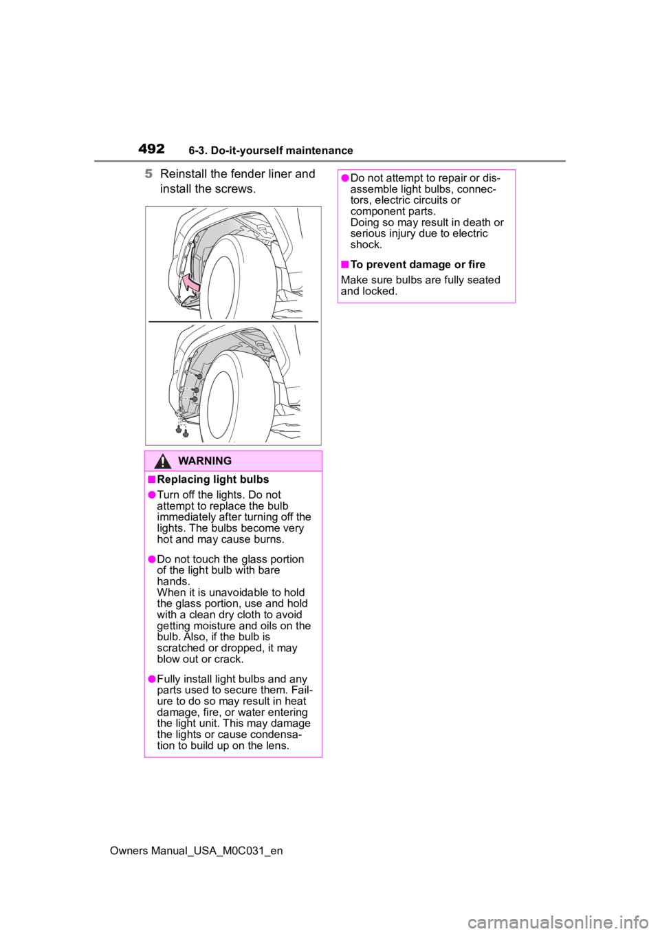
5Reinstall the fender liner and
install the screws.
WARNING
■Replacing light bulbs
●Turn off the lights. Do not
attempt to replace the bulb
immediately after turning off the
lights. The bulbs become very
hot and may cause burns.
●Do not touch the glass portion
of the light bulb with bare
hands.
When it is unavoidable to hold
the glass portion, use and hold
with a clean dry cloth to avoid
getting moisture and oils on the
bulb. Also, if the bulb is
scratched or dropped, it may
blow out or crack.
●Fully install light bulbs and any
parts used to secure them. Fail-
ure to do so may result in heat
damage, fire, or water entering
the light unit. This may damage
the lights or cause condensa-
tion to build up on the lens.
●Do not attempt to repair or dis-
assemble light bulbs, connec-
tors, electric circuits or
component parts.
Doing so may result in death or
serious injury due to electric
shock.
■To prevent damage or fire
Make sure bulbs are fully seated
and locked.
Page 504 of 618

5067-2. Steps to take in an emergency
Owners Manual_USA_M0C031_en
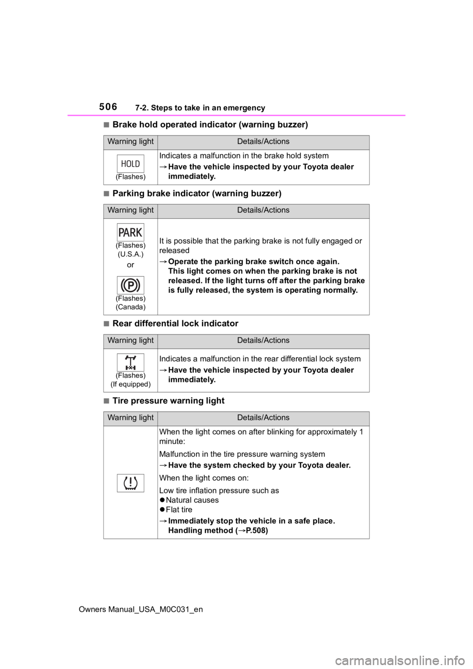
■Brake hold operated indicator (warning buzzer)
■Parking brake indicator (warning buzzer)
■Rear differential lock indicator
■Tire pressure warning light
Warning lightDetails/Actions
(Flashes)
Indicates a malfunction in the brake hold system
Have the vehicle inspecte d by your Toyota dealer
immediately.
Warning lightDetails/Actions
(Flashes)
(U.S.A.)
or
(Flashes)
(Canada)
It is possible that the parking brake is not fully engaged or
released
Operate the parking br ake switch once again.
This light comes on when t he parking brake is not
released. If the lig ht turns off after the parking brake
is fully released, the syst em is operating normally.
Warning lightDetails/Actions
(Flashes)
(If equipped)
Indicates a malfunction in the rear differential lock system
Have the vehicle inspecte d by your Toyota dealer
immediately.
Warning lightDetails/Actions
When the light comes on after b linking for approximately 1
minute:
Malfunction in the tire pressure warning system
Have the system checked by your Toyota dealer.
When the light comes on:
Low tire inflation pressure such as
Natural causes
Flat tire
Immediately stop the v ehicle in a safe place.
Handling method ( P.508)
Page 510 of 618

5127-2. Steps to take in an emergency
Owners Manual_USA_M0C031_entems such as PCS (Pre-Collision
system) or the dynamic radar cruise
control with full-speed range is oper-
ating. If a warning message is
shown, be sure to decelerate the
vehicle or follow an instruction
shown on the multi
-information dis-
play.
A warning message is shown when
Brake Override System operates.
( P.172)
A warning message is shown when
Drive-Start Control ( P.177) or
Parking Support Brake ( P.287)
operates. Follow the instructions on
the multi-information display.
●If a message about an operation
of the power switch is displayed
An instruction for operation of the
power switch is shown when the
incorrect procedure for starting the
hybrid system is performed or the
power switch is operated incorrectly.
Follow the instructions shown on the
multi-information display to operate
the power switch again.
●If a message abou t a shift lever
operation is displayed
To prevent the shift lever from being
operated incorrectly or the vehicle
from moving unexpectedly, a mes-
sage that requires shifting the shift
lever may be sho wn on the multi-
information display . In that case, fol-
low the instruction of the message
and shift the shift lever.
●If a message or image about an
open/close state of a part or
replenishment of a consumable is
displayed
Confirm the part indicated by the
multi-information display or a warn-
ing light, and then perform the cop-
ing method such as closing the open door or replenishing a con-
sumable.
■If a message that indicates the
need for visiting your Toyota
dealer is displayed
The system or part shown on the
multi-information di splay is malfunc-
tioning. Have the vehicle inspected
by your Toyota dealer immediately.
■If a message that indicates the
need for referring to Owner’s
Manual is displayed
●If “Engine Coolant Temp High
Stop in a Safe Place See Owner’s
Manual” is shown, follow the
instructions ( P.535).
●If the following messages are
shown, there may be a malfunc-
tion.
Immediately stop the vehicle in a
safe place and contact your Toy-
ota dealer. Continuing to drive the
vehicle may be dangerous.
• “Hybrid System Malfunction”
• “Check Engine”
• “Traction battery system malfunc- tion”
• “Accelerator System Malfunction”
• “Hybrid System Stopped”
• “Smart Key System Malfunction See Owner’s Manual”
●If the following messages are
shown, there may be a malfunc-
tion.
Immediately have the vehicle
inspected by your Toyota dealer.
• “Oil Pressure Low Stop in a Safe Place See Owner’s Manual”
• “Braking Power Low Stop in a
Safe Place See Owner’s Manual”
●If “Maintenance Required for Trac-
tion Battery Cooling Parts See
Owner’s Manual” is shown, the fil-
ter may be clogged, the air intake
vent may be blocked, or there may
be a gap in the duct. Therefore,
perform the follo wing correction
procedure.
• If the air intake vent or filter of the hybrid battery (traction battery)
are dirty, perform the procedures
Page 513 of 618

5157-2. Steps to take in an emergency
Owners Manual_USA_M0C031_en
7
When trouble arises
Stop the vehicle in a safe
place on a hard, flat surface.
Set the parking brake.
Shift the shift lever to P.
Stop the hybrid system.
Turn on the emergency flash-
ers. ( P.494)
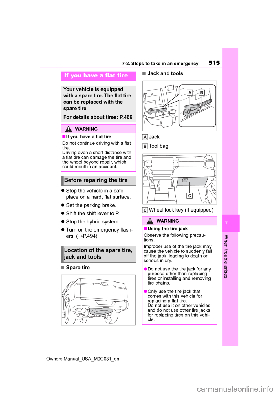
■Spare tire
■Jack and tools
Jack
Tool bag
Wheel lock key (if equipped)If you have a flat tire
Your vehicle is equipped
with a spare tire. The flat tire
can be replaced with the
spare tire.
For details about tires: P.466
WARNING
■If you have a flat tire
Do not continue driving with a flat
tire.
Driving even a short distance with
a flat tire can damage the tire and
the wheel beyond repair, which
could result in an accident.
Before repairing the tire
Location of the spare tire,
jack and tools
WARNING
■Using the tire jack
Observe the following precau-
tions.
Improper use of the tire jack may
cause the vehicle to suddenly fall
off the jack, leading to death or
serious injury.
●Do not use the tire jack for any
purpose other than replacing
tires or installing and removing
tire chains.
●Only use the tire jack that
comes with this vehicle for
replacing a flat tire.
Do not use it on other vehicles,
and do not use other tire jacks
for replacing tires on this vehi-
cle.
Page 514 of 618

5167-2. Steps to take in an emergency
Owners Manual_USA_M0C031_en
When replacing tires on a vehi-
cle with wheel lock nuts, use the
following procedures to remove
and install the wheel lock nuts.
The wheel lock key is stored in
the glove box. Always return the
wheel lock key to its original
position after use, so that it does not get lost. (
P.515)
■Removal
For ease of removal, the wheel
lock nut should always be the
first one loosened.
1 Place the wheel lock key on
top of the wheel lock nut,
turning until the wheel lock
key and wheel lock nut pat-
terns engage.
2 Place the wheel nut wrench
on the wheel lock key, and
while applying pressure on
the wheel lock key, loosen
the wheel lock nut.
■Installation
For ease of installation, the
wheel lock nut should always be
the last one tightened.
1 By hand, install a wheel lock
nut on each wheel.
2 Place the wheel lock key on
top of the wheel lock nut,
turning until the wheel lock
key and wheel lock nut pat-
terns engage.
3 Place the wheel nut wrench
on the wheel lock key, and
while applying pressure on
the wheel lock key, tighten
the wheel lock nut to the rec-
ommended torque.
WARNING
●Put the jack prope rly in its jack
point.
●Do not put any part of your body
under the vehicle while it is sup-
ported by the jack.
●Do not start the hybrid system
or drive the vehicle while the
vehicle is suppor ted by the jack.
●Do not raise the vehicle while
someone is inside.
●When raising the vehicle, do not
put an object on or under the
jack.
●Do not raise the vehicle to a
height greater than that required
to replace the tire.
●Use a jack stand if it is neces-
sary to get under the vehicle.
●When lowering the vehicle,
make sure that there is no-one
near the vehicle. If there are
people nearby, warn them
vocally before lowering.
■Using the jack handle
Insert the square head securely
until you hear a click to prevent
the extension parts from coming
apart unexpectedly.
Wheel lock nut (if
equipped)
Page 515 of 618
5177-2. Steps to take in an emergency
Owners Manual_USA_M0C031_en
7
When trouble arises
1 Fold the head restraint
( P.141), and then pull the
strap and then fold down the
seatback.
2 Loosen and remove the jack.
1 Loosen
2 Tighten
After using the jack, install the jack
in the exact reverse order from
which they were removed.
3Unhook the tightening strap
and take out the tool bag.
1 Assemble the jack handle
extension as shown.
2 Insert the end of the jack
handle extension into the NOTICE
■When using a wheel lock key
(if equipped)
Do not use an impact wrench.
Using an impact wrench may
cause permanent damage to
wheel lock nut and wheel lock
key. If in doubt about wheel lock
application, contact your Toyota
dealer.
Taking out the jack and
tool bag
Taking out the spare tire
Page 516 of 618
5187-2. Steps to take in an emergency
Owners Manual_USA_M0C031_en
lowering screw and turn it
counterclockwise.
3 After the tire is lowered com-
pletely to the ground, remove
the holding bracket. 1
Chock the tires.
2 Slightly loosen the wheel
nuts (one turn).
Vehicles with wheel locks: Use the
wheel lock key to loosen the wheel
lock.
Replacing a flat tire
TireWheel chock
positions
Front left-hand
sideBehind the rear
right-hand side
tire
Front right-hand
sideBehind the rear
left-hand side tire
Rear left-hand
sideIn front of the
front right-hand
side tire
Rear right-hand
sideIn front of the
front left-hand
side tire
Page 519 of 618
5217-2. Steps to take in an emergency
Owners Manual_USA_M0C031_en
7
When trouble arises
disc wheel seat .
3 Lower the vehicle.
4 Firmly tighten each wheel nut
two or three times in the
order shown in the illustra-
tion.
Vehicles with wheel locks:
Tighten the wheel lock using the
wheel lock key after tightening the
other wheel nuts.
Tightening torque:
154 ft•lbf (209 N•m, 21.3 kgf•m)
1Remove the center wheel
ornament by pushing from
the reverse side.
2 Lay down the tire with the
valve stem facing up and
install the holding bracket.
Turn the jack handle exten-
sion clockwise to take up
slack in the chain.
3 Check to ensure the holding
bracket is centered in the
wheel hub.
WARNING
■Stowing the flat tire
Failure to follow steps listed under
stowing the tire may result in
damage to the spare tire carrier
and loss of the tire, which could
result in serious injury or death.
Stowing the flat tire, jack
and all tools