2022 TOYOTA SUPRA tire pressure
[x] Cancel search: tire pressurePage 295 of 498
293
5
5-1. MOBILITY
MOBILITY
ized Toyota reta iler or Toyota
authorized repairer, or any reliable
repairer.
The tyre inflation pressure appropri-
ate for the respective load condi-
tions should be used. For example,
if the vehicle is partially loaded, use
the tyre inflation pressure specified
for a partially loaded vehicle.
The current tire pr essure of each
installed wheel can be displayed on
the control display.
To ensure that they are displayed
correctly, the tyre sizes must be
stored in the system and must have
been set, see page 304, for the
mounted tyres.
The current tyre inflation pressure
value is shown on each tyre.
Tyres heat up while driving. The
tyre inflation pressure increases
with the temperature of the tyre.
Tyres have a natural, uniform loss
of tyre inflation pressure.
Inflating devices can display a pres-
sure that may be up to 0.1 bar too
low.
The tyre inflation pressure inscrip-
tions on the tyre inflation pressure
sign on the door pillar only relate to
cold tyres or tyres at the same tem-
perature as the ambient tempera-
ture.
Only check the tyre inflation pres-
sures when the tyres are cold, i.e.:
• If the vehicle has been driven a
distance of no more than 2 km,
1.25 miles.
• If the vehicle has not moved
again for at least 2 hours after a
journey.
Regularly check the tyre inflation
pressure of the emergency wheel in
the boot and correct the pressure if
necessary.
1 Determine the specified tyre
inflation pressures for the tyres
installed on the vehicle.
For Australia/New Zealand
WA R N I N G
The inflation pressures on the tyre
label are applicable only for tyres
explicitly mentioned on the label. Inflation pressures for tyres that may
be covered by the label – by size,
speed category and load rating/load index – but not explicitly mentioned
on the label may be different. Please
obtain adequate inflation pressures in accordance with the tyre manufac-
turer's specifications from your tyre
dealer.
On the Control Display
Checking the tyre inflation
pressure
General
Checking using tyre inflation pres-
sure inscriptions on the door pillar
Page 306 of 498

3045-1. MOBILITY
3Insert the plug into the socket in
the vehicle interior.
4 Correct tyre inflation pressure to
at least 2.0 bar.
• To increase tyre inflation pres-
sure: switch on the compressor
with standby state switched on or
the engine running.
• To reduce tyre inflation pressure:
press the button on the compres-
sor.
5 Unscrew the connecting hose of
the compressor from the tyre
valve.
6 Unplug the connector from the
socket in the vehicle interior.
7 Store Mobility System in the
vehicle.
Do not exceed maximum permitted
speed of 80 km/h, approximately 50
mph.
Reset the Tyre Pressure Monitor
(TPM), see page 304.
Have the punctured tyre and the
sealant containe r of the Mobility
System replaced as soon as possi-
ble.
Tire chains cannot be mounted.
Snow tires should be used instead.
The system monitors the tyre infla-
tion pressure in the four fitted tyres.
The system warns if the tyre infla-
tion pressure in one or more tyres
has fallen.
Sensors in the tyre valves measure
the tyre inflation pressure and tyre
temperature.
The system detects the fitted tyres
automatically. The system shows
the preset specified pressures on
the Control Display and compares
them to the current tyre inflation
pressures.
If tyres are fitted which are not
listed on the tyre inflation pressure
labels in the vehicle, see page 292,
Resuming with journey
Snow chains
Selecting tire chains
NOTICE
■Driving with tire chains
Do not fit tire chains. Tire chains may
damage the vehicle body and sus- pension, and adversely affect driving
performance.
Tyre Pressure Monitor (TPM)
Principle
General
Page 310 of 498
3085-1. MOBILITY
sure appears.
■Message
A symbol with a vehicle message is
shown on the Control Display.
■Measure
Check the tyre inflation pressure
and adjust as necessary.
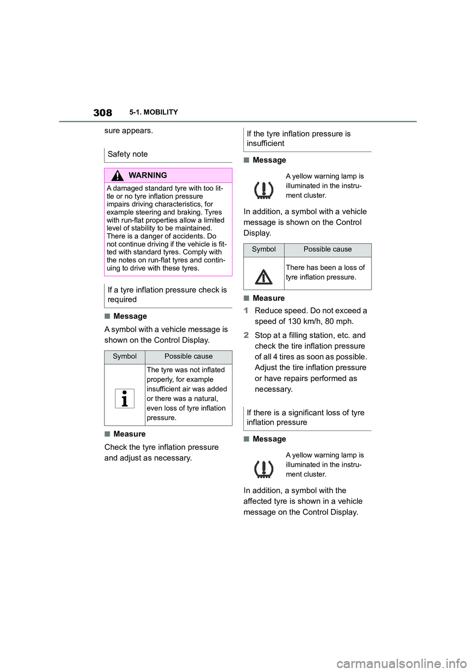
■Message
In addition, a symbol with a vehicle
message is shown on the Control
Display.
■Measure
1 Reduce speed. Do not exceed a
speed of 130 km/h, 80 mph.
2 Stop at a filling station, etc. and
check the tire in flation pressure
of all 4 tires as soon as possible.
Adjust the tire inflation pressure
or have repairs performed as
necessary.
■Message
In addition, a symbol with the
affected tyre is shown in a vehicle
message on the Control Display.
Safety note
WA R N I N G
A damaged standard tyre with too lit-
tle or no tyre inflation pressure impairs driving characteristics, for
example steering and braking. Tyres
with run-flat properties allow a limited
level of stability to be maintained. There is a danger of accidents. Do
not continue driving if the vehicle is fit-
ted with standard tyres. Comply with the notes on run-flat tyres and contin-
uing to drive with these tyres.
If a tyre inflation pressure check is
required
SymbolPossible cause
The tyre was not inflated
properly, for example
insufficient air was added
or there was a natural,
even loss of tyre inflation
pressure.
If the tyre inflation pressure is
insufficient
A yellow warning lamp is
illuminated in the instru-
ment cluster.
SymbolPossible cause
There has been a loss of
tyre inflation pressure.
If there is a significant loss of tyre
inflation pressure
A yellow warning lamp is
illuminated in the instru-
ment cluster.
Page 319 of 498
317
5
5-1. MOBILITY
MOBILITY
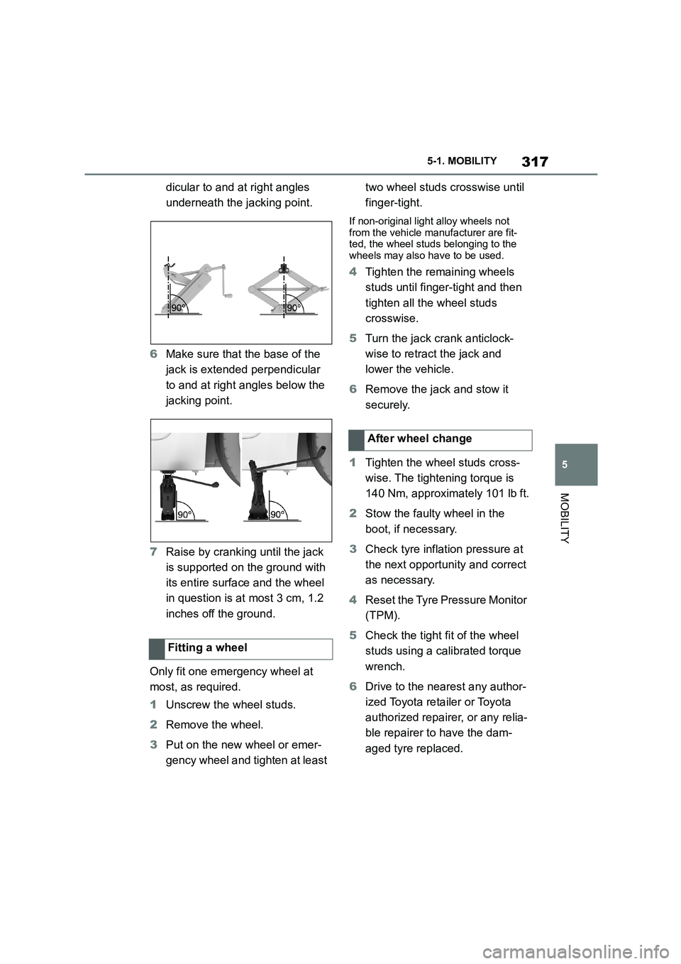
dicular to and at right angles
underneath the jacking point.
6 Make sure that the base of the
jack is extended perpendicular
to and at right angles below the
jacking point.
7 Raise by cranking until the jack
is supported on the ground with
its entire surface and the wheel
in question is at most 3 cm, 1.2
inches off the ground.
Only fit one emergency wheel at
most, as required.
1 Unscrew the wheel studs.
2 Remove the wheel.
3 Put on the new wheel or emer-
gency wheel and tighten at least
two wheel studs crosswise until
finger-tight.
If non-original light alloy wheels not
from the vehicle manufacturer are fit- ted, the wheel studs belonging to the
wheels may also have to be used.
4 Tighten the remaining wheels
studs until finger-tight and then
tighten all the wheel studs
crosswise.
5 Turn the jack crank anticlock-
wise to retract the jack and
lower the vehicle.
6 Remove the jack and stow it
securely.
1 Tighten the wheel studs cross-
wise. The tightening torque is
140 Nm, approximately 101 lb ft.
2 Stow the faulty wheel in the
boot, if necessary.
3 Check tyre inflation pressure at
the next opportunity and correct
as necessary.
4 Reset the Tyre Pressure Monitor
(TPM).
5 Check the tight fit of the wheel
studs using a calibrated torque
wrench.
6 Drive to the nearest any author-
ized Toyota reta iler or Toyota
authorized repairer, or any relia-
ble repairer to have the dam-
aged tyre replaced.
Fitting a wheel
After wheel change
Page 353 of 498
351
5
5-1. MOBILITY
MOBILITY
WA R N I N G
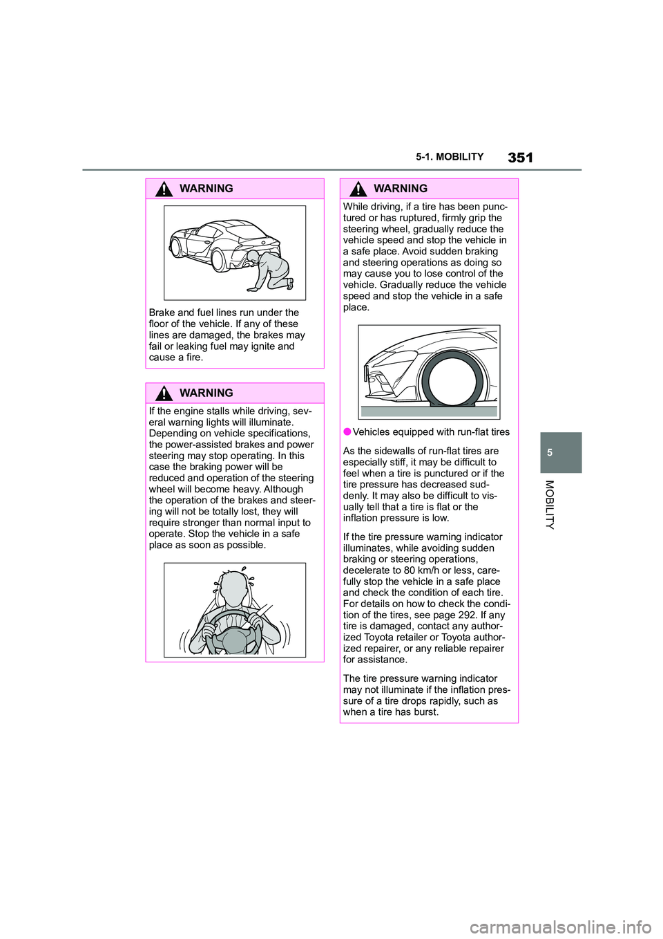
Brake and fuel lines run under the
floor of the vehicle. If any of these
lines are damaged, the brakes may
fail or leaking fuel may ignite and cause a fire.
WA R N I N G
If the engine stalls while driving, sev-
eral warning lights will illuminate. Depending on vehicle specifications,
the power-assisted brakes and power
steering may stop operating. In this case the braking power will be
reduced and operation of the steering
wheel will become heavy. Although the operation of the brakes and steer-
ing will not be totally lost, they will
require stronger than normal input to
operate. Stop the vehicle in a safe place as soon as possible.
WA R N I N G
While driving, if a tire has been punc-
tured or has ruptured, firmly grip the
steering wheel, gradually reduce the vehicle speed and stop the vehicle in
a safe place. Avoid sudden braking
and steering operations as doing so may cause you to lo se control of the
vehicle. Gradually reduce the vehicle
speed and stop the vehicle in a safe
place.
●Vehicles equipped with run-flat tires
As the sidewalls of run-flat tires are
especially stiff, it may be difficult to
feel when a tire is punctured or if the tire pressure has decreased sud-
denly. It may also be difficult to vis-
ually tell that a tire is flat or the inflation pressure is low.
If the tire pressure warning indicator illuminates, while avoiding sudden
braking or steering operations,
decelerate to 80 km /h or less, care- fully stop the vehicle in a safe place
and check the condition of each tire.
For details on how to check the condi- tion of the tires, see page 292. If any
tire is damaged, contact any author-
ized Toyota retailer or Toyota author- ized repairer, or any reliable repairer
for assistance.
The tire pressure warning indicator
may not illuminate if the inflation pres-
sure of a tire drops rapidly, such as when a tire has burst.
Page 475 of 498
473
6
6-1. REFERENCE
REFERENCE
Tire Pressure Monitoring
System
Page 495 of 498

493Alphabetical Index
Spare wheel, see Emergency wheel
..................................................... 318
Special equipment, see Vehicle
equipment ....................................... 4
Speed Limit Assist ....................... 246
Speed Limit Device, see Manual
Speed Limiter ............................. 232
Speed Limit Info ........................... 173
Speed limit, display, see Speed Limit
Info............................................... 173
Speed Limiter, manual ................. 232
Sport displays............................... 180
Sport mode switch ............... 154, 160
Sport programme, Automatic trans-
mission........................................ 154
Sport suspension, see Adaptive vari-
able suspension ......................... 259
SPORT, see Sport mode switch .. 160
Stability control systems ............. 228
Standard equipment, see Vehicle
equipment ....................................... 4
Standard view, Head-Up Display. 182
Standby state, idle state and
drive-ready state .......................... 53
Start/stop button........................... 144
Starting assistance ...................... 357
Starting assistance, see VSC ...... 229
Status Control Display, tyres....... 306
Status information, Toyota Supra
Command...................................... 58
Status of the Owner's Manual ......... 5
Status, vehicle .............................. 181
Steering wheel, adjusting ............ 119
Steering wheel, buttons ................. 46
Steering wheel, see Memory function
..................................................... 119
Storage facilities........................... 274
Storage, see Laying up the vehicle
..................................................... 368
Storage, tyres ............................... 298
Stowing and securing a transported
load .............................................. 276
Stowing heavy transported loads276
Summer tyres, tread ..................... 294
Sun visor ....................................... 269
Supplementary text message ...... 164
Suspension settings, see Sport
mode switch................................160
Switch for driving dynamics, see
Sport mode switch .....................160
Switches, see Driving area ............ 46
Switching on the headlight courtesy
delay feature ................................. 92
Symbols and displays ......................4
T
Tail lights, see Bulbs and lights .. 340
Tailgate, see Boot lid .................... 100
Tank display .................................. 168
Technical changes, see Your own
safety ...............................................6
Technical data ............................... 370
Teleservice call .............................220
Temperature display, see Outside
temperature................................. 169
Temperature, automatic air condi-
tioning .........................................262
Temperature, engine oil ...............169
Tension belt, see Lashing eyes in the
boot..............................................276
Text message, supplementary..... 164
Thiefproof wheel studs ................314
Tilt alarm sensor ...........................104
Tilting down front passenger's mir-
ror, see Automatic parking function
..................................................... 118
Time ................................................. 72
Tire inflation pressure
Maintenance data....................... 374
Tires
Size ............................................374
Tool ................................................ 339
Topping up engine oil................... 325
Torque display, see Sport displays
..................................................... 180
Total weight, permitted................. 371
Touchscreen.................................... 65
Touchscreen, see Operation by
touchscreen .................................. 65