Page 304 of 498

3025-1. MOBILITY
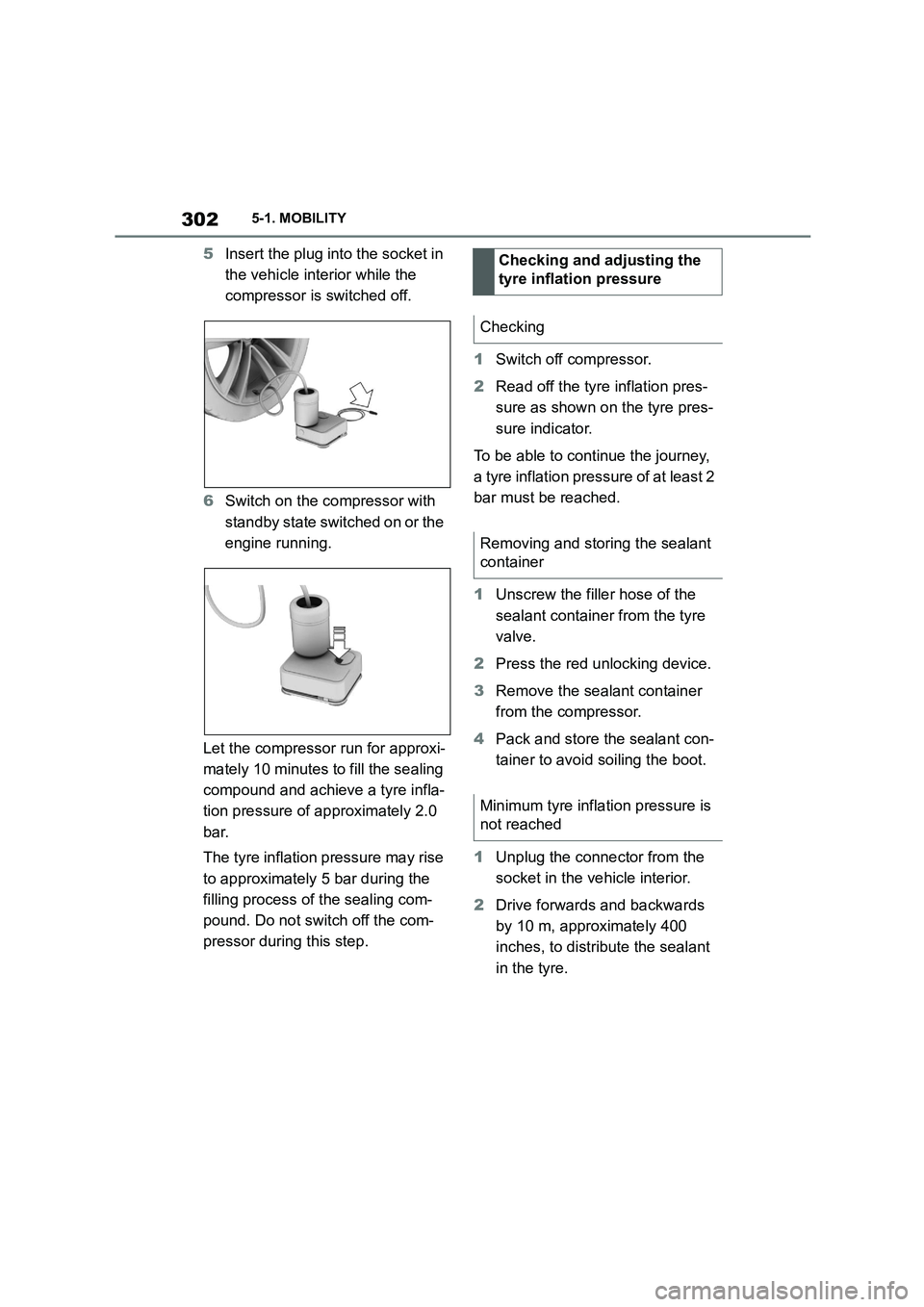
5Insert the plug into the socket in
the vehicle interior while the
compressor is switched off.
6 Switch on the compressor with
standby state switched on or the
engine running.
Let the compressor run for approxi-
mately 10 minutes to fill the sealing
compound and achieve a tyre infla-
tion pressure of approximately 2.0
bar.
The tyre inflation pressure may rise
to approximately 5 bar during the
filling process of the sealing com-
pound. Do not switch off the com-
pressor during this step.
1 Switch off compressor.
2 Read off the tyre inflation pres-
sure as shown on the tyre pres-
sure indicator.
To be able to continue the journey,
a tyre inflation pressure of at least 2
bar must be reached.
1 Unscrew the filler hose of the
sealant container from the tyre
valve.
2 Press the red unlocking device.
3 Remove the sealant container
from the compressor.
4 Pack and store the sealant con-
tainer to avoid soiling the boot.
1 Unplug the connector from the
socket in the vehicle interior.
2 Drive forwards and backwards
by 10 m, approximately 400
inches, to distribute the sealant
in the tyre.
Checking and adjusting the
tyre inflation pressure
Checking
Removing and storing the sealant
container
Minimum tyre inflation pressure is
not reached
Page 319 of 498

317
5
5-1. MOBILITY
MOBILITY
dicular to and at right angles
underneath the jacking point.
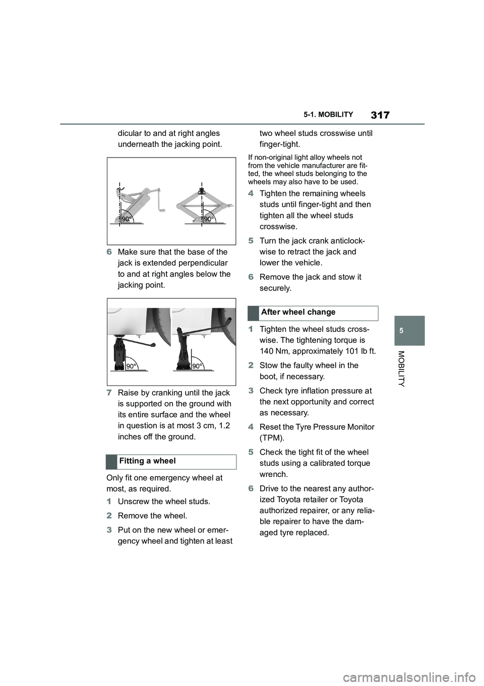
6 Make sure that the base of the
jack is extended perpendicular
to and at right angles below the
jacking point.
7 Raise by cranking until the jack
is supported on the ground with
its entire surface and the wheel
in question is at most 3 cm, 1.2
inches off the ground.
Only fit one emergency wheel at
most, as required.
1 Unscrew the wheel studs.
2 Remove the wheel.
3 Put on the new wheel or emer-
gency wheel and tighten at least
two wheel studs crosswise until
finger-tight.
If non-original light alloy wheels not
from the vehicle manufacturer are fit- ted, the wheel studs belonging to the
wheels may also have to be used.
4 Tighten the remaining wheels
studs until finger-tight and then
tighten all the wheel studs
crosswise.
5 Turn the jack crank anticlock-
wise to retract the jack and
lower the vehicle.
6 Remove the jack and stow it
securely.
1 Tighten the wheel studs cross-
wise. The tightening torque is
140 Nm, approximately 101 lb ft.
2 Stow the faulty wheel in the
boot, if necessary.
3 Check tyre inflation pressure at
the next opportunity and correct
as necessary.
4 Reset the Tyre Pressure Monitor
(TPM).
5 Check the tight fit of the wheel
studs using a calibrated torque
wrench.
6 Drive to the nearest any author-
ized Toyota reta iler or Toyota
authorized repairer, or any relia-
ble repairer to have the dam-
aged tyre replaced.
Fitting a wheel
After wheel change
Page 320 of 498

3185-1. MOBILITY
*: if equipped
In case of a flat tyre, the emergency
wheel can be used as a replace-
ment for the defective tyre. The
emergency wheel is intended for
short-term use until the defective
wheel has been replaced.
Only fit one emergency wheel at
most.
Additionally, regularly check the
tyre inflation pressure of the emer-
gency wheel in the boot and correct
the pressure if necessary.
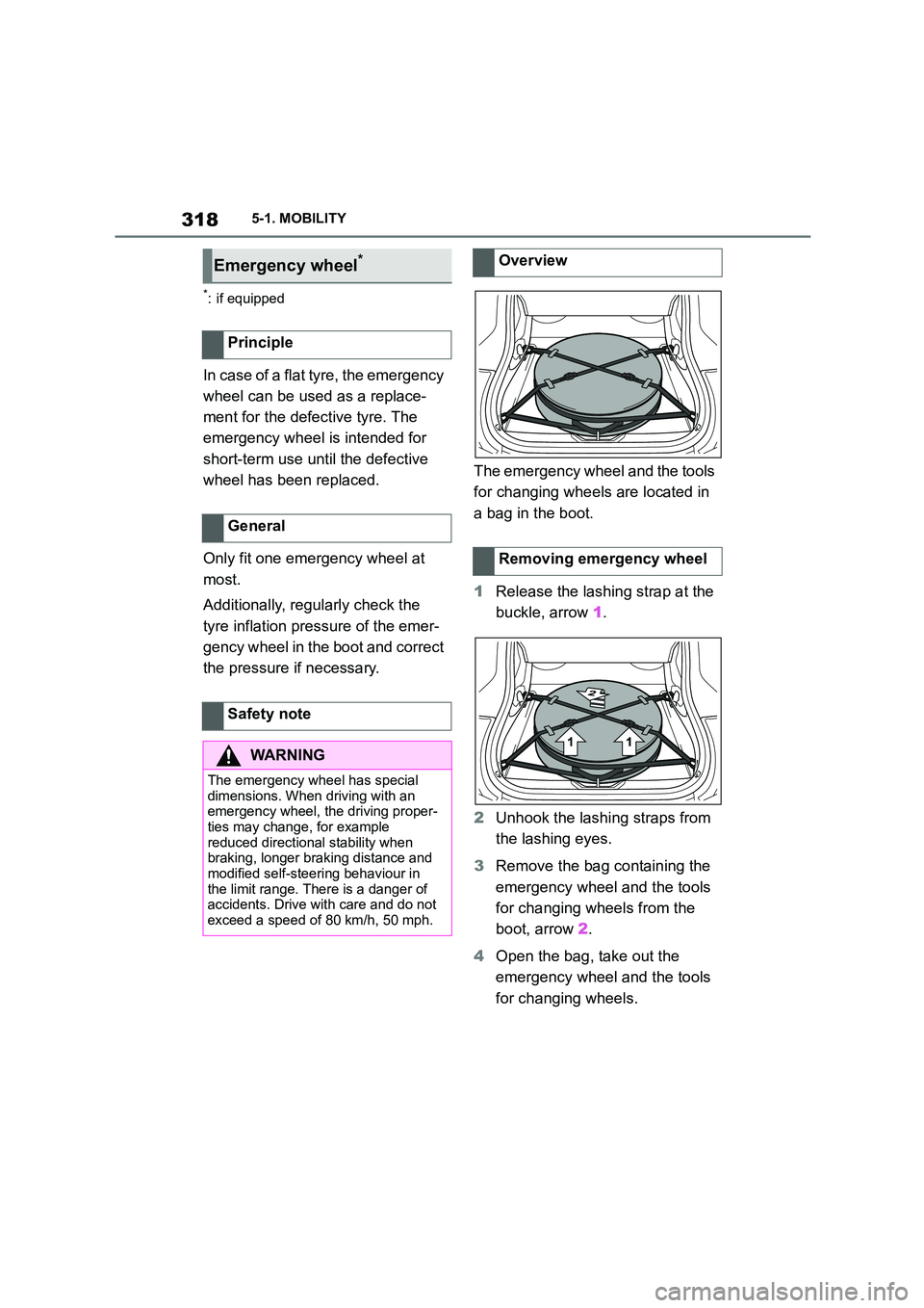
The emergency wheel and the tools
for changing wheels are located in
a bag in the boot.
1 Release the lashing strap at the
buckle, arrow 1.
2 Unhook the lashing straps from
the lashing eyes.
3 Remove the bag containing the
emergency wheel and the tools
for changing wheels from the
boot, arrow 2.
4 Open the bag, take out the
emergency wheel and the tools
for changing wheels.
Emergency wheel*
Principle
General
Safety note
WA R N I N G
The emergency wheel has special
dimensions. When driving with an emergency wheel, the driving proper-
ties may change, for example
reduced directional stability when braking, longer braking distance and
modified self-steering behaviour in
the limit range. There is a danger of accidents. Drive with care and do not
exceed a speed of 80 km/h, 50 mph.
Overview
Removing emergency wheel
Page 321 of 498
319
5
5-1. MOBILITY
MOBILITY
1 Stow the emergency wheel and
the tools for changing wheels in
the bag.
2 Place the bag in the boot.
3 Hook the lashing straps onto the
lashing eyes.
4 Tie the lashing straps. Make
sure that it is seated correctly
and firmly.
This chapter describes all standard,
country-specific and special equip-
ment available for the model series.
It may therefore describe equip-
ment and functions which are not
installed in your vehicle, for exam-
ple on account of the special equip-
ment selected or the country
specification. This also applies to
safety-relevant functions and sys-
tems. Please comply with the rele-
vant laws and regulations when
using the corresponding functions
and systems.
Inserting the emergency
wheel
Engine compar tment
Vehicle equipment
Page 341 of 498

339
5
5-1. MOBILITY
MOBILITY
This chapter describes all standard,
country-specific and special equip-
ment available for the model series.
It may therefore describe equip-
ment and functions which are not
installed in your vehicle, for exam-
ple on account of the special equip-
ment selected or the country
specification. This also applies to
safety-relevant functions and sys-
tems. Please comply with the rele-
vant laws and regulations when
using the corresponding functions
and systems.
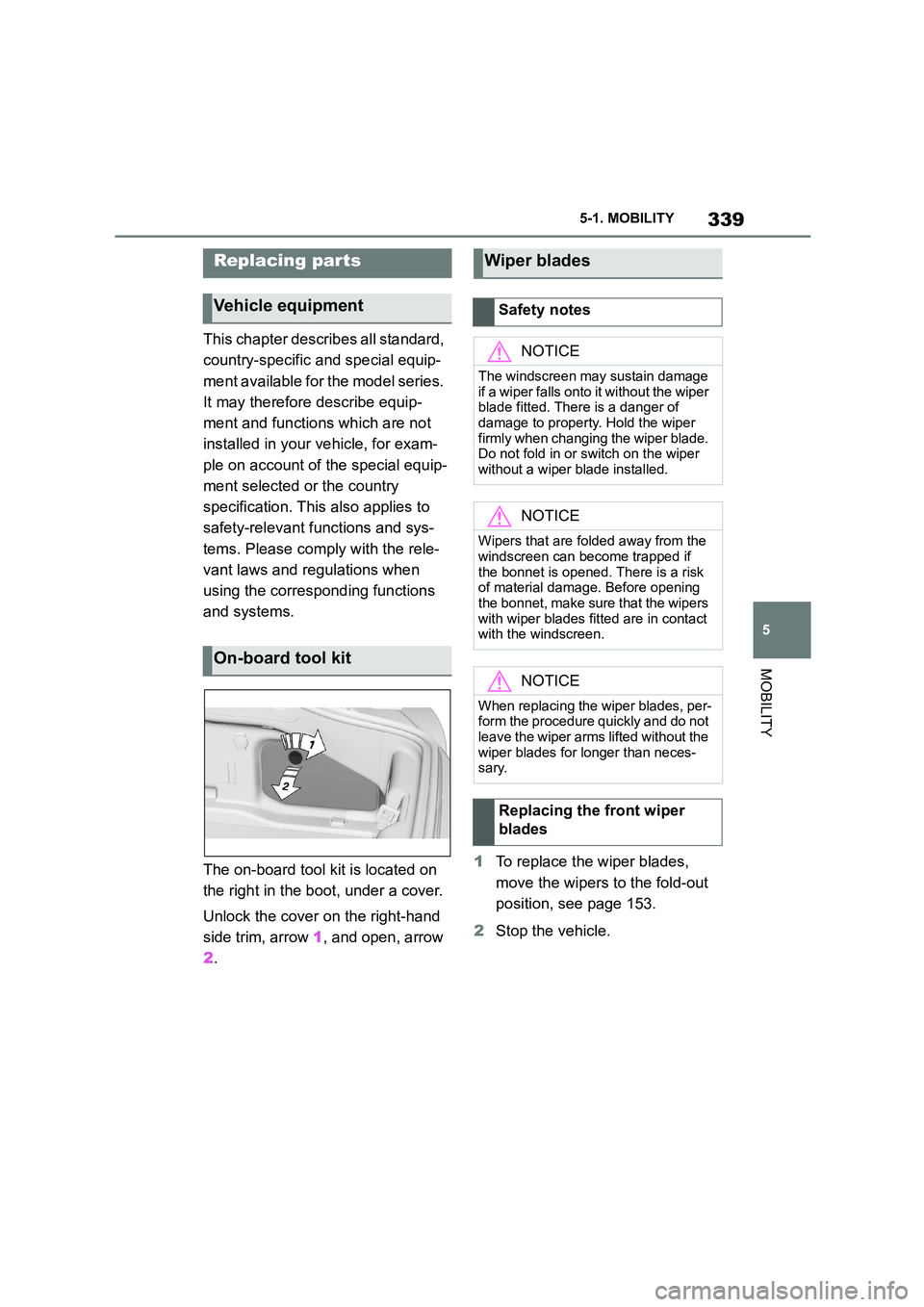
The on-board tool kit is located on
the right in the boot, under a cover.
Unlock the cover on the right-hand
side trim, arrow 1, and open, arrow
2 .
1 To replace the wiper blades,
move the wipers to the fold-out
position, see page 153.
2 Stop the vehicle.
Replacing par ts
Vehicle equipment
On-board tool kit
Wiper blades
Safety notes
NOTICE
The windscreen may sustain damage
if a wiper falls onto it without the wiper
blade fitted. There is a danger of
damage to property. Hold the wiper firmly when changing the wiper blade.
Do not fold in or switch on the wiper
without a wiper blade installed.
NOTICE
Wipers that are folded away from the
windscreen can become trapped if the bonnet is opened. There is a risk
of material damage. Before opening
the bonnet, make sure that the wipers with wiper blades fitted are in contact
with the windscreen.
NOTICE
When replacing the wiper blades, per- form the procedure quickly and do not
leave the wiper arms lifted without the
wiper blades for longer than neces- sary.
Replacing the front wiper
blades
Page 346 of 498
3445-1. MOBILITY
Undo fastenings, arrow, and open
cover.
The fuse box is lo cated at the front
right.
The fuses are located behind a
cover on the right-hand side in the
boot.
Unlock the cover on the right-hand
side trim, arrow 1, and open, arrow
2 .
There are other fuse boxes in the
vehicle. In the event of a fault, con-
tact any authorized Toyota retailer
or Toyota authorized repairer, or
any reliable repairer.
The manufacturer of the vehicle
recommends having fuses changed
by any authorized Toyota retailer or
Toyota authorized repairer, or any
reliable repairer.
BDC
Inside the boot
Other fuse boxes
Replacing fuses
Fuse informations
Page 350 of 498
3485-1. MOBILITY
F69, F70
F203, F206, F209, F271
F1, F3, F39
F36, F61, F62, F67, F68,
F71
F4
F67, F68
SymbolMeaning
VSC Vehicle Stability Con-
trol System
Parking brake
Air conditioning
Defrost the windscreen and
remove condensation
Blower motor, Interior venti-
lation
Rear window heating
Seat heating
Seat setting
Crash-security module
Switching center column,
Light switch element, steer-
ing Operating panel Audio
HiFi amplifier, Video module
TV
Rear-view mirror
Overhead function center,
Exterior door handle elec-
tronics
Instrument cluster
Additional battery: Dual
Accumulator System (DSS)
Fuel pump control electron-
ics, Natural Vacuum Leak
Detection, Gas generator for
battery safety terminal,
Remote control receiver
Electric window opener
Heating and air-condition-
ing system
Vehicle's diagnostic port
(interface)
Interior lights in the boot
Vertical Dynamic platform
Vertical Dynamic platform
Vertical Dynamic platform
SymbolMeaning
Page 351 of 498
349
5
5-1. MOBILITY
MOBILITY
Mono Camera (Kafas)
Head Unit
Active Sound Design
USB Hub
Body Domain Controller
Controller (Toyota Supra
Command)
Electric fan (air cooler), Con-
trolled differential lock
12 V socket, Cigarette
lighter
Interior lights in the boot
Door lock, Exterior door
handle electronics, Telem-
atic Communication Box
Electronic gear box control
Telematic Communication
Box, Exterior door handle
electronics
Electric fan, Rear Power dis-
tributor
Engine control
SymbolMeaning
Switching center column,
Light switch element, Body
Domain Controller
Control panels centre con-
sole, Interior light in the
glove box, Interior light, Inte-
rior light in the sunvisor,
Exterior mirror, Selector
lever
Telematic Communication
Box, Exterior door handle
electronics passenger side
Switcher block driver's door,
Exterior mirror
SymbolMeaning