2022 TOYOTA SUPRA boot
[x] Cancel search: bootPage 258 of 498

2563-1. CONTROLS
Depending on the equipment,
obstacles behind the vehicle are
detected by the Parking Sensors.
Obstacle markers can be shown in
the image from the rear-view cam-
era.
The colour incrementation corre-
sponds to the markings of Parking
Sensors.
With rear-view camera switched on:
1 If necessary, tilt the Controller to
the left.
2 "Camera picture"
3
"Brightness"
"Contrast"
4 Set the desired value.
For further information:
• Cameras, see page 50.
If the camera is deactivated, for
example when the boot lid is
opened, the camera image is dis-
played as grey hatching.
Very low obstacles and higher, pro-
truding objects such as ledges can-
not be detected by the system.
Depending on the equipment, some
assistance functions also take
account of Parking Sensors data.
Observe the notes in the chapter on
Parking Sensors.
The objects shown in the Control
Display may be closer than they
appear. Do not estimate the dis-
tance to objects based on the dis-
play.
*: if equipped
At blind exits or when leaving per-
pendicular parking spaces, the sys-
Obstacle marker
Setting brightness and con-
trast via Toyota Supra Com-
mand
System limits
System limits of the sensors
Deactivated camera
Detection of objects
RCTA (Rear cross traffic
alert) function*
Principle
Page 272 of 498
2703-1. CONTROLS
cal devices when standby state or
drive-ready state is switched on.
The total load of all sockets must
not exceed 140 watts at 12 volts.
To avoid damage to the socket, do
not insert an incompatible plug.
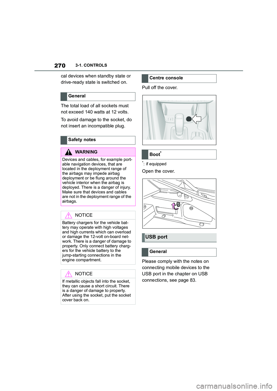
Pull off the cover.
*: if equipped
Open the cover.
Please comply with the notes on
connecting mobile devices to the
USB port in the chapter on USB
connections, see page 83.
General
Safety notes
WA R N I N G
Devices and cables, for example port-
able navigation devices, that are located in the deployment range of
the airbags may impede airbag
deployment or be flung around the vehicle interior when the airbag is
deployed. There is a danger of injury.
Make sure that devices and cables are not in the deployment range of the
airbags.
NOTICE
Battery chargers for the vehicle bat- tery may operate with high voltages
and high currents which can overload
or damage the 12-volt on-board net- work. There is a danger of damage to
property. Only connect battery charg-
ers for the vehicle battery to the jump-starting connections in the
engine compartment.
NOTICE
If metallic objects fall into the socket,
they can cause a short circuit. There
is a danger of damage to property.
After using the socket, put the socket cover back on.
Centre console
Boot*
USB port
General
Page 277 of 498

275
3
3-1. CONTROLS
CONTROLS
This chapter describes all standard,
country-specific and special equip-
ment available for the model series.
It may therefore describe equip-
ment and functions which are not
installed in your vehicle, for exam-
ple on account of the special equip-
ment selected or the country
specification. This also applies to
safety-relevant functions and sys-
tems. Please comply with the rele-
vant laws and regulations when
using the corresponding functions
and systems.
Cupholders
Safety note
WA R N I N G
Unsuitable containers placed in the
cupholders may damage the cuphold- ers or be flung into the interior, for
example in the event of an accident or
when braking or carrying out evasive manoeuvres. Spilt liquids can distract
the driver from the road and lead to
an accident. Hot beverages may damage the cupholders or cause
scalding. There is a danger of injury
or damage to property. Do not force objects into the cupholder. Use light-
weight, sealable and shatterproof
containers. Do not transport hot drinks.
Boot
Vehicle equipment
Loads
Safety notes
WA R N I N G
A high gross vehicle weight can make
the tyres overheat, causing internal
damage and a sudden loss of tyre inflation pressure. Handling charac-
teristics may be adversely affected,
for example reduced directional sta- bility, longer braking distance and
modified steering characteristics.
There is a risk of accident. Please comply with the permitted load index
of the tyre, and do not exceed the per-
mitted gross vehicle weight.
Page 278 of 498
2763-1. CONTROLS
Wrap protective material around
any sharp corners and edges on
the load.
Heavy transported loads: stow
as far forward and as low down
as possible, ideally directly
behind the boot partition.
Small and lightweight loads:
secure with retaining straps, a
luggage net or other suitable
straps.
Large and heavy loads: secure
with lashing straps.
*: if equipped
Equipment for securing the trans-
ported load, for example lashing
straps, tensioning straps or luggage
nets, must be secured to the lash-
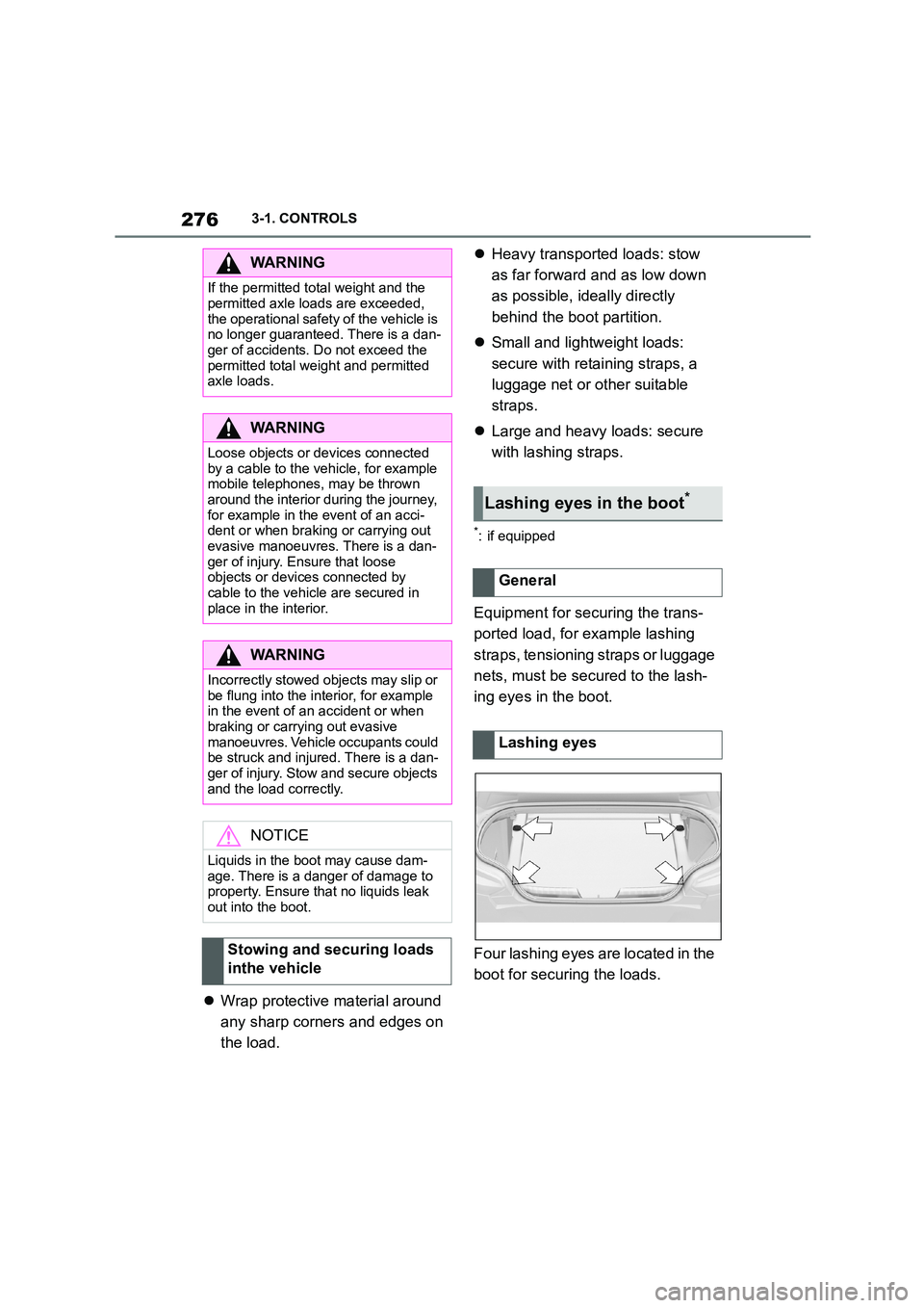
ing eyes in the boot.
Four lashing eyes are located in the
boot for securing the loads.
WA R N I N G
If the permitted total weight and the
permitted axle loads are exceeded,
the operational safety of the vehicle is no longer guaranteed. There is a dan-
ger of accidents. Do not exceed the
permitted total weight and permitted axle loads.
WA R N I N G
Loose objects or devices connected
by a cable to the vehicle, for example mobile telephones, may be thrown
around the interior during the journey,
for example in the event of an acci- dent or when braking or carrying out
evasive manoeuvres. There is a dan-
ger of injury. Ensure that loose objects or devices connected by
cable to the vehicle are secured in
place in the interior.
WA R N I N G
Incorrectly stowed objects may slip or
be flung into the interior, for example
in the event of an accident or when braking or carrying out evasive
manoeuvres. Vehicle occupants could
be struck and injured. There is a dan- ger of injury. Stow and secure objects
and the load correctly.
NOTICE
Liquids in the boot may cause dam- age. There is a danger of damage to
property. Ensure that no liquids leak
out into the boot.
Stowing and securing loads
inthe vehicle
Lashing eyes in the boot*
General
Lashing eyes
Page 279 of 498
277
3
3-1. CONTROLS
CONTROLS
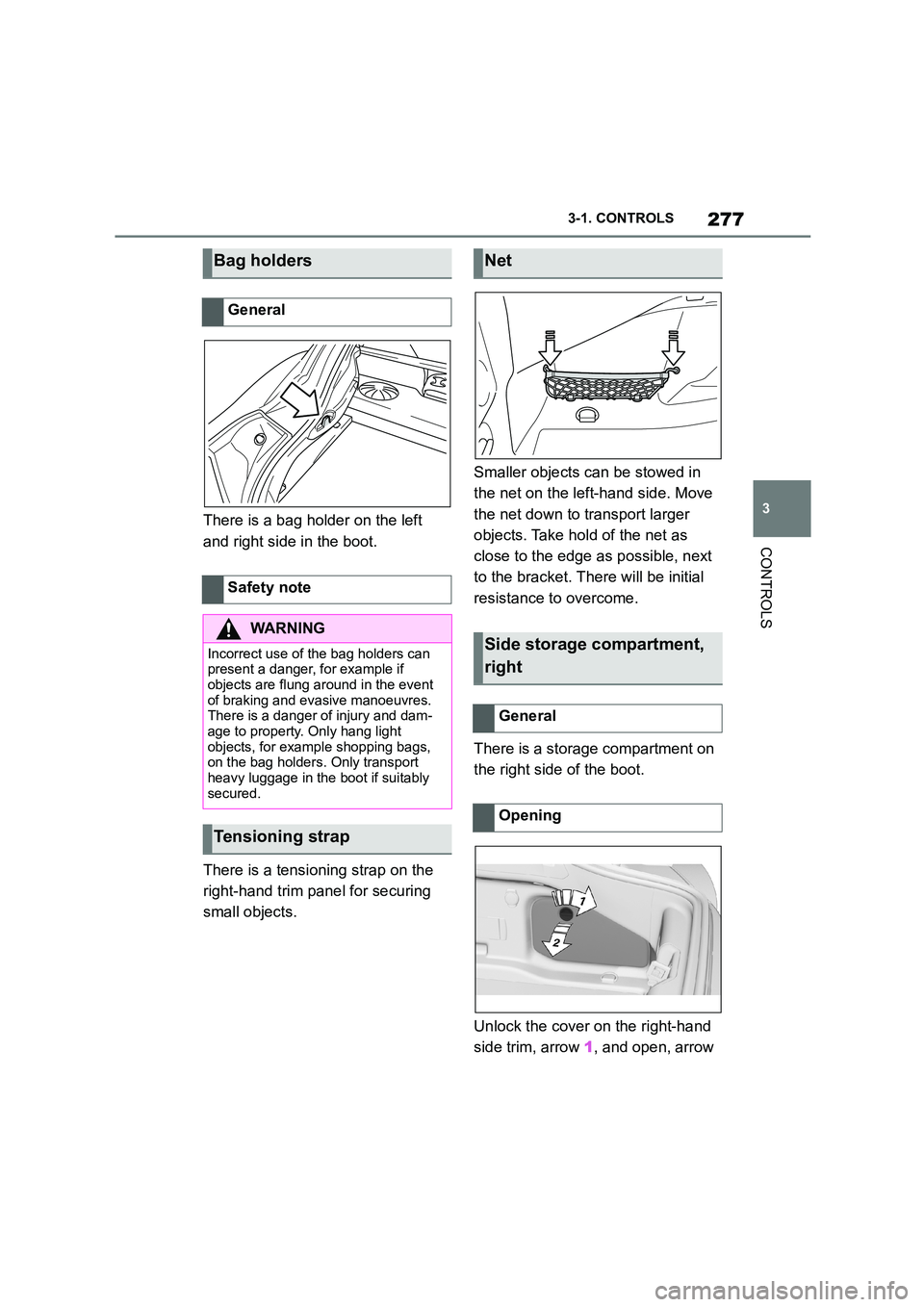
There is a bag holder on the left
and right side in the boot.
There is a tensioning strap on the
right-hand trim panel for securing
small objects.
Smaller objects can be stowed in
the net on the left-hand side. Move
the net down to transport larger
objects. Take hold of the net as
close to the edge as possible, next
to the bracket. Th ere will be initial
resistance to overcome.
There is a storage compartment on
the right side of the boot.
Unlock the cover on the right-hand
side trim, arrow 1, and open, arrow
Bag holders
General
Safety note
WA R N I N G
Incorrect use of the bag holders can
present a danger, for example if
objects are flung around in the event of braking and evasive manoeuvres.
There is a danger of injury and dam-
age to property. Only hang light objects, for example shopping bags,
on the bag holders. Only transport
heavy luggage in the boot if suitably secured.
Tensioning strap
Net
Side storage compartment,
right
General
Opening
Page 283 of 498
281
4
4-1. DRIVING HINTS
DRIVING HINTS
Brake discs and pads only achieve
their full effectiveness after approxi-
mately 500 km, 300 miles. Drive
moderately during this running-in
period.
Please comply with the running-in
procedures again if the compo-
nents previously referred to are
renewed.
The exhaust gas particle filter col-
lects soot particles. The soot parti-
cles are burned at high
Brake system
After fitting new parts
General driving information
Closing the boot lid
Safety note
WA R N I N G
When open, the boot lid protrudes above the vehicle, and in the event of
an accident, braking or evasive
manoeuvres, it can endanger vehicle occupants and other road users, or
damage the vehicle. Exhaust fumes
may also enter the passenger com- partment. There is a danger of injury
or damage to property. Do not drive
with the boot lid open.
Ice on the windows
NOTICE
The window lowers a little when the
door handle is pulled. If there is frost, the window may freeze up and cannot
then be lowered. There is a risk of
material damage. Make sure that the window lowers when the door handle
is pulled. Remove any snow or ice
from the window. Do not open the
door by force.
Hot exhaust system
WA R N I N G
High temperatures can be generated
under the body during driving, for example because of the exhaust sys-
tem. Contact with the exhaust system
can lead to burns. There is a risk of injury. Do not touch the hot exhaust
system, including th e exhaust pipe.
WA R N I N G
If flammable materials, for example leaves or grass, come into contact
with hot parts of the exhaust system,
these materials can catch fire. There is a risk of fire and injury. Never
remove the heat shields fitted here or
apply underbody protection to them. Make sure that when driving, idling or
parking, no flammable materials can
come into contact with hot vehicle parts.
Exhaust gas particle filter
Principle
Page 295 of 498
293
5
5-1. MOBILITY
MOBILITY
ized Toyota reta iler or Toyota
authorized repairer, or any reliable
repairer.
The tyre inflation pressure appropri-
ate for the respective load condi-
tions should be used. For example,
if the vehicle is partially loaded, use
the tyre inflation pressure specified
for a partially loaded vehicle.
The current tire pr essure of each
installed wheel can be displayed on
the control display.
To ensure that they are displayed
correctly, the tyre sizes must be
stored in the system and must have
been set, see page 304, for the
mounted tyres.
The current tyre inflation pressure
value is shown on each tyre.
Tyres heat up while driving. The
tyre inflation pressure increases
with the temperature of the tyre.
Tyres have a natural, uniform loss
of tyre inflation pressure.
Inflating devices can display a pres-
sure that may be up to 0.1 bar too
low.
The tyre inflation pressure inscrip-
tions on the tyre inflation pressure
sign on the door pillar only relate to
cold tyres or tyres at the same tem-
perature as the ambient tempera-
ture.
Only check the tyre inflation pres-
sures when the tyres are cold, i.e.:
• If the vehicle has been driven a
distance of no more than 2 km,
1.25 miles.
• If the vehicle has not moved
again for at least 2 hours after a
journey.
Regularly check the tyre inflation
pressure of the emergency wheel in
the boot and correct the pressure if
necessary.
1 Determine the specified tyre
inflation pressures for the tyres
installed on the vehicle.
For Australia/New Zealand
WA R N I N G
The inflation pressures on the tyre
label are applicable only for tyres
explicitly mentioned on the label. Inflation pressures for tyres that may
be covered by the label – by size,
speed category and load rating/load index – but not explicitly mentioned
on the label may be different. Please
obtain adequate inflation pressures in accordance with the tyre manufac-
turer's specifications from your tyre
dealer.
On the Control Display
Checking the tyre inflation
pressure
General
Checking using tyre inflation pres-
sure inscriptions on the door pillar
Page 302 of 498
3005-1. MOBILITY
check the tyre inflation pressure.
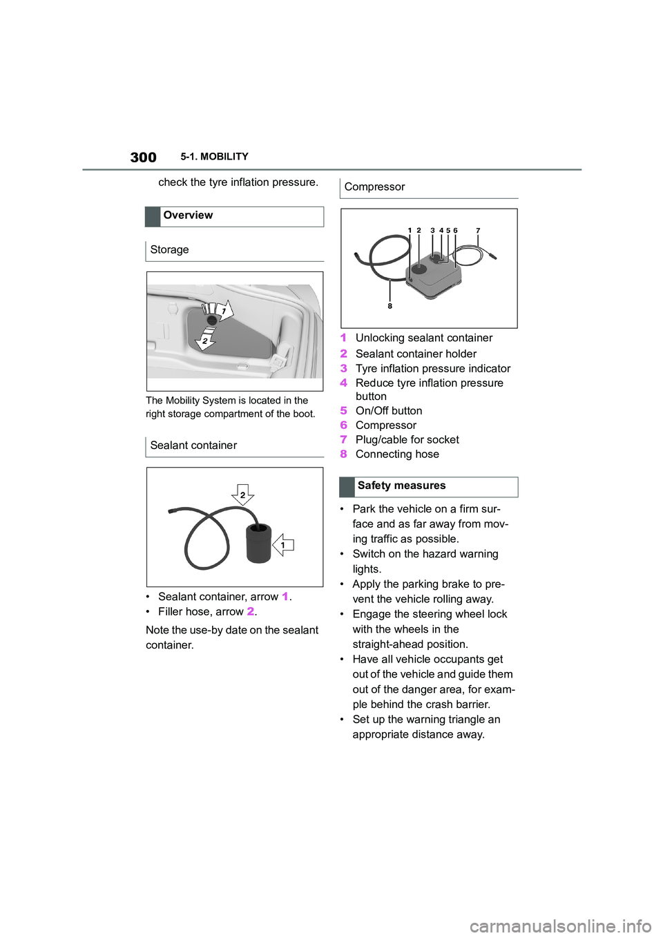
The Mobility System is located in the
right storage compartment of the boot.
• Sealant container, arrow 1.
• Filler hose, arrow 2.
Note the use-by date on the sealant
container.
1 Unlocking sealant container
2 Sealant container holder
3 Tyre inflation pressure indicator
4 Reduce tyre inflation pressure
button
5 On/Off button
6 Compressor
7 Plug/cable for socket
8 Connecting hose
• Park the vehicle on a firm sur-
face and as far away from mov-
ing traffic as possible.
• Switch on the hazard warning
lights.
• Apply the parking brake to pre-
vent the vehicle rolling away.
• Engage the steering wheel lock
with the wheels in the
straight-ahead position.
• Have all vehicle occupants get
out of the vehicle and guide them
out of the danger area, for exam-
ple behind the crash barrier.
• Set up the warning triangle an
appropriate distance away.
Overview
Storage
Sealant container
Compressor
Safety measures