2022 TOYOTA SUPRA steering
[x] Cancel search: steeringPage 162 of 498
1603-1. CONTROLS
been selected.
3 Press the button.
TRACTION will be displayed on the instrument cluster and the VSC OFF
indicator lamp will illuminate.
4 Select the D selector lever posi-
tion.
5 Firmly depress the brake pedal
with your left foot.
6 Fully depress and hold the
accelerator pedal at the kick-
down position.
A flag symbol will be shown in the instrument cluster.
7 The engine speed will be
adjusted for launching. Release
the brake pedal within 3 sec-
onds.
Once Launch Control has been
used, the transmission requires
approximately 5 minutes to cool
down before Launch Control can be
used again. Launch Control adapts
to the ambient conditions when
used again.
To support driving stability, re-acti-
vate Vehicle Stab ility Control, VSC
as soon as possible.
An experienced driver may be able
to achieve better acceleration val-
ues in VSC OFF mode.
The sport mode switch influences
the driving dynamics characteristics
of the vehicle.
The following systems are influ-
enced, for example:
Engine characteristics.
Automatic transmission.
Adaptive variable suspension.
Steering.
Display in the instrument cluster.
Cruise Control. Using again during a journey
After using Launch Control
System limits
Sport mode switch
Principle
General
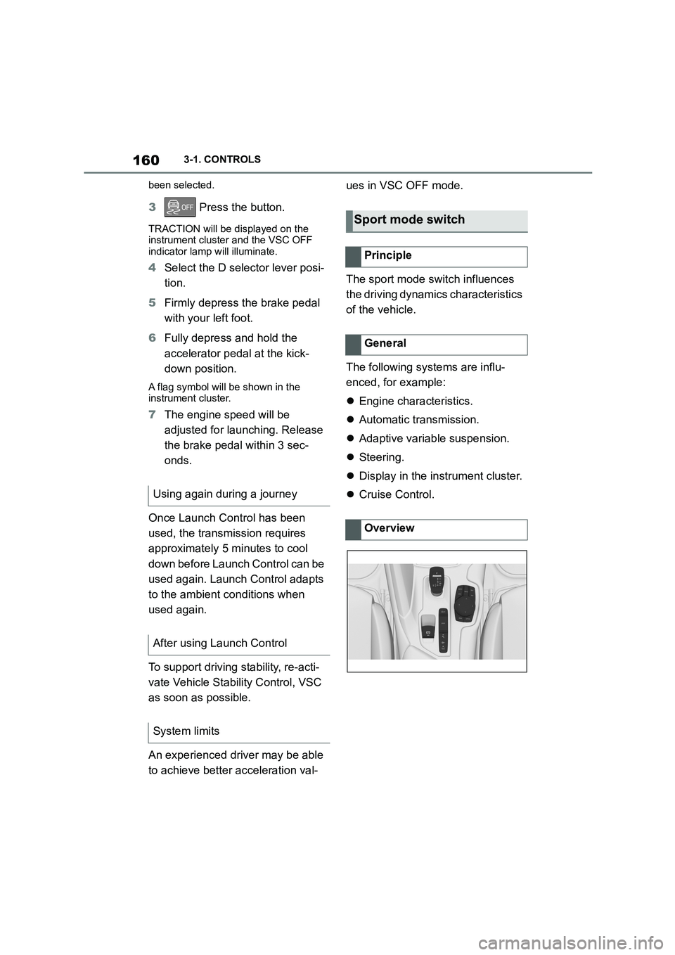
Overview
Page 169 of 498

167
3
3-1. CONTROLS
CONTROLS
Steering system
The steering system may
be faulty.
Have the system checked
by any authorized Toyota
retailer or Toyota author-
ized repairer, or any relia-
ble repairer.
Emissions
Engine malfunction.
Have the vehicle checked
by any authorized Toyota
retailer or Toyota author-
ized repairer, or any relia-
ble repairer.
Socket for on-board diag-
nosis, see page 332.
Rear fog light
Rear fog light is switched
on.
Rear fog light, see page
190.
Green lights
Turn indicator
The turn indicator is
switched on.
If the indicator lamp
flashes more rapidly than
usual, a turn signal light
has failed.
Turn indicators, see page
150.
Side lights
The side lights are
switched on.
Side lights/low-beam
headlights, see page 185.
Low-beam headlights
Low-beam headlights are
switched on.
Side lights/low-beam
headlights, see page 185.
Lane Departure Warning
If the indicator lamp is illu-
minated: the system is
switched on. At least one
lane marking has been
detected and warnings
can be issued on at least
one side of the vehicle.
Lane Departure Warning,
see page 216.
Page 179 of 498
177
3
3-1. CONTROLS
CONTROLS
to the standard.
If signs are detected that apply to
a parallel road.
In the case of country-specific
signs or road layouts.
During the camera calibration
process immediately after vehi-
cle delivery.
The display can be operated when
necessary.
Entertainment source.
Current audio source.
Last calls list.
If applicable, the relevant menu is
opened on the Control Display.
Items displayed may differ depend-
ing on the specifications of the vehi-
cle.
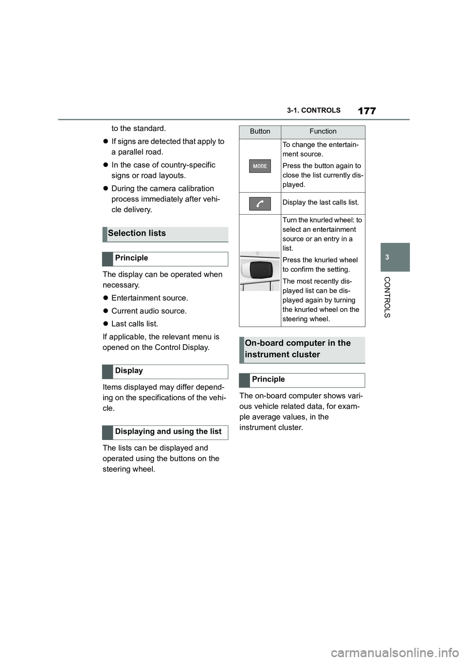
The lists can be displayed and
operated using the buttons on the
steering wheel.
The on-board computer shows vari-
ous vehicle related data, for exam-
ple average values, in the
instrument cluster.
Selection lists
Principle
Display
Displaying and using the list
ButtonFunction
To change the entertain-
ment source.
Press the button again to
close the list currently dis-
played.
Display the last calls list.
Turn the knurled wheel: to
select an entertainment
source or an entry in a
list.
Press the knurled wheel
to confirm the setting.
The most recently dis-
played list can be dis-
played again by turning
the knurled wheel on the
steering wheel.
On-board computer in the
instrument cluster
Principle
Page 186 of 498
1843-1. CONTROLS
cover.
Dirt on the inside or outside of
the windscreen.
Sunglasses with certain polarisa-
tion filters.
Wet road.
Unfavourable lighting conditions.
If the image is di storted, have the
default settings checked by any
authorized Toyota retailer or Toyota
authorized repairer, or any reliable
repairer.
The windscreen is an integral part
of the system.
The shape of the windscreen ena-
bles a sharp image to be projected.
A film in the windscreen prevents
double images occurring.
Therefore if the special windscreen
needs to be replaced, it is strongly
recommended that this be carried
out by any authorized Toyota
retailer or Toyota authorized
repairer, or any reliable repairer if
required.
This chapter describes all standard,
country-specific and special equip-
ment available for the model series.
It may therefore describe equip-
ment and functions which are not
installed in your vehicle, for exam-
ple on account of the special equip-
ment selected or the country
specification. This also applies to
safety-relevant functions and sys-
tems. Please comply with the rele-
vant laws and regulations when
using the corresponding functions
and systems.
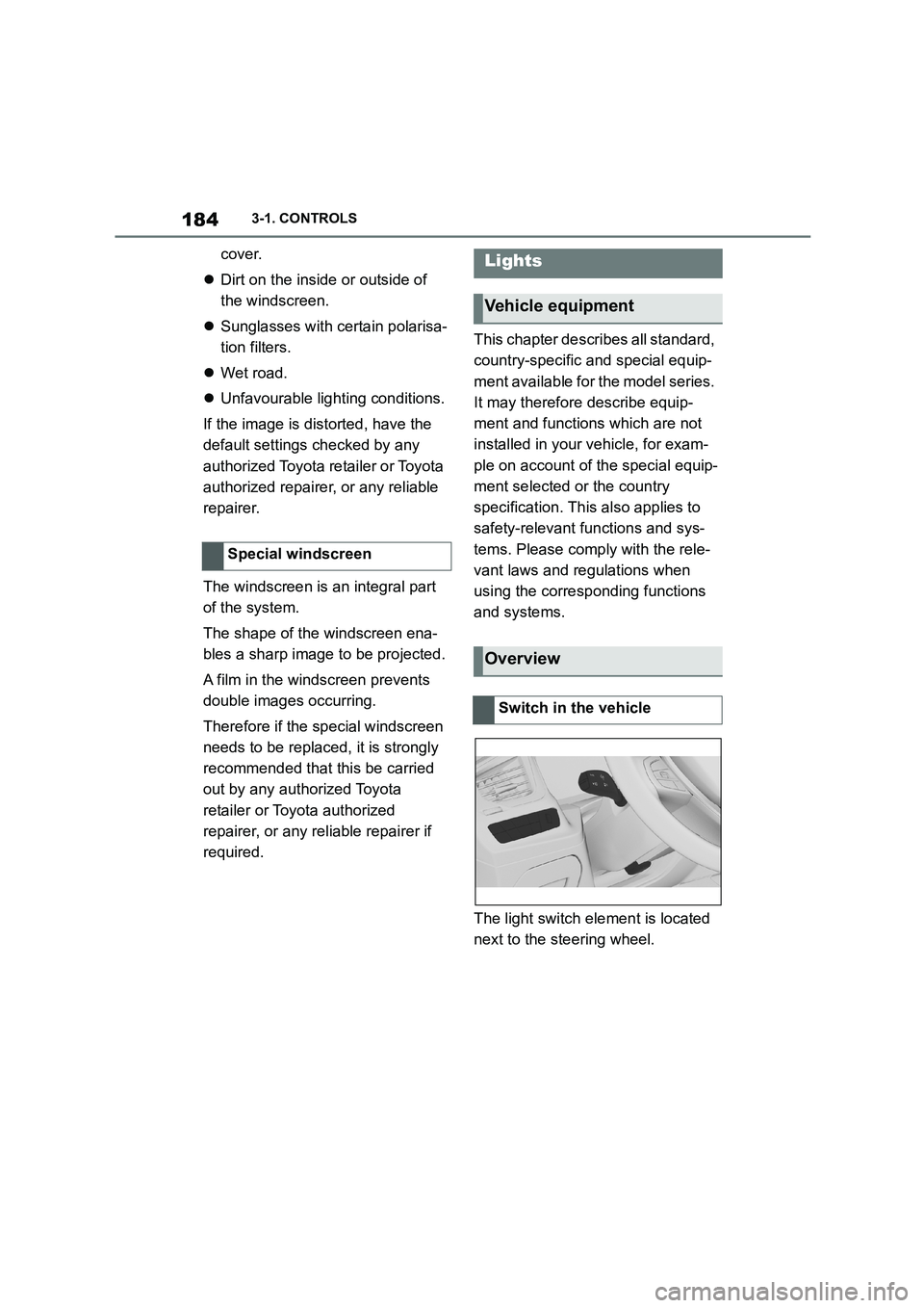
The light switch element is located
next to the steering wheel.
Special windscreen
Lights
Vehicle equipment
Overview
Switch in the vehicle
Page 190 of 498
1883-1. CONTROLS
4"Daytime driving lights"
Variable light distribution enables
even better illumination of the car-
riageway.
The light distribution is automati-
cally adapted to the speed.
If equipment includes a navigation
system, the light distribution is
automatically adapted depending
on the navigation data and speed.
The illuminated area of the
low-beam headlights is extended at
the sides.
The range of the low-beam head-
lights is increased.
In sharp turns up to a specified
speed, for example in hairpin bends
or when turning off, a cornering
light is added to illuminate the
inside area of the bend.
The cornering light is activated
automatically depending on the
steering angle or use of the turn
indicators.
The cornering light may be acti-
vated automatically when driving in
reverse, irrespective of the steer-
ing angle.
Automatic high-beam detects other
road users in good time and acti-
vates or deactivates the high beam
depending on the traffic situation.
Automatic high-beam ensures that
the high-beam headlights are
switched on when the traffic situa-
tion allows. The high-beam head-
lights are not switched on by the
system in the low speed range.
The system responds to the lights
from oncoming traffic and traffic
driving ahead of you, and to ambi-
ent lighting, for example in built-up
areas.
The high-beam headlights can be
switched on and off manually at any
time.
If the vehicle is equipped with daz-
zle-free Automatic high-beam, the
high-beam headlights are not
switched off for oncoming vehicles
or vehicles driving ahead of you;
instead, the system masks those
Variable light distribution
Principle
General
City light
Motorway beam pattern
Cornering light
Automatic high-beam
Principle
General
Page 196 of 498
1943-1. CONTROLS
collision, for example, in minor acci-
dents.
Keep your distance from the
airbags.
Always grip the steering wheel
on the steering wheel rim. Place
your hands in the 3 o'clock and 9
o'clock positions to minimise the
risk of injury to hands or arms
when the airbag deploys.
Adjust the seat and steering
wheel so the driver can reach
over the steering wheel diago-
nally. Select the settings so that,
when reaching over, the shoul-
ders stay in contact with the
backrest and the upper body
stays as far away from the steer-
ing wheel as possible.
Make sure that the front-seat
passenger is sitting correctly, i.e.
with their feet and legs in the
footwell, not resting on the dash-
board.
Make sure that vehicle occu-
pants keep their head away from
the side airbag.
Do not place any other persons,
pets or objects between the
airbags and occupants.
Keep the dashboard and wind-
screen area on the passenger
side clear, for example do not
attach adhesive foil or covers
and do not fit brackets for navi-
gation devices or mobile tele-
phones.
Do not glue the airbag covers
and do not cover or modify them
in any way.
Do not use the front airbag cover
on the front passenger's side as
a tray.
Do not install seat covers, cush-
ions or other objects on the front
seats if they are not specifically
designed for use on seats with
integral side airbags.
Do not hang items of clothing for
example coats or jackets over
the backrests.
Do not modify individual compo-
nents of the system or its wiring
in any way. This also applies to
the covers of the steering wheel,
the dashboard and seats.
Do not dismantle the airbag sys-
tem.
Even if all this information is
observed, depending on the cir-
cumstances in which an accident
occurs, certain injuries as a result
of contact with the airbag cannot be
Notes on achieving optimum
airbag effectiveness
WA R N I N G
If the seat position is wrong or the
deployment area of the airbag is
restricted, the airbag system cannot provide the intended protection or
may cause additional injuries when it
deploys. There is a danger of injury or even death. Observe the following to
achieve optimum protective effect.
Page 198 of 498
1963-1. CONTROLS
3Readjust the desired seat posi-
tion.
The calibration is concluded when
the message on the Control Display
disappears.
If the message is still displayed,
repeat the calibration.
If the message still does not go out
after repeated calibration, have the
system checked as soon as possi-
ble.
The airbags are not designed to be
used in place of the seat belts.
The SRS front airbags and SRS
knee airbags are designed to sup-
plement the seat belts, not be used
in place of them, to increase their
effectiveness as an occupant pro-
tection device.
SRS is an acronym for Supplemental
Restraint System
In the event of a collision, the seat
belts restrain the occupants in their
seats, but if the impact of the colli-
sion is especially severe, there is
danger of an occupant’s head and
chest contacting the steering
wheel, dashboard and windshield.
In this case, the SRS front airbags
and SRS knee airbags deploy
(inflate), instantly creating an air
cushion to help reduce the impact
on the occupants and restrain them
from contacting the steering wheel,
etc. with their head, chest and
knees.
The SRS front air bags and SRS
knee airbags deploy only when an
impact exceeding a certain thresh-
old is detected. In a collision, even
if the impact is severe enough to
cause the vehicle body to deform,
the SRS airbags may not deploy if
the impact of the collision is suffi-
ciently dispersed by the crash
structures of the vehicle body. If the
force of the collision does not cause
the airbags to deploy, the seatbelts
will protect the occupants.
When an airbag deploys, as it will
inflate nearly instantly, it may
impact an occupant and cause an
injury, or the loud noise emitted by
ignition or deployment may cause
temporary partial loss of hearing.
Also, as an airbag and nearby parts
will be extremely hot after the
airbag deploys, touching them may
cause burns. For these reasons,
deployment of the airbags is not
entirely risk free. Therefore, in
order to reduce this risk, the
airbags are designed to only deploy
when additional reduction of the
impact applied to the occupants in
a collision is necessary.
SRS front airbag/SRS knee
airbag
WA R N I N G
Wear the seatbelt correctly and sit
with the correct posture.
Page 199 of 498
197
3
3-1. CONTROLS
CONTROLS
When the vehicle is involved in a
frontal collision which exceeds a
threshold equivale nt to colliding
with a concrete wall which does not
move or deform
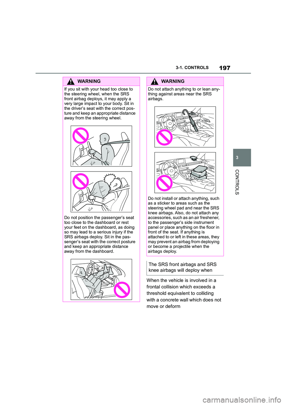
WA R N I N G
If you sit with your head too close to
the steering wheel, when the SRS
front airbag deploys, it may apply a very large impact to your body. Sit in
the driver’s seat with the correct pos-
ture and keep an appropriate distance away from the steering wheel.
Do not position the passenger’s seat
too close to the dashboard or rest your feet on the dashboard, as doing
so may lead to a serious injury if the
SRS airbags deploy. Sit in the pas- senger’s seat with the correct posture
and keep an appropriate distance
away from the dashboard.
WA R N I N G
Do not attach anything to or lean any-
thing against areas near the SRS
airbags.
Do not install or attach anything, such
as a sticker to areas such as the
steering wheel pad and near the SRS knee airbags. Also, do not attach any
accessories, such as an air freshener,
to the passenger’s side instrument panel or place anything on the floor in
front of the seat. If anything is
attached to or left in these areas, they may prevent an airbag from deploying
or become a projectile when the
airbags deploy.
The SRS front airbags and SRS
knee airbags will deploy when