2021 RAM PROMASTER CITY light
[x] Cancel search: lightPage 194 of 280

192IN CASE OF EMERGENCY
Interior Fuses
The interior fuse panel is part of the Body
Control Module (BCM) and is located on the
driver's side under the instrument panel.
Fuse Panel CoverFuse Panel Cavity Locations
CavityMini Fuse Description
F535 Amp Beige KL 30 (+30) - IPC, FTM
F38 20 Amp Yellow Central Doors Locking
F36 15 Amp Blue KL 30 (+30) - TPMS, EOBD, HVAC, Radio, USB, SGW
F43 15 Amp Blue Bi-Directional Washer Pump
F48 20 Amp Yellow Passenger Power Windows
F50 7.5 Amp Brown KL 15 (+15) - Air-Bag
F51 7.5 Amp Brown KL 15 (+15) - External Mirror Adjustment Command, HVAC, RVC, HWB Coils
F37 5 Amp Beige KL 15 (+15) - Brake Pedal Switch (N.O.), IPC, Brake Pedal Switch (N.C.)
F49 5 Amp Beige KL 15 (+15) - PAM, CSS Lighting, TTM, SGW, and Heaters Light, ECM Backlighting
F31 5 Amp Beige KL 15a (INT A) - HWB, MCO
F47 20 Amp Yellow Driver Power Windows
21_VM_OM_EN_USC_t.book Page 192
Page 201 of 280
IN CASE OF EMERGENCY199
3. Turn the handle on the jack screw to the
right until the jack head is properly engaged
in the described location. Do not raise the
vehicle until you are sure the jack is
securely engaged.
4. Raise the vehicle by turning the jack screw to the right until the tire just clears the
surface and enough clearance is obtained
to install the spare tire. Minimum tire lift
provides maximum stability.
5. Remove the wheel lug bolts. For vehicles with wheel covers, remove the cover from
the wheel by hand. Do not pry the wheel
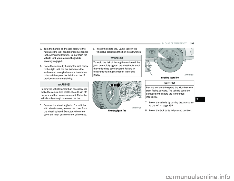
cover off. Then pull the wheel off the hub. 6. Install the spare tire. Lightly tighten the
wheel lug bolts using the bolt install wrench.
Mounting Spare Tire Installing Spare Tire
7. Lower the vehicle by turning the jack screw to the left Ú page 255.
8. Lower the jack to its fully-closed position.
WARNING!
Raising the vehicle higher than necessary can
make the vehicle less stable. It could slip off
the jack and hurt someone near it. Raise the
vehicle only enough to remove the tire.
WARNING!
To avoid the risk of forcing the vehicle off the
jack, do not fully tighten the wheel bolts until
the vehicle has been lowered. Failure to
follow this warning may result in serious
injury.
CAUTION!
Be sure to mount the spare tire with the valve
stem facing outward. The vehicle could be
damaged if the spare tire is mounted
incorrectly.
7
21_VM_OM_EN_USC_t.book Page 199
Page 203 of 280
IN CASE OF EMERGENCY201
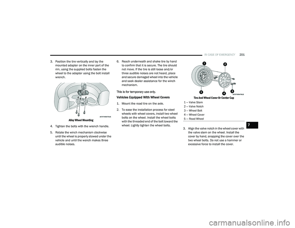
3. Position the tire vertically and lay the
mounted adapter on the inner part of the
rim, using the supplied bolts fasten the
wheel to the adapter using the bolt install
wrench.
Alloy Wheel Mounting
4. Tighten the bolts with the wrench handle.
5. Rotate the winch mechanism clockwise until the wheel is properly stowed under the
vehicle and until the wench makes three
audible noises. 6. Reach underneath and shake tire by hand
to confirm that it is secure. The tire should
not move. If the tire is still loose and/or
three audible noises are not heard, place
and secure damaged wheel into the vehicle
and seek dealer assistance for the winch
mechanism.
This is for temporary use only.
Vehicles Equipped With Wheel Covers
1. Mount the road tire on the axle.
2. To ease the installation process for steel wheels with wheel covers, install two wheel
bolts on the wheel. Install the wheel bolts
with the threaded end of the bolt toward the
wheel. Lightly tighten the wheel bolts.
Tire And Wheel Cover Or Center Cap
3. Align the valve notch in the wheel cover with the valve stem on the wheel. Install the
cover by hand, snapping the cover over the
two wheel bolts. Do not use a hammer or
excessive force to install the cover.1 — Valve Stem
2 — Valve Notch
3 — Wheel Bolt
4 — Wheel Cover
5 — Road Wheel
7
21_VM_OM_EN_USC_t.book Page 201
Page 204 of 280
202IN CASE OF EMERGENCY
4. Install the remaining wheel bolts with the
threaded end of the wheel bolt toward the
wheel. Lightly tighten the wheel bolts.
5. Lower the vehicle to the ground by turning the jack handle counterclockwise.
6. Finish tightening the wheel bolts. Push down on the wrench while holding at the
end of the handle for increased leverage.
Tighten the wheel bolts in a star pattern
until each wheel bolt has been tightened
twice Ú page 255.
7. After 25 miles (40 km) check the wheel bolt torque with a torque wrench to ensure that
all wheel bolts are properly seated against
the wheel.TIRE SERVICE KIT — IF EQUIPPED
Small punctures up to ¼ inch (6 mm) in the tire
tread can be sealed with Tire Service Kit.
Foreign objects (e.g., screws or nails) should not
be removed from the tire. Tire Service Kit can be
used in outside temperatures down to
approximately -4°F (-20°C).
This kit will provide a temporary tire seal,
allowing you to drive your vehicle up to
100 miles (160 km) with a maximum speed of 50 mph (80 km/h).
Tire Service Kit Storage
The Tire Service Kit is located under the
passenger seat.
Tire Service Kit Storage
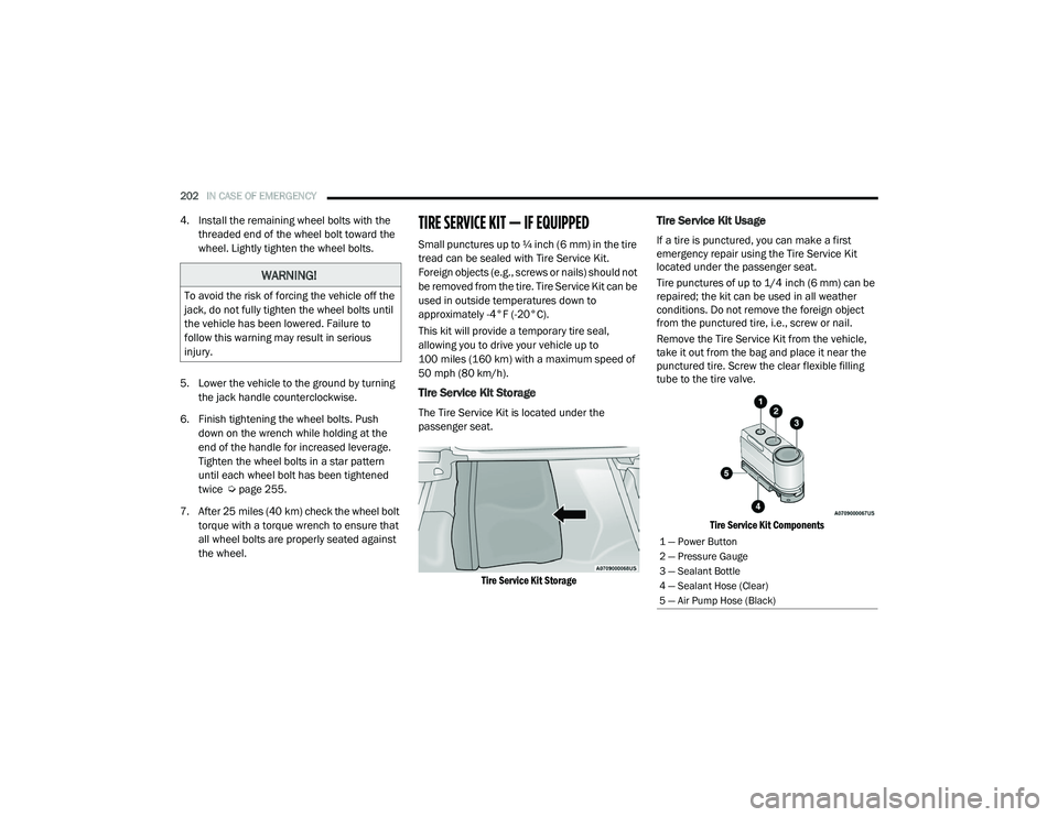
Tire Service Kit Usage
If a tire is punctured, you can make a first
emergency repair using the Tire Service Kit
located under the passenger seat.
Tire punctures of up to 1/4 inch (6 mm) can be
repaired; the kit can be used in all weather
conditions. Do not remove the foreign object
from the punctured tire, i.e., screw or nail.
Remove the Tire Service Kit from the vehicle,
take it out from the bag and place it near the
punctured tire. Screw the clear flexible filling
tube to the tire valve.
Tire Service Kit Components
WARNING!
To avoid the risk of forcing the vehicle off the
jack, do not fully tighten the wheel bolts until
the vehicle has been lowered. Failure to
follow this warning may result in serious
injury.
1 — Power Button
2 — Pressure Gauge
3 — Sealant Bottle
4 — Sealant Hose (Clear)
5 — Air Pump Hose (Black)
21_VM_OM_EN_USC_t.book Page 202
Page 207 of 280

IN CASE OF EMERGENCY205
Preparations For Jump Starting
The battery in your vehicle is located in the front
of the engine compartment, behind the left
headlight assembly.
Battery Location
NOTE:
The positive battery post is covered with a
protective cap. Press on tabs, then lift up on the
cap to gain access to the positive battery post.
Positive Battery Post Protective Cap
Positive Battery Post Location
WARNING!
Take care to avoid the radiator cooling fan
whenever the hood is raised. It can start
anytime the ignition switch is ON. You can
be injured by moving fan blades.
Remove any metal jewelry such as rings,
watch bands and bracelets that could
make an inadvertent electrical contact. You
could be seriously injured.
Batteries contain sulfuric acid that can
burn your skin or eyes and generate
hydrogen gas which is flammable and
explosive. Keep open flames or sparks
away from the battery.
7
21_VM_OM_EN_USC_t.book Page 205
Page 216 of 280
214IN CASE OF EMERGENCY
Replacing Exterior Bulbs
Headlamps
See below steps to replace:
1. Remove the plastic cap from the back of
the headlamp housing.
2. Rotate the bulb counterclockwise.
3. Remove the bulb and replace as needed.
4. Install the bulb and rotate clockwise to lock in place.
5. Reinstall the plastic cap.
Front Turn Signal Lamps
See below steps to replace:
1. Remove the cap from the back of the outer upper headlamp housing.
2. Rotate the bulb counterclockwise and remove.
3. Install the bulb into socket.
4. Rotate the bulb/socket clockwise into the lamp locking it in place.
5. Reinstall the plastic cap.
Parking And Daytime Running Lights
See below steps to replace:
1. Remove the cap from the back of the outer lower headlamp housing.
2. Rotate the bulb counterclockwise and remove.
3. Install the bulb into socket, and rotate bulb/ socket clockwise into lamp locking it in
place.
4. Reinstall the plastic cap.
Rear Side Marker Lamps
LED (Serviced at an Authorized Dealer)
Center Mount Brake Lamp W5W
Reverse Light W16W
Front Fog Lamps H11
NOTE:
Numbers refer to commercial bulb types that can be purchased from an authorized dealer. If a bulb needs to be replaced visit an authorized dealer
or refer to the applicable Service Manual.
Exterior Bulbs
Lamps Bulb Number
21_VM_OM_EN_USC_t.book Page 214
Page 217 of 280
IN CASE OF EMERGENCY215
Front/Rear Side Marker Lamps
See below steps to replace:
The front/rear side marker lamps are LED and
not serviced separately. See an authorized
dealer for replacement of these lights.
Rear Tail, Stop, Backup And Turn Signal
Lamps
The rear light clusters contain taillight, brake
light, direction indicator and reverse/rear fog
light bulbs. To access the light clusters, see
below steps to replace:
1. Open the rear doors.
2. Remove the screws and remove the tail
lamp assembly.
3. Remove the screws and separate the backplate from the lamp housing.
4. Remove the tail, stop, or turn signal bulbs by pushing them slightly and turning counter -
clockwise.
5. Remove the backup lamp bulb by pulling straight out.
6. Replace lamps as required and reinstall lamp. The bulbs are arranged inside the light cluster
as follows:
Third Brake Light (Center Mount)
See below steps to replace:
1. For versions with tailgate, loosen the two
fastening screws and extract the cluster.
2. For versions with swing doors, remove rubber plugs, remove retaining tabs and
extract the cluster.
3. For versions with high roof and swing doors, remove the pressure-fit plastic guard and
rubber cap using a screwdriver, release the
retaining tags as shown in the figure and
remove the unit.
4. Remove the appropriate tabs and remove the bulb holder.
5. Remove the snap-fitted bulb and replace it.
License Plate Lights
See below steps to replace:
1. Disengage the holding tabs and remove the lens by lifting to the left.
2. Remove the bulbs by releasing them from the side contacts; insert the new bulbs and
make sure they are correctly clamped
between these contacts.
Replacing Interior Bulbs
Dome Lamp With Spot Lights
See below steps to replace:
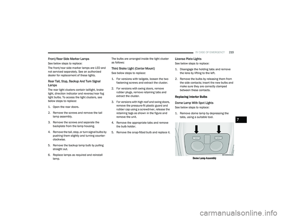
1. Remove dome lamp by depressing the tabs, using a suitable tool.
Dome Lamp Assembly
7
21_VM_OM_EN_USC_t.book Page 215
Page 219 of 280

217
SERVICING AND MAINTENANCE
SCHEDULED SERVICING
Your vehicle is equipped with an automatic oil
change indicator system. The oil change
indicator system will remind you that it is time to
take your vehicle in for scheduled maintenance.
Based on engine operation conditions, the oil
change indicator message will illuminate. This
means that service is required for your vehicle.
Operating conditions such as frequent
short-trips, trailer tow, extended engine idle
time, extremely hot or cold ambient
temperatures will influence when the “Oil
Change Required” message is displayed.
Severe Operating Conditions can cause the
change oil message to illuminate as early as
3,500 miles (5,600 km) since last reset. Have
your vehicle serviced as soon as possible,
within the next 500 miles (805 km).
An authorized dealer will reset the oil change
indicator message after completing the
scheduled oil change. If a scheduled oil change
is performed by someone other than an
authorized dealer, to reset the message
Úpage 46. NOTE:
Under no circumstances should oil change
intervals exceed 10,000 miles (16,000 km),
350 hours of engine run time or 12 months,
whichever comes first. The 350 hours of engine
run or idle time is generally only a concern for
fleet customers.
Severe Duty All Models
Vehicles that are operated in a dusty and
off-road environment, or predominately at idle
or very low engine RPM are known as Severe
Duty vehicles. It is recommended that you
change Engine Oil at 4,000 miles (6,500 km) or
350 hours of engine run time.
Once A Month Or Before A Long Trip:
Check engine oil level.
Check windshield washer fluid level.
Check tire pressure and look for unusual
wear or damage. Rotate tires at the first sign
of irregular wear, even if it occurs before the
oil indicator system turns on.
Check the fluid levels of the coolant reservoir
and brake master cylinder, fill as needed.
Check function of all interior and exterior
lights.
Maintenance Plan
Refer to the maintenance schedule for the
required maintenance intervals. More frequent
maintenance may be needed in severe
conditions, such as dusty areas and very short
trip driving. In some extreme conditions,
additional maintenance not specified in the
maintenance schedule may be required.
8
21_VM_OM_EN_USC_t.book Page 217