2021 RAM PROMASTER CITY engine
[x] Cancel search: enginePage 30 of 280

28GETTING TO KNOW YOUR VEHICLE
High/Low Beam Switch
Pull the multifunction lever toward the steering
wheel to switch the headlights to high beams.
Pull the multifunction lever again to turn the low
beams back on.
Flash-To-Pass
You can signal another vehicle with your
headlights by lightly pulling the multifunction
lever toward you. This will cause the high beam
headlights to turn on, and remain on, until the
lever is released.
Parking Lights
These lights can only be turned on with the
ignition in the STOP (OFF/LOCK) position or
removed. Move the end of the multifunction
lever to O (Off) position, and then to the
headlight position.
The indicator light telltale in the instrument
panel comes on. The lights stay on until the next
ignition cycle is performed.
Follow Me Home/Headlight Delay
When this feature is selected, the driver can
choose to have the headlights remain on for a
preset period of time after the engine is turned
off.
Activation
Remove the key or turn the ignition to the STOP
(OFF/LOCK) position, and pull the multifunction
lever toward the steering wheel within two
minutes. Each time the lever is pulled, the
activation of the lights will be extended by
30 seconds. The activation of the lights can be
extended to a maximum of 210 seconds.
Deactivation
Pull the multifunction lever toward the steering
wheel and hold it for more than two seconds.
Fog Lights — If Equipped
The fog light switch is located on the center
stack of the instrument panel, just above the
climate controls. Push the switch once to turn the fog
lights on. Push the switch a second
time to turn the fog lights off.
NOTE:
If the vehicle’s ignition is turned off, the fog
lights will also turn off.
Turn Signals
Move the multifunction lever up or down to
activate the turn signals. The arrows on each
side of the instrument cluster flash to show
proper operation.
NOTE:
If either light remains on and does not flash, or
there is a very fast flash rate, check for a defec -
tive outside light bulb.
Lane Change Assist
Lightly push the multifunction lever up or down,
without moving beyond the detent, and the turn
signal will flash five times then automatically
turn off.
21_VM_OM_EN_USC_t.book Page 28
Page 32 of 280
30GETTING TO KNOW YOUR VEHICLE
WIPERS AND WASHERS
The windshield wiper/washer lever is located on
the right side of the steering column.
NOTE:
The windshield wipers/washers will only
operate with the ignition in the MAR (ACC/ON/
RUN) position.
Front Wiper Operation
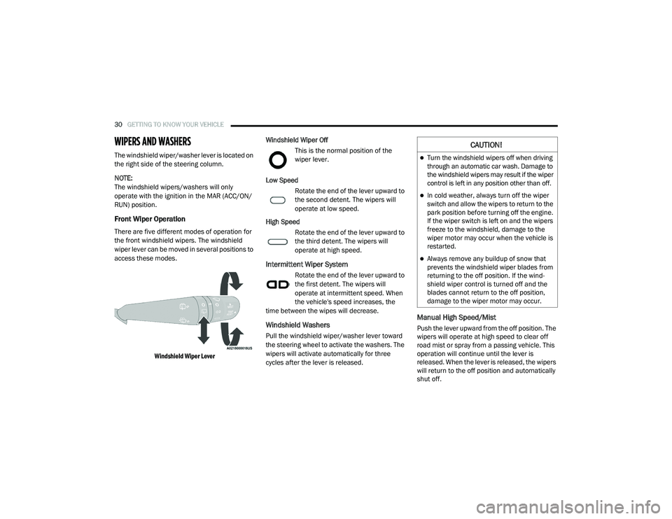
There are five different modes of operation for
the front windshield wipers. The windshield
wiper lever can be moved in several positions to
access these modes.
Windshield Wiper Lever
Windshield Wiper Off
This is the normal position of the
wiper lever.
Low Speed Rotate the end of the lever upward to
the second detent. The wipers will
operate at low speed.
High Speed Rotate the end of the lever upward to
the third detent. The wipers will
operate at high speed.
Intermittent Wiper System
Rotate the end of the lever upward to
the first detent. The wipers will
operate at intermittent speed. When
the vehicle's speed increases, the
time between the wipes will decrease.
Windshield Washers
Pull the windshield wiper/washer lever toward
the steering wheel to activate the washers. The
wipers will activate automatically for three
cycles after the lever is released.
Manual High Speed/Mist
Push the lever upward from the off position. The
wipers will operate at high speed to clear off
road mist or spray from a passing vehicle. This
operation will continue until the lever is
released. When the lever is released, the wipers
will return to the off position and automatically
shut off.
CAUTION!
Turn the windshield wipers off when driving
through an automatic car wash. Damage to
the windshield wipers may result if the wiper
control is left in any position other than off.
In cold weather, always turn off the wiper
switch and allow the wipers to return to the
park position before turning off the engine.
If the wiper switch is left on and the wipers
freeze to the windshield, damage to the
wiper motor may occur when the vehicle is
restarted.
Always remove any buildup of snow that
prevents the windshield wiper blades from
returning to the off position. If the wind -
shield wiper control is turned off and the
blades cannot return to the off position,
damage to the wiper motor may occur.
21_VM_OM_EN_USC_t.book Page 30
Page 35 of 280
GETTING TO KNOW YOUR VEHICLE33
Bi-Level Mode
Air comes from the instrument panel
outlets and floor outlets. A slight
amount of air is directed through the
defrost and side window demister
outlets.
NOTE:
Bi-Level mode is designed under comfort condi -
tions to provide cooler air out of the panel
outlets and warmer air from the floor outlets.
Floor Mode
Air comes from the floor outlets. A
slight amount of air is directed
through the defrost and side window
demister outlets.
Mix Mode
Air is directed through the floor,
defrost, and side window demister
outlets. This setting works best in cold
or snowy conditions that require extra
heat to the windshield. This setting is good for
maintaining comfort while reducing moisture on
the windshield.
Operating Tips
NOTE:
Refer to the chart at the end of this section for
suggested control settings for various weather
conditions.
Summer Operation
The engine cooling system must be protected
with a high-quality antifreeze coolant to provide
proper corrosion protection and to protect
against engine overheating. OAT coolant
(conforming to MS.90032) is recommended
Ú page 259.
Winter Operation
To ensure the best possible heater and
defroster performance, make sure the engine
cooling system is functioning properly and the
proper amount, type, and concentration of
coolant is used Ú page 259. Use of the Air
Recirculation mode during Winter months is not
recommended because it may cause window
fogging.
Vacation/Storage
Any time you store your vehicle or keep it out of
service (i.e., vacation) for two weeks or more,
run the air conditioning system at idle for about
five minutes in fresh air with the blower setting
on high. This will ensure adequate system
lubrication to minimize the possibility of
compressor damage when the system is started
again.
Window Fogging
Vehicle windows tend to fog on the inside of the
glass in mild, rainy and/or humid weather. To
clear the windows, select Defrost or Mix mode
and increase the front blower speed. Do not use
the Recirculation mode without A/C for long
periods, as fogging may occur.
2
21_VM_OM_EN_USC_t.book Page 33
Page 43 of 280
GETTING TO KNOW YOUR VEHICLE41
(Continued)
(Continued)
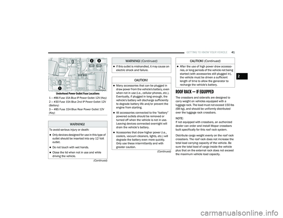
Underhood Power Outlet Fuse Locations
ROOF RACK — IF EQUIPPED
The crossbars and siderails are designed to
carry weight on vehicles equipped with a
luggage rack. The load must not exceed 150 lbs
(68 kg), and should be uniformly distributed
over the luggage rack crossbars.
NOTE:
If not equipped with crossbars, an authorized
dealer can order and install Mopar crossbars
built specifically for this roof rack system.
Distribute cargo weight evenly on the roof rack
crossbars. The roof rack does not increase the
total load carrying capacity of the vehicle. Be
sure the total load of cargo inside the vehicle
plus that on the external rack does not exceed
the maximum vehicle load capacity.1 — #86 Fuse 15A Blue IP Power Outlet 12V (Key)
2 — #30 Fuse 15A Blue 2nd IP Power Outlet 12V
(Battery)
3 — #85 Fuse 15A Blue Rear Power Outlet 12V
(Key)
WARNING!
To avoid serious injury or death:
Only devices designed for use in this type of
outlet should be inserted into any 12 Volt
outlet.
Do not touch with wet hands.
Close the lid when not in use and while
driving the vehicle.
If this outlet is mishandled, it may cause an
electric shock and failure.
CAUTION!
Many accessories that can be plugged in
draw power from the vehicle's battery, even
when not in use (i.e., cellular phones, etc.).
Eventually, if plugged in long enough, the
vehicle's battery will discharge sufficiently
to degrade battery life and/or prevent the
engine from starting.
All accessories connected to the “battery”
powered outlets should be removed or
turned off when the vehicle is not in use.
Leaving devices connected overnight will
drain the vehicle’s battery.
Accessories that draw higher power (i.e.,
coolers, vacuum cleaners, lights, etc.) will
degrade the battery even more quickly.
Only use these intermittently and with
greater caution.
WARNING! (Continued)
After the use of high power draw accesso -
ries, or long periods of the vehicle not being
started (with accessories still plugged in),
the vehicle must be driven a sufficient
length of time to allow the generator to
recharge the vehicle's battery.
CAUTION! (Continued)
2
21_VM_OM_EN_USC_t.book Page 41
Page 46 of 280
44GETTING TO KNOW YOUR INSTRUMENT PANEL
Instrument Cluster Descriptions
1. Speedometer
Indicates vehicle speed.
2. Fuel Gauge
The pointer shows the level of fuel in the
fuel tank when the ignition switch is in
the ON/RUN position.
The fuel pump arrow symbol points
to the side of the vehicle where the
fuel door is located.
3. Temperature Gauge
The temperature gauge shows engine
coolant temperature. Any reading within
the normal range indicates that the
engine cooling system is operating satis -
factorily.
The pointer will likely indicate a higher
temperature when driving in hot weather
or up mountain grades. It should not be
allowed to exceed the upper limits of the
normal operating range. 4. Tachometer
Indicates the engine speed in revolutions
per minute (RPM x 1000).
5. Instrument Cluster Display
When the appropriate conditions exist,
this display shows the instrument cluster
display messages Ú page 44.
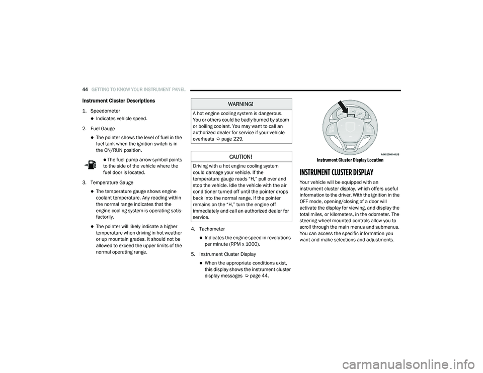
Instrument Cluster Display Location
INSTRUMENT CLUSTER DISPLAY
Your vehicle will be equipped with an
instrument cluster display, which offers useful
information to the driver. With the ignition in the
OFF mode, opening/closing of a door will
activate the display for viewing, and display the
total miles, or kilometers, in the odometer. The
steering wheel mounted controls allow you to
scroll through the main menus and submenus.
You can access the specific information you
want and make selections and adjustments.
WARNING!
A hot engine cooling system is dangerous.
You or others could be badly burned by steam
or boiling coolant. You may want to call an
authorized dealer for service if your vehicle
overheats Ú
page 229.
CAUTION!
Driving with a hot engine cooling system
could damage your vehicle. If the
temperature gauge reads “H,” pull over and
stop the vehicle. Idle the vehicle with the air
conditioner turned off until the pointer drops
back into the normal range. If the pointer
remains on the “H,” turn the engine off
immediately and call an authorized dealer for
service.
21_VM_OM_EN_USC_t.book Page 44
Page 48 of 280
46GETTING TO KNOW YOUR INSTRUMENT PANEL
3. Briefly push and release the MENU button
to select the displayed submenu option and
to open the relevant setup menu.
4. Push and release the up or down
arrow button (by single pushes) to select the
new setting for this submenu option.
5. Briefly push and release the MENU button
to store the new setting and go back to the
previously selected submenu option.
6. Push and hold the MENU button to return to
the main menu (short hold) or the main
screen (longer hold).
Change Engine Oil — If Equipped
Your vehicle may be equipped with an engine oil
change indicator system. The “Change Engine
Oil” message will display in the instrument
cluster display. The engine oil change indicator
system is duty cycle based, which means the
engine oil change interval may fluctuate,
dependent upon your personal driving style. Unless reset, this message will continue to
display each time you turn the ignition switch to
the ON/RUN position. To turn off the message
temporarily, push and release the
MENU
button. To reset the oil change indicator system
(after performing the scheduled maintenance),
refer to the following procedure.
1. Turn the ignition switch to the ON position (do not start the engine).
2. Fully push the accelerator pedal slowly, three times, within 10 seconds.
3. Turn the ignition switch to the OFF/LOCK position.
NOTE:
If the indicator message illuminates when you
start the vehicle, the oil change indicator
system did not reset. If necessary, repeat this
procedure.
Instrument Cluster Display Menu Items
Speed Beep
This function is used to set a speed limit (MPH
or km/h); the driver is alerted when this limit is
exceeded.
To set the desired speed limit:
1. Push the
MENU
button briefly. The display
will show the wording (SPEED BEEP) and
the unit (MPH) or (km/h) previously set.
2. If the function is on, push and release the up or down arrow button to select the
required speed limit and then push MENU
to confirm.
NOTE:
The speed may be set in the range from 20 to
125 mph (30 to 200 km/h) according to the previously chosen unit.
The setting will increase/decrease by five units
each time the up or down arrow button is
pushed. Hold down the up or down arrow
button to automatically increase/decrease the
setting rapidly. Complete the adjustment when
you approach the desired value.
21_VM_OM_EN_USC_t.book Page 46
Page 51 of 280

GETTING TO KNOW YOUR INSTRUMENT PANEL49
Values Displayed
Range
This indicates the distance which may be
traveled with the fuel remaining in the tank,
assuming that driving conditions will not
change. The message “----” will appear on the
display in the following cases:
Distance less than 30 miles (or 50 km).
The vehicle is parked for a long time with the
engine running.
NOTE:
The range depends on several factors: driving
style, type of route (freeway, residential, moun -
tain roads, etc.), conditions of use of the vehicle
(load, tire pressure, etc.). Trip planning must
take into account the above notes.
Travel Distance
This value shows the distance covered since the
last reset.
Average Fuel Consumption
This value shows the approximate average
consumption since the last reset.
Current Fuel Consumption
This indicates the fuel consumption. The value
is constantly updated. The message “----” will
appear on the display if the vehicle is parked
with the engine running.
Average Speed
This value shows the vehicle's average speed as
a function of the overall time elapsed since the
last reset.
Travel Time
This value shows the time elapsed since the last
reset.
WARNING LIGHTS AND MESSAGES
The warning/indicator lights will illuminate in
the instrument panel together with a dedicated
message and/or acoustic signal when
applicable. These indications are indicative and
precautionary and as such must not be
considered as exhaustive and/or alternative to
the information contained in the Owner’s
Manual, which you are advised to read carefully
in all cases. Always refer to the information in
this chapter in the event of a failure indication.
All active telltales will display first if applicable.
The system check menu may appear different based upon equipment options and current
vehicle status. Some telltales are optional and
may not appear.
Red Warning Lights
Air Bag Warning Light
This light will turn on for four to eight
seconds as a bulb check when the
ignition is placed in the ON/RUN or
MAR/ON/RUN position. If the light is
either not on during startup, stays on, or turns
on while driving, have the system inspected by
an authorized dealer as soon as possible. This
light will illuminate with a single chime when a
fault with the Air Bag Warning Light has been
detected, it will stay on until the fault is cleared.
If the light comes on intermittently or remains
on while driving, have an authorized dealer
service the vehicle immediately.
Brake Warning Light
This warning light monitors various
brake functions, including brake fluid
level and parking brake application. If
the brake light turns on it may
indicate that the parking brake is applied, that
the brake fluid level is low, or that there is a
problem with the Anti-Lock Brake System
reservoir.
3
21_VM_OM_EN_USC_t.book Page 49
Page 52 of 280

50GETTING TO KNOW YOUR INSTRUMENT PANEL
If the light remains on when the parking brake
has been disengaged, and the fluid level is at
the full mark on the master cylinder reservoir, it
indicates a possible brake hydraulic system
malfunction or that a problem with the Brake
Booster has been detected by the Anti-Lock
Brake System (ABS) / Electronic Stability
Control (ESC) system. In this case, the light will
remain on until the condition has been
corrected. If the problem is related to the brake
booster, the ABS pump will run when applying
the brake, and a brake pedal pulsation may be
felt during each stop.
The dual brake system provides a reserve
braking capacity in the event of a failure to a
portion of the hydraulic system. A leak in either
half of the dual brake system is indicated by the
Brake Warning Light, which will turn on when
the brake fluid level in the master cylinder has
dropped below a specified level.
The light will remain on until the cause is
corrected. NOTE:
The light may flash momentarily during sharp
cornering maneuvers, which change fluid level
conditions. The vehicle should have service
performed, and the brake fluid level checked.
If brake failure is indicated, immediate repair is
necessary.
Vehicles equipped with the Anti-Lock Brake
System (ABS) are also equipped with Electronic
Brake Force Distribution (EBD). In the event of
an EBD failure, the Brake Warning Light will turn
on along with the ABS Light. Immediate repair to
the ABS system is required.
Operation of the Brake Warning Light can be
checked by turning the ignition switch from the
OFF position to the ON/RUN position. The light
should illuminate for approximately two seconds. The light should then turn off unless
the parking brake is applied or a brake fault is
detected. If the light does not illuminate, have
the light inspected by an authorized dealer.
The light also will turn on when the parking
brake is applied with the ignition switch in the
ON/RUN position.
NOTE:
This light shows only that the parking brake is
applied. It does not show the degree of brake
application.
Battery Charge Warning Light
This warning light will illuminate when
the battery is not charging properly. If
it stays on while the engine is running,
there may be a malfunction with the
charging system. Contact an authorized dealer
as soon as possible. This indicates a possible
problem with the electrical system or a related
component.
WARNING!
Driving a vehicle with the red brake light on is
dangerous. Part of the brake system may
have failed. It will take longer to stop the
vehicle. You could have a collision. Have the
vehicle checked immediately.
21_VM_OM_EN_USC_t.book Page 50