2021 RAM PROMASTER CITY ABS
[x] Cancel search: ABSPage 6 of 280

4
MULTIMEDIA
UCONNECT SYSTEMS ..........................................86
CYBERSECURITY ..................................................86
UCONNECT SETTINGS .........................................87 Uconnect 3/3 NAV Settings ........................ 87
UCONNECT INTRODUCTION.................................97
Identifying Your Radio ................................. 97
Safety And General Information ................. 99
UCONNECT MODES ........................................... 100
Radio Mode ................................................100
Media Mode ...............................................107Phone Mode ..............................................109
NAVIGATION MODE — IF EQUIPPED ................ 121
Operating Navigation Mode —
If Equipped .................................................121
STEERING WHEEL AUDIO CONTROLS — IF
EQUIPPED ........................................................... 142
Radio Operation .........................................142
Media Mode ...............................................142
RAM TELEMATICS - IF EQUIPPED .................... 142
Ram Telematics General Information ......143
RADIO OPERATION AND MOBILE PHONES.... 143
Regulatory And Safety Information........... 144
SAFETY
SAFETY FEATURES ............................................ 145 Four-Wheel Anti-Lock Brake
System (ABS) ..............................................145 Electronic Brake Control (EBC) System ...146 AUXILIARY DRIVING SYSTEMS.........................149
Tire Pressure Monitoring
System (TPMS) ........................................... 149
OCCUPANT RESTRAINT SYSTEMS .................. 153
Occupant Restraint Systems .................... 153
Important Safety Precautions ................... 153
Seat Belt Systems ..................................... 154
Supplemental Restraint Systems (SRS)... 161
Child Restraints ......................................... 170
Transporting Pets ...................................... 184
SAFETY TIPS ....................................................... 185
Transporting Passengers .......................... 185Exhaust Gas .............................................. 185
Safety Checks You Should Make Inside
The Vehicle ................................................ 185 Periodic Safety Checks You Should Make
Outside The Vehicle ................................... 187
IN CASE OF EMERGENCY
HAZARD WARNING FLASHERS........................188
FUSES ..................................................................188
General Information .................................. 188Underhood Fuses ...................................... 189
Interior Fuses ............................................. 192
Central Unit Fuse Panel............................. 193 JACKING AND TIRE CHANGING ...................... 194
Jack Location — If Equipped ..................... 194
Removing The Spare Tire — If Equipped .. 194Preparations For Jacking ......................... 196
Jacking Instructions................................... 197
Vehicles With Alloy Wheels ....................... 200Vehicles Equipped With Wheel Covers .... 201
TIRE SERVICE KIT — IF EQUIPPED .................. 202
Tire Service Kit Storage............................. 202
Tire Service Kit Usage ............................... 202
JUMP STARTING ................................................ 204
Preparations For Jump Starting ................ 205
Jump Starting Procedure .......................... 206
IF YOUR ENGINE OVERHEATS ......................... 207
IGNITION KEY REMOVAL OVERRIDE ............... 208
GEAR SELECTOR OVERRIDE ............................ 209
FREEING A STUCK VEHICLE ............................ 209
TOWING A DISABLED VEHICLE ........................ 211
ENHANCED ACCIDENT RESPONSE SYSTEM
(EARS) ................................................................ 212
EVENT DATA RECORDER (EDR) ....................... 212
BULB REPLACEMENT ........................................ 213 Replacement Bulbs ................................... 213
Replacing Exterior Bulbs ........................... 214
Replacing Interior Bulbs ............................ 215
21_VM_OM_EN_USC_t.book Page 4
Page 11 of 280

9
Yellow Warning Lights
Anti-Lock Brake System (ABS) Warning Light Úpage 52
Low Fuel Warning Light Úpage 52
Generic Warning Light Úpage 52
Tire Pressure Monitoring System (TPMS) Warning Light Ú page 53
Vehicle Security Warning Light Úpage 54
Engine Check/Malfunction Indicator Warning Light (MIL)
Ú page 54
Electronic Stability Control (ESC) Warning Light — If Equipped Ú page 55
Electronic Stability Control (ESC) OFF Warning Light — If Equipped Úpage 55
Green Indicator Lights
Turn Signal Indicator Lights
Úpage 55
Park/Headlight On Indicator Light Úpage 55
Front Fog Indicator Light — If Equipped Úpage 55
Cruise Control Indicator Light — If Equipped Úpage 55
Blue Indicator Lights
High Beam Indicator Light
Úpage 56
1
21_VM_OM_EN_USC_t.book Page 9
Page 52 of 280

50GETTING TO KNOW YOUR INSTRUMENT PANEL
If the light remains on when the parking brake
has been disengaged, and the fluid level is at
the full mark on the master cylinder reservoir, it
indicates a possible brake hydraulic system
malfunction or that a problem with the Brake
Booster has been detected by the Anti-Lock
Brake System (ABS) / Electronic Stability
Control (ESC) system. In this case, the light will
remain on until the condition has been
corrected. If the problem is related to the brake
booster, the ABS pump will run when applying
the brake, and a brake pedal pulsation may be
felt during each stop.
The dual brake system provides a reserve
braking capacity in the event of a failure to a
portion of the hydraulic system. A leak in either
half of the dual brake system is indicated by the
Brake Warning Light, which will turn on when
the brake fluid level in the master cylinder has
dropped below a specified level.
The light will remain on until the cause is
corrected. NOTE:
The light may flash momentarily during sharp
cornering maneuvers, which change fluid level
conditions. The vehicle should have service
performed, and the brake fluid level checked.
If brake failure is indicated, immediate repair is
necessary.
Vehicles equipped with the Anti-Lock Brake
System (ABS) are also equipped with Electronic
Brake Force Distribution (EBD). In the event of
an EBD failure, the Brake Warning Light will turn
on along with the ABS Light. Immediate repair to
the ABS system is required.
Operation of the Brake Warning Light can be
checked by turning the ignition switch from the
OFF position to the ON/RUN position. The light
should illuminate for approximately two seconds. The light should then turn off unless
the parking brake is applied or a brake fault is
detected. If the light does not illuminate, have
the light inspected by an authorized dealer.
The light also will turn on when the parking
brake is applied with the ignition switch in the
ON/RUN position.
NOTE:
This light shows only that the parking brake is
applied. It does not show the degree of brake
application.
Battery Charge Warning Light
This warning light will illuminate when
the battery is not charging properly. If
it stays on while the engine is running,
there may be a malfunction with the
charging system. Contact an authorized dealer
as soon as possible. This indicates a possible
problem with the electrical system or a related
component.
WARNING!
Driving a vehicle with the red brake light on is
dangerous. Part of the brake system may
have failed. It will take longer to stop the
vehicle. You could have a collision. Have the
vehicle checked immediately.
21_VM_OM_EN_USC_t.book Page 50
Page 54 of 280

52GETTING TO KNOW YOUR INSTRUMENT PANEL
Seat Belt Reminder Warning Light
When the ignition is first placed in the
ON/RUN or MAR/ON/RUN position, if
the driver’s seat belt is unbuckled, a
chime will sound and the light will turn
on. When driving, if the driver or front passenger
seat belt remains unbuckled, the Seat Belt
Reminder Light will flash or remain on
continuously and a chime will sound
Ú page 153.
Transmission Fault Warning Light
This light will illuminate (together with
a message in the instrument cluster
display and a buzzer) to indicate a
transmission fault. Contact an
authorized dealer if the message remains after
restarting the engine.
Engine Oil Level Warning Light
This warning light appears on the
panel when the engine oil level falls
below the minimum recommended
value. Restore the correct engine oil
level or contact your authorized dealer for
service.
Yellow Warning Lights
Anti-Lock Brake System (ABS) Warning Light
This light monitors the ABS. The light
will turn on when the ignition is placed
in the ON/RUN or MAR/ON/RUN
position and may stay on for as long
as four seconds.
If the ABS light remains on or turns on while
driving, then the Anti-Lock portion of the brake
system is not functioning and service is
required. However, the conventional brake system will continue to operate normally if the
brake warning light is not on.
If the ABS light is on, the brake system should
be serviced as soon as possible to restore the
benefits of Anti-Lock Brakes. If the ABS light
does not turn on when the ignition is placed in
the ON/RUN or MAR/ON/RUN position, have
the light inspected by an authorized dealer.
Low Fuel Warning Light
When the fuel level reaches
approximately 2–3 gal (9–11 L) this
light will turn on, and remain on until
fuel is added.
Generic Warning Light
The Generic Warning Light will
illuminate if any of the following
conditions occur: Engine Oil Pressure
Sensor Failure, External Light Failure,
Parking Sensor Failure, Fuel Cut-Off Fail/
Intervention, Generic Failure on Trailer, or Air
Bag telltale recovery.
The telltale will blink in case of an Air Bag
Warning Light Failure. Contact an authorized
dealer immediately for service.
WARNING!
If you continue operating the vehicle when
the Transmission Temperature Warning Light
is illuminated you could cause the fluid to boil
over, come in contact with hot engine or
exhaust components and cause a fire.
CAUTION!
Continuous driving with the Transmission
Temperature Warning Light illuminated will
eventually cause severe transmission
damage or transmission failure.
21_VM_OM_EN_USC_t.book Page 52
Page 106 of 280

104MULTIMEDIA
Favorites
Press the Favorites button on the touchscreen
to activate the favorites menu, which will time
out within 20 seconds in absence of user
interaction.
You can exit the Favorites Menu by a press of
the X button.
The favorites feature enables you to set a
favorite artist or song that is currently playing.
The radio then uses this information to alert you
when either the favorite artist or song is being
played at any time by any of the SiriusXM®
Channels.
The maximum number of favorites that can be
stored in the Radio is 50.
Favorite Artist: While the song is playing, to set
a favorite artist, press the Favorites button on
the touchscreen and then the Favorite Artist
button on the touchscreen.
Favorite Song: While the song is playing, to set
a favorite song, press the Favorites button on
the touchscreen and then the Favorite Song
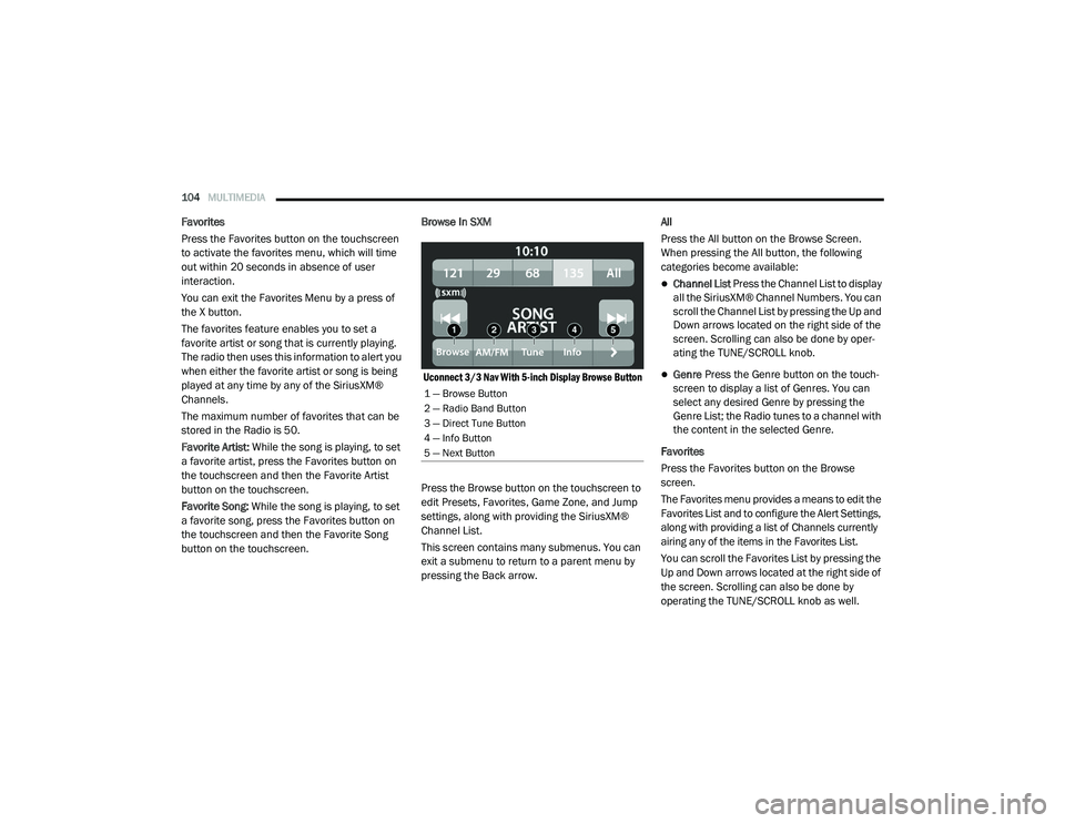
button on the touchscreen. Browse In SXM
Uconnect 3/3 Nav With 5-inch Display Browse Button
Press the Browse button on the touchscreen to
edit Presets, Favorites, Game Zone, and Jump
settings, along with providing the SiriusXM®
Channel List.
This screen contains many submenus. You can
exit a submenu to return to a parent menu by
pressing the Back arrow. All
Press the All button on the Browse Screen.
When pressing the All button, the following
categories become available:
Channel List Press the Channel List to display
all the SiriusXM® Channel Numbers. You can
scroll the Channel List by pressing the Up and
Down arrows located on the right side of the
screen. Scrolling can also be done by oper
-
ating the TUNE/SCROLL knob.
Genre Press the Genre button on the touch -
screen to display a list of Genres. You can
select any desired Genre by pressing the
Genre List; the Radio tunes to a channel with
the content in the selected Genre.
Favorites
Press the Favorites button on the Browse
screen.
The Favorites menu provides a means to edit the
Favorites List and to configure the Alert Settings,
along with providing a list of Channels currently
airing any of the items in the Favorites List.
You can scroll the Favorites List by pressing the
Up and Down arrows located at the right side of
the screen. Scrolling can also be done by
operating the TUNE/SCROLL knob as well.
1 — Browse Button
2 — Radio Band Button
3 — Direct Tune Button
4 — Info Button
5 — Next Button
21_VM_OM_EN_USC_t.book Page 104
Page 147 of 280

145
(Continued)
SAFETY
SAFETY FEATURES
Four-Wheel Anti-Lock Brake System (ABS)
ABS is designed to aid the driver in maintaining
vehicle control under adverse braking
conditions. The system operates with a
separate computer to modulate hydraulic
pressure, to prevent wheel lock-up and to help
avoid skidding on slippery surfaces.
The system's pump motor runs during an ABS
stop to provide regulated hydraulic pressure.
The pump motor makes a low humming noise
during operation, which is normal.
The ABS includes an amber ABS Warning Light.
When the light is illuminated, the ABS is not
functioning. The system reverts to standard
non-anti-lock brakes. Turning the ignition OFF
and ON again may reset the ABS if the fault
detected was only momentary.When you are in a severe braking condition
involving the use of the ABS, you will experience
some pedal drop as the vehicle comes to a stop.
This is the result of the system reverting to the
base brake system.
Engagement of the ABS may be accompanied
by a pulsing sensation. You may also hear a
clicking noise. These occurrences are normal
and indicate that the system is functioning
properly.
WARNING!
The ABS contains sophisticated electronic
equipment that may be susceptible to inter
-
ference caused by improperly installed or
high output radio transmitting equipment.
This interference can cause possible loss of
anti-lock braking capability. Installation of
such equipment should be performed by
qualified professionals.
Pumping of the Anti-Lock Brakes will
diminish their effectiveness and may lead
to a collision. Pumping makes the stopping
distance longer. Just press firmly on your
brake pedal when you need to slow down or
stop.
The ABS cannot prevent the natural laws of
physics from acting on the vehicle, nor can
it increase braking or steering efficiency
beyond that afforded by the condition of the
vehicle brakes and tires or the traction
afforded.
The ABS cannot prevent collisions,
including those resulting from excessive
speed in turns, following another vehicle
too closely, or hydroplaning.
The capabilities of an ABS equipped vehicle
must never be exploited in a reckless or
dangerous manner that could jeopardize
the user’s safety or the safety of others.
WARNING! (Continued)
6
21_VM_OM_EN_USC_t.book Page 145
Page 148 of 280

146SAFETY
Electronic Brake Control (EBC) System
Your vehicle is equipped with an advanced
Electronic Brake Control (EBC) system that
includes the Brake Assist System (BAS),
Traction Control System (TCS), Hill Start Assist
(HSA), Electronic Stability Control (ESC),
Electronic Roll Mitigation (ERM) and Trailer
Sway Control (TSC). All systems work together to
enhance vehicle stability and control in various
driving conditions and are commonly referred to
as ESC.
Brake Assist System (BAS)
BAS is designed to optimize the vehicle’s
braking capability during emergency braking
maneuvers. The system detects an emergency
braking situation by sensing the rate and
amount of brake application and then applies
optimum pressure to the brakes. This can help
reduce braking distances. The BAS
complements the Anti-Lock Brake System
(ABS). Applying the brakes very quickly results
in the best BAS assistance. To receive the
benefit of the system, you must apply continuous braking pressure during the
stopping sequence (do not “pump” the brakes).
Do not reduce brake pedal pressure unless
braking is no longer desired. Once the brake
pedal is released, the BAS is deactivated.
Electronic Stability Control (ESC)
ESC enhances directional control and stability
of the vehicle under various driving conditions.
ESC corrects for over/under steering of the
vehicle by applying the brake of the appropriate
wheel to counteract the above conditions.
Engine power may also be reduced to help the
vehicle maintain the desired path.
Oversteer - when the vehicle is turning more
than appropriate for the steering wheel posi
-
tion.
Understeer - when the vehicle is turning less
than appropriate for the steering wheel posi -
tion.
ESC uses sensors in the vehicle to determine
the vehicle path intended by the driver and
compares it to the actual path of the vehicle.
When the actual path does not match the
intended path, ESC applies the brake of the
appropriate wheel to assist in counteracting the
oversteer or understeer condition.
WARNING!
The Brake Assist System (BAS) cannot
prevent the natural laws of physics from
acting on the vehicle, nor can it increase the
traction afforded by prevailing road
conditions. BAS cannot prevent collisions,
including those resulting from excessive
speed in turns, driving on very slippery
surfaces, or hydroplaning. The capabilities of
a BAS-equipped vehicle must never be
exploited in a reckless or dangerous manner,
which could jeopardize the user's safety or
the safety of others.
21_VM_OM_EN_USC_t.book Page 146
Page 166 of 280

164SAFETY
The steering wheel hub trim cover and the
upper passenger side of the instrument panel
separate and fold out of the way as the air bags
inflate to their full size. The front air bags fully
inflate in less time than it takes to blink your
eyes. The front air bags then quickly deflate
while helping to restrain the driver and front
passenger.
Knee Impact Bolsters
The Knee Impact Bolsters help protect the
knees of the driver and front passenger, and
position the front occupants for improved
interaction with the front air bags.
Supplemental Driver Knee Air Bag
This vehicle is equipped with a Supplemental
Driver Knee Air Bag mounted in the instrument
panel below the steering column. The
Supplemental Driver Knee Air Bag provides enhanced protection during a frontal impact by
working together with the seat belts,
pretensioners, and front air bags.
Supplemental Side Air Bags
Supplemental Seat-Mounted Side Air Bags
(SABs)
This vehicle is equipped with Supplemental
Seat-Mounted Side Air Bags (SABs).
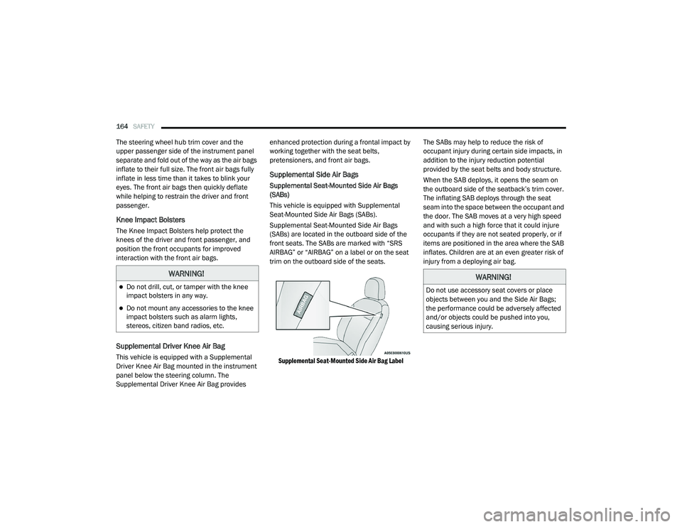
Supplemental Seat-Mounted Side Air Bags
(SABs) are located in the outboard side of the
front seats. The SABs are marked with “SRS
AIRBAG” or “AIRBAG” on a label or on the seat
trim on the outboard side of the seats.
Supplemental Seat-Mounted Side Air Bag Label
The SABs may help to reduce the risk of
occupant injury during certain side impacts, in
addition to the injury reduction potential
provided by the seat belts and body structure.
When the SAB deploys, it opens the seam on
the outboard side of the seatback’s trim cover.
The inflating SAB deploys through the seat
seam into the space between the occupant and
the door. The SAB moves at a very high speed
and with such a high force that it could injure
occupants if they are not seated properly, or if
items are positioned in the area where the SAB
inflates. Children are at an even greater risk of
injury from a deploying air bag.
WARNING!
Do not drill, cut, or tamper with the knee
impact bolsters in any way.
Do not mount any accessories to the knee
impact bolsters such as alarm lights,
stereos, citizen band radios, etc.
WARNING!
Do not use accessory seat covers or place
objects between you and the Side Air Bags;
the performance could be adversely affected
and/or objects could be pushed into you,
causing serious injury.
21_VM_OM_EN_USC_t.book Page 164