2021 RAM PROMASTER CITY ABS
[x] Cancel search: ABSPage 205 of 280

IN CASE OF EMERGENCY203
(Continued)
Insert the power plug into the vehicle power
outlet socket. Start the vehicle engine.
Push the Tire Service Kit power button on. The
electric compressor will be turned on, sealant
and air will inflate the tire.
Minimum 26 psi (1.8 bar) of pressure should be
reached within 20 minutes. If the pressure has
not been reached, turn off and remove the Tire
Service Kit, drive the vehicle 30 feet
(10 meters) back and forth, to better distribute
the sealant inside the tire.
Attach the clear flexible filling tube of the
compressor directly to the tire valve and repeat
the inflation process.
When the correct pressure has been reached,
start driving the vehicle to uniformly distribute
the sealant inside the tire. After 10 minutes,
stop and check the tire pressure. If the pressure
is below 19 psi (1.3 bar), do not drive the
vehicle, as the tire is too damaged, contact the
nearest authorized dealer.WARNING!
Do not attempt to seal a tire on the side of
the vehicle closest to traffic. Pull far enough
off the road to avoid the danger of being hit
when using the Tire Service Kit.
Do not use Tire Service Kit or drive the
vehicle under the following circumstances:
If the puncture in the tire tread is
approximately 1/4 inch (6 mm) or
larger.
If the tire has any sidewall damage.
If the tire has any damage from driving
with extremely low tire pressure.
If the tire has any damage from driving
on a flat tire.
If the wheel has any damage.
If you are unsure of the condition of the
tire or the wheel.
Keep Tire Service Kit away from open
flames or heat source.
A loose Tire Service Kit thrown forward in a
collision or hard stop could endanger the
occupants of the vehicle. Always stow the
Tire Service Kit in the place provided.
Failure to follow these warnings can result
in injuries that are serious or fatal to you,
your passengers, and others around you.
Take care not to allow the contents of Tire
Service Kit to come in contact with hair,
eyes, or clothing. Tire Service Kit sealant is
harmful if inhaled, swallowed, or absorbed
through the skin. It causes skin, eye, and
respiratory irritation. Flush immediately
with plenty of water if there is any contact
with eyes or skin. Change clothing as soon
as possible, if there is any contact with
clothing.
Tire Service Kit Sealant solution contains
latex. In case of an allergic reaction or rash,
consult a physician immediately. Keep Tire
Service Kit out of reach of children. If swal -
lowed, rinse mouth immediately with plenty
of water and drink plenty of water. Do not
induce vomiting! Consult a physician imme -
diately.
WARNING! (Continued)
7
21_VM_OM_EN_USC_t.book Page 203
Page 207 of 280

IN CASE OF EMERGENCY205
Preparations For Jump Starting
The battery in your vehicle is located in the front
of the engine compartment, behind the left
headlight assembly.
Battery Location
NOTE:
The positive battery post is covered with a
protective cap. Press on tabs, then lift up on the
cap to gain access to the positive battery post.
Positive Battery Post Protective Cap
Positive Battery Post Location
WARNING!
Take care to avoid the radiator cooling fan
whenever the hood is raised. It can start
anytime the ignition switch is ON. You can
be injured by moving fan blades.
Remove any metal jewelry such as rings,
watch bands and bracelets that could
make an inadvertent electrical contact. You
could be seriously injured.
Batteries contain sulfuric acid that can
burn your skin or eyes and generate
hydrogen gas which is flammable and
explosive. Keep open flames or sparks
away from the battery.
7
21_VM_OM_EN_USC_t.book Page 205
Page 217 of 280

IN CASE OF EMERGENCY215
Front/Rear Side Marker Lamps
See below steps to replace:
The front/rear side marker lamps are LED and
not serviced separately. See an authorized
dealer for replacement of these lights.
Rear Tail, Stop, Backup And Turn Signal
Lamps
The rear light clusters contain taillight, brake
light, direction indicator and reverse/rear fog
light bulbs. To access the light clusters, see
below steps to replace:
1. Open the rear doors.
2. Remove the screws and remove the tail
lamp assembly.
3. Remove the screws and separate the backplate from the lamp housing.
4. Remove the tail, stop, or turn signal bulbs by pushing them slightly and turning counter -
clockwise.
5. Remove the backup lamp bulb by pulling straight out.
6. Replace lamps as required and reinstall lamp. The bulbs are arranged inside the light cluster
as follows:
Third Brake Light (Center Mount)
See below steps to replace:
1. For versions with tailgate, loosen the two
fastening screws and extract the cluster.
2. For versions with swing doors, remove rubber plugs, remove retaining tabs and
extract the cluster.
3. For versions with high roof and swing doors, remove the pressure-fit plastic guard and
rubber cap using a screwdriver, release the
retaining tags as shown in the figure and
remove the unit.
4. Remove the appropriate tabs and remove the bulb holder.
5. Remove the snap-fitted bulb and replace it.
License Plate Lights
See below steps to replace:
1. Disengage the holding tabs and remove the lens by lifting to the left.
2. Remove the bulbs by releasing them from the side contacts; insert the new bulbs and
make sure they are correctly clamped
between these contacts.
Replacing Interior Bulbs
Dome Lamp With Spot Lights
See below steps to replace:
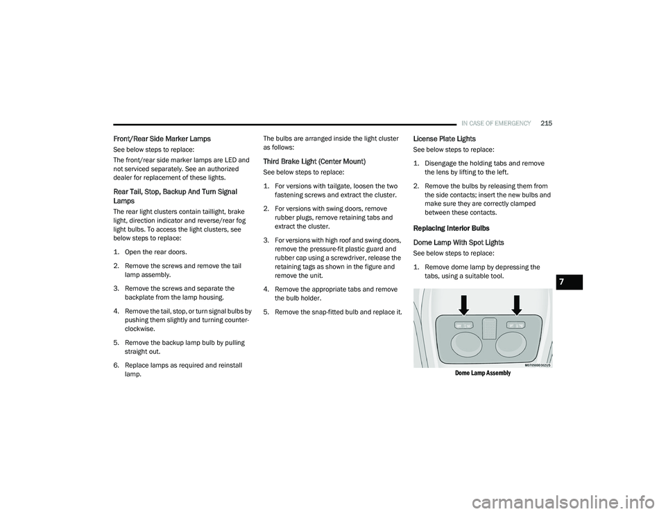
1. Remove dome lamp by depressing the tabs, using a suitable tool.
Dome Lamp Assembly
7
21_VM_OM_EN_USC_t.book Page 215
Page 218 of 280

216IN CASE OF EMERGENCY
2. Open protective cover.
Dome Lamp
3. Replace the bulbs releasing them from the side contacts making sure that the new
bulbs are correctly secured between the
contacts.
4. Close the protective cover and reposition it back into its housing, making sure that it
locks into place.
Rear Roof Lamp
See below steps to replace:
1. Remove roof lamp by depressing the tabs, using a suitable tool.
Roof Lamp
2. Open the cover.
Roof Lamp (Reverse Side)
3. Replace the bulb releasing them from the
side contacts making sure that the new
bulbs are correctly secured between the
contacts.
Roof Lamp (Reverse Side)
4. Close the protective cover and reposition it back into its housing, making sure that it
locks into place.
1 — Protective Cover
2 — Bulbs
1 — Cover
1 — Bulb
21_VM_OM_EN_USC_t.book Page 216
Page 233 of 280

SERVICING AND MAINTENANCE231
(Continued)
Brake Master Cylinder
The fluid in the master cylinder should be
checked when performing under hood services
or immediately if the “Brake Warning Light” is
illuminated.
Be sure to clean the top of the master cylinder
area before removing the cap. If necessary, add
fluid to bring the fluid level up to the
requirements described on the brake fluid
reservoir. With disc brakes, fluid level can be
expected to fall as the brake pads wear. Brake
fluid level should be checked when pads are
replaced. However, low fluid level may be
caused by a leak and a checkup may be
needed. Use only FCA recommended brake fluid
Ú page 261.
Automatic Transmission
Selection Of Lubricant
It is important to use the proper transmission
fluid to ensure optimum transmission
performance and life. Use only FCA specified
transmission fluid Ú page 261. It is important
to maintain the transmission fluid at the correct
level using the recommended fluid.
NOTE:
No chemical flushes should be used in any
transmission; only the approved lubricant
should be used.
WARNING!
Use only FCA recommended brake fluid
Ú page 261. Using the wrong type of brake
fluid can severely damage your brake
system and/or impair its performance. The
proper type of brake fluid for your vehicle is
also identified on the original factory
installed hydraulic master cylinder reser -
voir.
To avoid contamination from foreign matter
or moisture, use only new brake fluid or
fluid that has been in a tightly closed
container. Keep the master cylinder reser -
voir cap secured at all times. Brake fluid in
an open container absorbs moisture from
the air resulting in a lower boiling point. This
may cause it to boil unexpectedly during
hard or prolonged braking, resulting in
sudden brake failure. This could result in a
collision.
Overfilling the brake fluid reservoir can
result in spilling brake fluid on hot engine
parts, causing the brake fluid to catch fire.
Brake fluid can also damage painted and
vinyl surfaces; care should be taken to
avoid its contact with these surfaces.
Do not allow petroleum based fluid to
contaminate the brake fluid. Brake seal
components could be damaged, causing
partial or complete brake failure. This could
result in a collision.
WARNING! (Continued)
CAUTION!
Using a transmission fluid other than FCA
recommended fluid may cause deterioration
in transmission shift quality and/or torque
converter shudder Ú page 261.
8
21_VM_OM_EN_USC_t.book Page 231
Page 236 of 280

234SERVICING AND MAINTENANCE
This connector is supplied to the upfitter when
the vehicle is ordered with the applicable
package.
For additional questions about these
connectors as well as general technical
questions about upfitting your Ram product,
refer to https://www.ramtrucks.com/
ram-commercial/body-builders-guide.html/ or
call 1 (866)-205-4102.
TIRES
Tire Safety Information
Tire safety information will cover aspects of the
following information: Tire Markings, Tire
Identification Numbers, Tire Terminology and
Definitions, Tire Pressures, and Tire Loading.
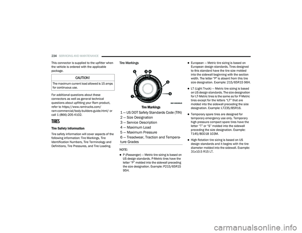
Tire Markings
Tire Markings
NOTE:
P (Passenger) — Metric tire sizing is based on
US design standards. P-Metric tires have the
letter “P” molded into the sidewall preceding
the size designation. Example: P215/65R15
95H.
European — Metric tire sizing is based on
European design standards. Tires designed
to this standard have the tire size molded
into the sidewall beginning with the section
width. The letter "P" is absent from this tire
size designation. Example: 215/65R15 96H.
LT (Light Truck) — Metric tire sizing is based
on US design standards. The size designation
for LT-Metric tires is the same as for P-Metric
tires except for the letters “LT” that are
molded into the sidewall preceding the size
designation. Example: LT235/85R16.
Temporary spare tires are designed for
temporary emergency use only. Temporary
high pressure compact spare tires have the
letter “T” or “S” molded into the sidewall
preceding the size designation. Example:
T145/80D18 103M.
High flotation tire sizing is based on US
design standards and it begins with the tire
diameter molded into the sidewall. Example:
31x10.5 R15 LT.
CAUTION!
The maximum current load allowed is 15 amps
for continuous use.
1 — US DOT Safety Standards Code (TIN)
2 — Size Designation
3 — Service Description
4 — Maximum Load
5 — Maximum Pressure
6 — Treadwear, Traction and Tempera -
ture Grades
21_VM_OM_EN_USC_t.book Page 234
Page 238 of 280

236SERVICING AND MAINTENANCE
Service Description:
95 = Load Index
A numerical code associated with the maximum load a tire can carry
H = Speed Symbol
A symbol indicating the range of speeds at which a tire can carry a load corresponding to its load index under certain operating conditions
The maximum speed corresponding to the speed symbol should only be achieved under specified operating conditions (i.e., tire pressure, vehicle
loading, road conditions, and posted speed limits)
Load Identification:
Absence of the following load identification symbols on the sidewall of the tire indicates a Standard Load (SL) tire:
XL = Extra load (or reinforced) tire, or
LL = Light load tire or
C, D, E, F, G = Load range associated with the maximum load a tire can carry at a specified pressure
Maximum Load – Maximum load indicates the maximum load this tire is designed to carry
Maximum Pressure – Maximum pressure indicates the maximum permissible cold tire inflation pressure for this tire
EXAMPLE:
21_VM_OM_EN_USC_t.book Page 236
Page 265 of 280

CUSTOMER ASSISTANCE263
Mexico
Av. Prolongacion Paseo de la Reforma, 1240
Sante Fe C.P. 05109
Mexico, D. F.
In Mexico City: (800) 505-1300
Outside Mexico City: +(52) 55 50817568
Puerto Rico And US Virgin Islands
FCA Caribbean LLC
P.O. Box 191857
San Juan 00919-1857
Phone: (866) 726-4636
Fax: (787) 782-3345
Customer Assistance For The Hearing Or
Speech Impaired (TDD/TTY)
To assist customers who have hearing
difficulties, FCA US LLC has installed special
Telecommunication Devices for the Deaf (TDD)
equipment at its customer center. Any hearing
or speech impaired customer, who has access
to a TDD or a conventional teletypewriter (TTY)
in the United States, can communicate with FCA
US LLC by dialing 1-800-380-2479. Canadian residents with hearing difficulties that
require assistance can use the special needs
relay service offered by Bell Canada. For TTY
teletypewriter users, dial 711 and for Voice
callers, dial 1-800-855-0511 to connect with a
Bell Relay Service operator.
Service Contract
You may have purchased a service contract for
a vehicle to help protect you from the high cost
of unexpected repairs after the FCA US LLC's
New Vehicle Limited Warranty expires. The
Mopar Vehicle Protection plans are the ONLY
vehicle extended protection plans authorized,
endorsed and backed by FCA US LLC to provide
additional protection beyond your vehicle’s
warranty. If you purchased a Mopar Vehicle
Protection Plan, you will receive Plan Provisions
and an Owner Identification Card in the mail
within three weeks of the vehicle delivery date.
If you have any questions about the service
contract, call FCA US LLC's Service Contract
National Customer Hotline at 1-800-521-9922
(Canadian residents, call (800) 465-2001
English / (800) 387-9983 French).
FCA US LLC is not responsible for any service
contract you may have purchased from another
manufacturer. If you require service after the
FCA US LLC New Vehicle Limited Warranty
expires, please refer to the contract documents,
and contact the person listed in those
documents.
We appreciate that you have made a major
investment when you purchased the vehicle. An
authorized dealer has also made a major
investment in facilities, tools, and training to
assure that you are absolutely delighted with
the ownership experience.
WARNING!
Engine exhaust (internal combustion engines
only), some of its constituents, and certain
vehicle components contain, or emit,
chemicals known to the State of California to
cause cancer and birth defects, or other
reproductive harm. In addition, certain fluids
contained in vehicles and certain products of
component wear contain, or emit, chemicals
known to the State of California to cause
cancer and birth defects, or other
reproductive harm.
10
21_VM_OM_EN_USC_t.book Page 263