2021 RAM PROMASTER CITY door lock
[x] Cancel search: door lockPage 37 of 280

GETTING TO KNOW YOUR VEHICLE35
WINDOWS
Power Window Controls — If Equipped
The window switches on the driver’s door
control all door windows.
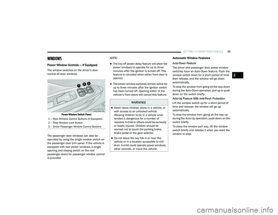
Power Window Switch Panel
The passenger door windows can also be
operated by using the single window switch on
the passenger door trim panel. If the vehicle is
equipped with rear power windows, a single
opening and closing switch on the rear
passenger doors for passenger window control
is provided. NOTE:
The key off power delay feature will allow the
power windows to operate for up to three
minutes after the ignition is turned off. This
feature is canceled when either front door is
opened.
The power window switches remain active for
up to three minutes after the ignition switch
has been turned off. Opening either of the
vehicle’s front doors will cancel this feature.
Automatic Window Features
Auto-Down Feature
The driver and passenger door power window
switches have an Auto-Down feature. Push the
window switch down for a short period of time,
then release, and the window will go down
automatically.
To stop the window from going all the way down
during the Auto-Down operation, pull up or push
down on the switch briefly.
Auto-Up Feature With Anti-Pinch Protection
Lift the window switch up for a short period of
time and release; the window will go up
automatically.
To stop the window from going all the way up
during the Auto-Up operation, push down on the
switch briefly.
To close the window part way, lift the window
switch briefly and release it when you want the
window to stop.
1 — Rear Window Control Buttons (If Equipped)
2 — Rear Window Lock Button
3 — Driver Passenger Window Control Buttons
WARNING!
Never leave children alone in a vehicle, or
with access to an unlocked vehicle.
Allowing children to be in a vehicle unat
-
tended is dangerous for a number of
reasons. A child or others could be seriously
or fatally injured. Children should be
warned not to touch the parking brake,
brake pedal or the gear selector.
Do not leave the key fob in or near the
vehicle or in a location accessible to chil -
dren. A child could operate power windows,
other controls, or move the vehicle.
2
21_VM_OM_EN_USC_t.book Page 35
Page 39 of 280

GETTING TO KNOW YOUR VEHICLE37
HOOD
Opening
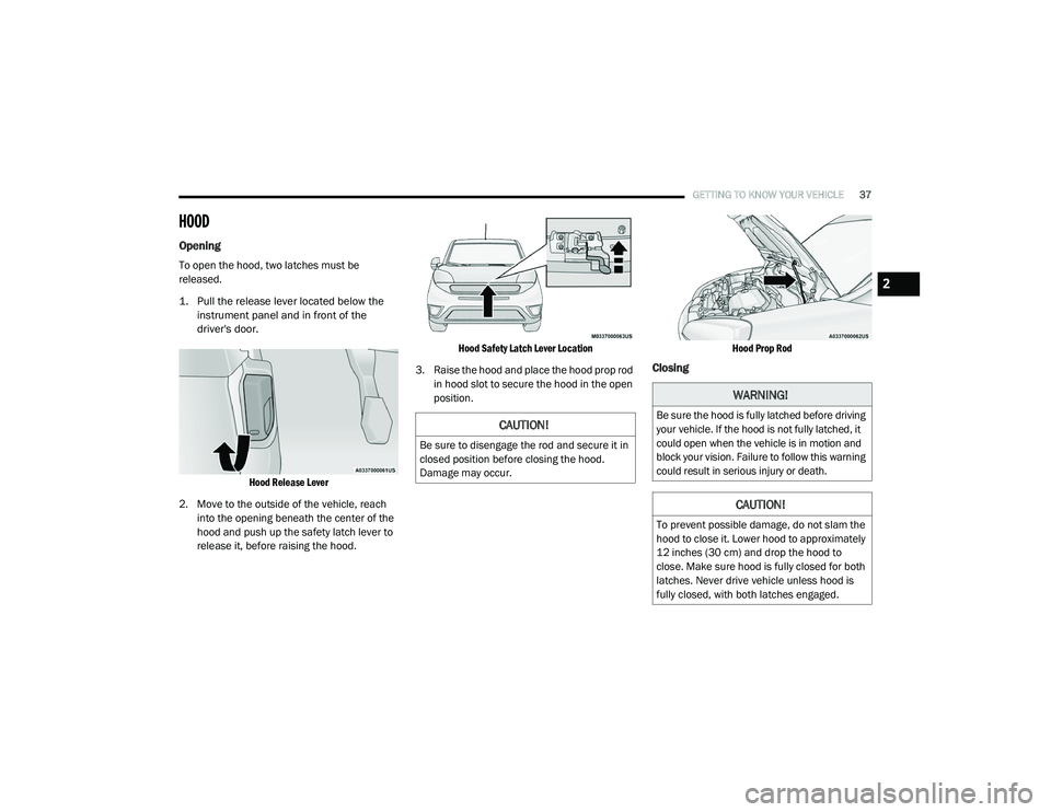
To open the hood, two latches must be
released.
1. Pull the release lever located below the
instrument panel and in front of the
driver's door.
Hood Release Lever
2. Move to the outside of the vehicle, reach into the opening beneath the center of the
hood and push up the safety latch lever to
release it, before raising the hood.
Hood Safety Latch Lever Location
3. Raise the hood and place the hood prop rod in hood slot to secure the hood in the open
position.
Hood Prop Rod
Closing
CAUTION!
Be sure to disengage the rod and secure it in
closed position before closing the hood.
Damage may occur.
WARNING!
Be sure the hood is fully latched before driving
your vehicle. If the hood is not fully latched, it
could open when the vehicle is in motion and
block your vision. Failure to follow this warning
could result in serious injury or death.
CAUTION!
To prevent possible damage, do not slam the
hood to close it. Lower hood to approximately
12 inches (30 cm) and drop the hood to
close. Make sure hood is fully closed for both
latches. Never drive vehicle unless hood is
fully closed, with both latches engaged.
2
21_VM_OM_EN_USC_t.book Page 37
Page 76 of 280

74STARTING AND OPERATING
When displayed, static grid lines will illustrate
the width of the vehicle and will show separate
zones that will help indicate the distance to the
rear of the vehicle. The following table shows
the approximate distances for each zone:
NOTE:
If snow, ice, mud, or any foreign substance
builds up on the camera lens, clean the lens,
rinse with water, and dry with a soft cloth. Do
not cover the lens.
REFUELING THE VEHICLE
The gas cap is located on the left side of the
vehicle. If the gas cap is lost or damaged, be
sure the replacement cap is for use with this
vehicle.
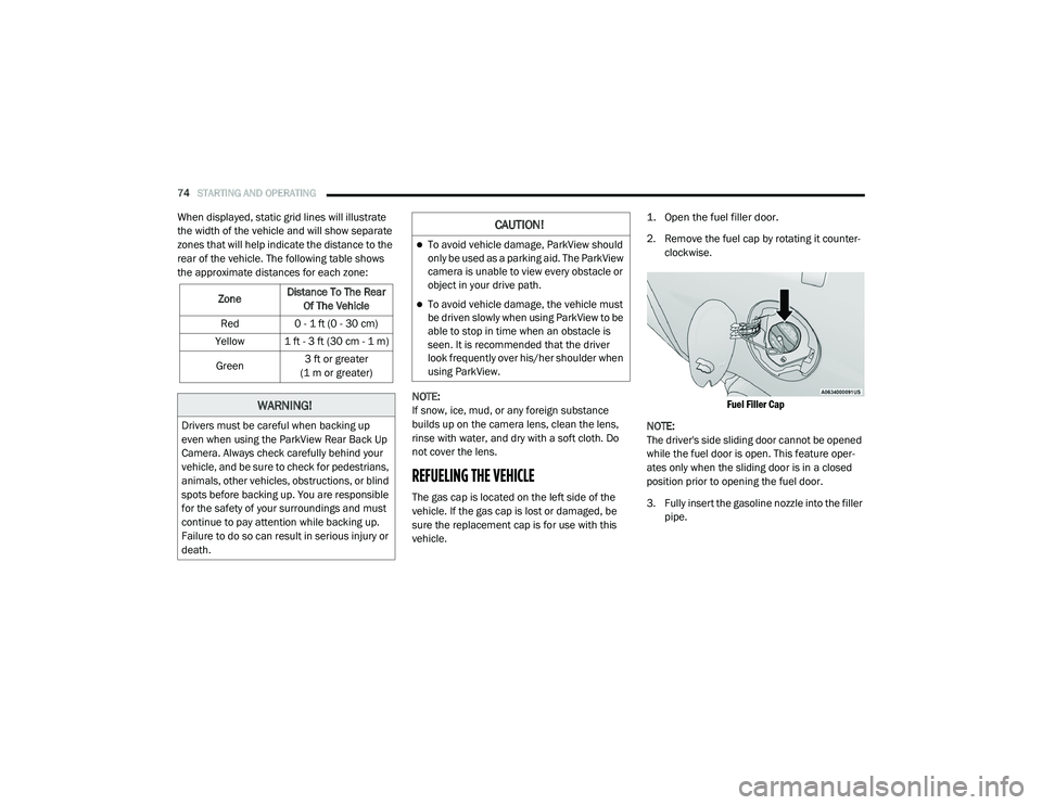
1. Open the fuel filler door.
2. Remove the fuel cap by rotating it counter
-
clockwise.
Fuel Filler Cap
NOTE:
The driver's side sliding door cannot be opened
while the fuel door is open. This feature oper -
ates only when the sliding door is in a closed
position prior to opening the fuel door.
3. Fully insert the gasoline nozzle into the filler pipe.
Zone
Distance To The Rear
Of The Vehicle
Red 0 - 1 ft (0 - 30 cm)
Yellow 1 ft - 3 ft (30 cm - 1 m)
Green 3 ft or greater
(1 m or greater)
WARNING!
Drivers must be careful when backing up
even when using the ParkView Rear Back Up
Camera. Always check carefully behind your
vehicle, and be sure to check for pedestrians,
animals, other vehicles, obstructions, or blind
spots before backing up. You are responsible
for the safety of your surroundings and must
continue to pay attention while backing up.
Failure to do so can result in serious injury or
death.
CAUTION!
To avoid vehicle damage, ParkView should
only be used as a parking aid. The ParkView
camera is unable to view every obstacle or
object in your drive path.
To avoid vehicle damage, the vehicle must
be driven slowly when using ParkView to be
able to stop in time when an obstacle is
seen. It is recommended that the driver
look frequently over his/her shoulder when
using ParkView.
21_VM_OM_EN_USC_t.book Page 74
Page 95 of 280

MULTIMEDIA93
Doors & Locks
When the Doors & Locks button is pressed on the touchscreen, the system displays the options related to locking and unlocking the vehicle’s doors.
Key Off Options
When the Key Off Option button is pressed on the touchscreen, the system displays the options related to vehicle shut off. These settings will only
activate when the ignition is set to OFF.
Setting Name Description
Sound Horn With Lock This setting will sound the horn when the key fob’s Lock button is pushed.
The “Off” setting will not sound the horn. The “1st Press” setting will
sound the horn when the Lock button is pushed once. The “2nd Press”
setting will sound the horn when the Lock button is pushed twice.
Auto Door Locks This setting will allow you to change if the doors lock automatically when
the vehicle reaches speeds of 12 mph (20 km/h).
Setting Name
Description
Radio Off Delay This setting will allow you to set the amount of time the radio remains on
after the vehicle has been turned off. The “0 min” setting will shut the
radio off the moment the vehicle is turned off. The “20 min” setting will
leave the radio on for 20 minutes after the vehicle has been turned off or
until one of the doors has been opened.
5
21_VM_OM_EN_USC_t.book Page 93
Page 170 of 280

168SAFETY
Enhanced Accident Response System
In the event of an impact, if the communication
network remains intact, and the power remains
intact, depending on the nature of the event,
the Occupant Restraint Controller (ORC) will
determine whether to have the Enhanced
Accident Response System perform the
following functions:
Cut off fuel to the engine (if equipped)
Cut off battery power to the electric motor (if
equipped)
Flash hazard lights as long as the battery has
power
Turn on the interior lights, which remain on
as long as the battery has power or for
15 minutes from the intervention of the
Enhanced Accident Response System
Unlock the power door locks
Your vehicle may also be designed to perform
any of these other functions in response to the
Enhanced Accident Response System:
Turn off the Fuel Filter Heater, Turn off the
HVAC Blower Motor, Close the HVAC Circula -
tion Door
Cut off battery power to the:
Engine
Electric Motor (if equipped)
Electric Power Steering
Brake booster
Electric park brake
Automatic transmission gear selector
Horn
Front wiper
Headlamp washer pump
NOTE:
After an accident, remember to cycle the igni -
tion to the STOP/OFF position and remove the
key from the ignition switch to avoid draining
the battery. Carefully check the vehicle for fuel
leaks in the engine compartment and on the
ground near the engine compartment and fuel
tank before resetting the system and starting
the engine. If there are no fuel leaks or damage
to the vehicle electrical devices (e.g. headlights)
after an accident, reset the system by following
the procedure described below. If you have any
doubt, contact an authorized dealer.
Enhanced Accident Response System Reset
Procedure
In order to reset the Enhanced Accident
Response System functions after an event, the
ignition switch must be changed from ignition
AVV/START or MAR/RUN to ignition STOP/OFF.
Carefully check the vehicle for fuel leaks in the
engine compartment and on the ground near
the engine compartment and fuel tank before
resetting the system and starting the engine.
After a crash, if the vehicle will not start after
performing the reset procedure, the vehicle
must be towed to an authorized dealer to be
inspected and to have the Enhanced Accident
Response System reset.
21_VM_OM_EN_USC_t.book Page 168
Page 189 of 280

SAFETY187
Periodic Safety Checks You Should Make
Outside The Vehicle
Tires
Examine tires for excessive tread wear and
uneven wear patterns. Check for stones, nails,
glass, or other objects lodged in the tread or
sidewall. Inspect the tread for cuts and cracks.
Inspect sidewalls for cuts, cracks, and bulges.
Check the lug nut/bold torque for tightness.
Check the tires (including spare) for proper cold
inflation pressure.
Lights
Have someone observe the operation of brake
lights and exterior lights while you work the
controls. Check turn signal and high beam
indicator lights on the instrument panel.
Door Latches
Check for proper closing, latching, and locking.
Fluid Leaks
Check area under the vehicle after overnight
parking for fuel, coolant, oil, or other fluid leaks.
Also, if gasoline fumes are detected or if fuel or
brake fluid leaks are suspected, the cause
should be located and corrected immediately.
NEVER place any objects under the floor
mat (e.g., towels, keys, etc.). These objects
could change the position of the floor mat
and may cause interference with the accel -
erator, brake, or clutch pedals.
If the vehicle carpet has been removed and
re-installed, always properly attach carpet
to the floor and check the floor mat
fasteners are secure to the vehicle carpet.
Fully depress each pedal to check for inter -
ference with the accelerator, brake, or
clutch pedals then re-install the floor mats.
It is recommended to only use mild soap
and water to clean your floor mats. After
cleaning, always check your floor mat has
been properly installed and is secured to
your vehicle using the floor mat fasteners
by lightly pulling mat.
WARNING! (Continued)
6
21_VM_OM_EN_USC_t.book Page 187
Page 194 of 280

192IN CASE OF EMERGENCY
Interior Fuses
The interior fuse panel is part of the Body
Control Module (BCM) and is located on the
driver's side under the instrument panel.
Fuse Panel CoverFuse Panel Cavity Locations
CavityMini Fuse Description
F535 Amp Beige KL 30 (+30) - IPC, FTM
F38 20 Amp Yellow Central Doors Locking
F36 15 Amp Blue KL 30 (+30) - TPMS, EOBD, HVAC, Radio, USB, SGW
F43 15 Amp Blue Bi-Directional Washer Pump
F48 20 Amp Yellow Passenger Power Windows
F50 7.5 Amp Brown KL 15 (+15) - Air-Bag
F51 7.5 Amp Brown KL 15 (+15) - External Mirror Adjustment Command, HVAC, RVC, HWB Coils
F37 5 Amp Beige KL 15 (+15) - Brake Pedal Switch (N.O.), IPC, Brake Pedal Switch (N.C.)
F49 5 Amp Beige KL 15 (+15) - PAM, CSS Lighting, TTM, SGW, and Heaters Light, ECM Backlighting
F31 5 Amp Beige KL 15a (INT A) - HWB, MCO
F47 20 Amp Yellow Driver Power Windows
21_VM_OM_EN_USC_t.book Page 192
Page 197 of 280

IN CASE OF EMERGENCY195
2. To access the winch mechanism open the
rear doors of the vehicle to expose the
winch mechanism access hole. Install the
winch extension into the winch mechanism.
Winch LocationJack Tools Winch Location
3. Rotate the wheel wrench handle counter -
clockwise until the spare tire is on the
ground with enough cable slack to allow you
to pull it out from under the vehicle.
Lowering The Spare Tire
NOTE:
The winch mechanism is designed for use with
the winch extension only. Use of an air wrench
or other power tools is not recommended and
can damage the winch.
4. Pull the spare tire out from under the
vehicle to gain access to the spare tire
retainer.
Spare Tire
1 — Wrench Handle
2 — Winch Extension
7
21_VM_OM_EN_USC_t.book Page 195