2021 RAM PROMASTER CITY ad blue
[x] Cancel search: ad bluePage 5 of 280

3
INSTRUMENT CLUSTER DISPLAY ......................44 Location And Controls ................................. 45
Change Engine Oil — If Equipped................ 46
Instrument Cluster Display Menu Items..... 46
TRIP COMPUTER ...................................................47
Trip Button.................................................... 48
Trip Functions ............................................. 48
Values Displayed ......................................... 49
WARNING LIGHTS AND MESSAGES ..................49
Red Warning Lights...................................... 49
Yellow Warning Lights ................................. 52
Green Indicator Lights ................................. 55
Blue Indicator Lights .................................... 56
ONBOARD DIAGNOSTIC SYSTEM — OBD II .......56
Onboard Diagnostic System (OBD II)
Cybersecurity................................................ 56
EMISSIONS INSPECTION AND MAINTENANCE
PROGRAMS ...........................................................57
STARTING AND OPERATING
STARTING THE ENGINE .......................................58
Automatic Transmission .............................. 58
Normal Starting ............................................ 58
Cold Weather Operation ............................. 58
Extended Park Starting................................ 58
If Engine Fails To Start ................................ 59
After Starting ................................................ 59
ENGINE BLOCK HEATER — IF EQUIPPED ...........59
ENGINE BREAK-IN RECOMMENDATIONS .........60
PARKING BRAKE .................................................60 AUTOMATIC TRANSMISSION ............................. 62
Key Ignition Park Interlock .......................... 62
Brake/Transmission Shift Interlock (BTSI)
System ......................................................... 63 Nine-Speed Automatic Transmission ........ 63
POWER STEERING .............................................. 67
Power Steering Fluid Check ....................... 68
CRUISE CONTROL — IF EQUIPPED ..................... 68
To Activate.................................................... 69
To Set A Desired Speed............................... 69
To Vary The Speed Setting .......................... 69
To Accelerate For Passing ........................... 69
To Resume Speed ....................................... 70
To Deactivate .............................................. 70
PARKSENSE REAR PARK ASSIST —
IF EQUIPPED ......................................................... 70
ParkSense Rear Park Assist Sensors ......... 70
ParkSense Rear Park Assist Alerts ............. 71
ParkSense Rear Park Assist Failure
Indications.................................................... 72 Cleaning The ParkSense Rear Park Assist
System .......................................................... 72 ParkSense Rear Park Assist System Usage
Precautions .................................................. 72
PARKVIEW REAR BACK UP CAMERA ............... 73
REFUELING THE VEHICLE ................................... 74 VEHICLE LOADING ................................................75
Vehicle Certification Label .......................... 75
Gross Vehicle Weight Rating (GVWR) ......... 76
Gross Axle Weight Rating (GAWR) ............. 76
Tire Size ........................................................ 76
Rim Size ....................................................... 76
Inflation Pressure ........................................ 76
Curb Weight ................................................. 76
Overloading .................................................. 76
Loading......................................................... 76
TRAILER TOWING .................................................77
Common Towing Definitions ....................... 77
Trailer Hitch Classification .......................... 78
Trailer Towing Weights (Maximum Trailer
Weight Ratings) ........................................... 79 Trailer And Tongue Weight ......................... 79
Towing Requirements ................................ 79
Towing Tips ................................................. 82
RECREATIONAL TOWING (BEHIND
MOTORHOME) ......................................................83
Towing This Vehicle Behind Another
Vehicle .......................................................... 83 Recreational Towing — Automatic
Transmission................................................ 83
DRIVING TIPS ........................................................84
Driving On Slippery Surfaces ..................... 84
Driving Through Water ............................... 84
21_VM_OM_EN_USC_t.book Page 3
Page 11 of 280

9
Yellow Warning Lights
Anti-Lock Brake System (ABS) Warning Light Úpage 52
Low Fuel Warning Light Úpage 52
Generic Warning Light Úpage 52
Tire Pressure Monitoring System (TPMS) Warning Light Ú page 53
Vehicle Security Warning Light Úpage 54
Engine Check/Malfunction Indicator Warning Light (MIL)
Ú page 54
Electronic Stability Control (ESC) Warning Light — If Equipped Ú page 55
Electronic Stability Control (ESC) OFF Warning Light — If Equipped Úpage 55
Green Indicator Lights
Turn Signal Indicator Lights
Úpage 55
Park/Headlight On Indicator Light Úpage 55
Front Fog Indicator Light — If Equipped Úpage 55
Cruise Control Indicator Light — If Equipped Úpage 55
Blue Indicator Lights
High Beam Indicator Light
Úpage 56
1
21_VM_OM_EN_USC_t.book Page 9
Page 34 of 280
32GETTING TO KNOW YOUR VEHICLE
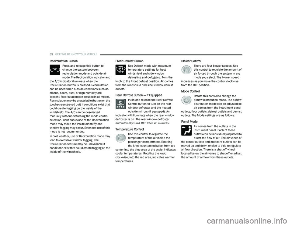
Recirculation Button
Press and release this button to
change the system between
recirculation mode and outside air
mode. The Recirculation indicator and
the A/C indicator illuminate when the
Recirculation button is pressed. Recirculation
can be used when outside conditions such as
smoke, odors, dust, or high humidity are
present. Recirculation can be used in all modes.
Recirculation may be unavailable (button on the
touchscreen greyed out) if conditions exist that
could create fogging on the inside of the
windshield. The A/C can be deselected
manually without disturbing the mode control
selection. Continuous use of the Recirculation
mode may make the inside air stuffy and
window fogging may occur. Extended use of this
mode is not recommended.
In cold weather, use of Recirculation mode may
lead to excessive window fogging. The
Recirculation feature may be unavailable if
conditions exist that could create fogging on the
inside of the windshield.
Front Defrost Button
Use Defrost mode with maximum
temperature settings for best
windshield and side window
defrosting and defogging. Turn the
knob to the Front Defrost position. Air comes
from the windshield and side window demist
outlets.
Rear Defrost Button — If Equipped
Push and release the Rear Defrost
Control button to turn on the rear
window defroster and the heated
outside mirrors (if equipped). An
indicator will illuminate when the rear window
defroster is on. The rear window defroster
automatically turns OFF after 20 minutes.
Temperature Control
Use this control to regulate the
temperature of the air inside the
passenger compartment. Rotating
the knob counterclockwise, from top
center into the blue area of the scale, indicates
cooler temperatures. Rotating the knob
clockwise, into the red area, indicates warmer
temperatures.
Blower Control
There are four blower speeds. Use
this control to regulate the amount of
air forced through the system in any
mode you select. The blower speed
increases as you move the control clockwise
from the OFF position.
Mode Control
Rotate this control to change the
airflow distribution mode. The airflow
distribution mode can be adjusted so
air comes from the instrument panel
outlets, floor outlets, defrost outlets and demist
outlets. The Mode settings are as follows:
Panel Mode
Air comes from the outlets in the
instrument panel. Each of these
outlets can be individually adjusted to
direct the flow of air. The air vanes of
the center outlets and outboard outlets can be
moved up and down or side to side to regulate
airflow direction. There is a shut off wheel
located below the air vanes to shut off or adjust
the amount of airflow from these outlets.
21_VM_OM_EN_USC_t.book Page 32
Page 43 of 280
GETTING TO KNOW YOUR VEHICLE41
(Continued)
(Continued)
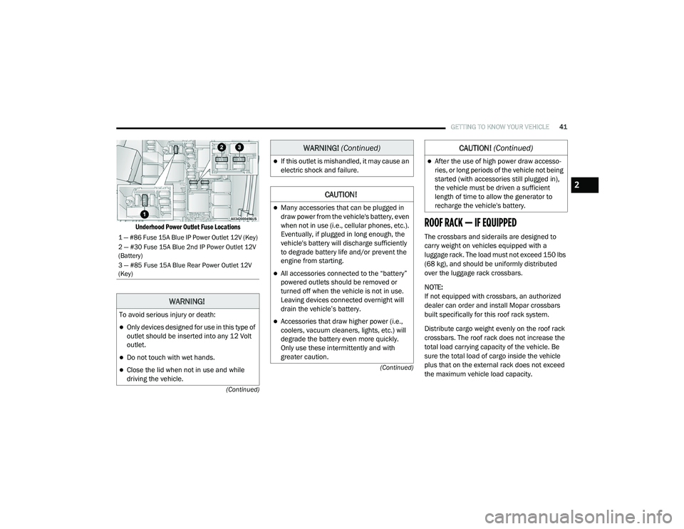
Underhood Power Outlet Fuse Locations
ROOF RACK — IF EQUIPPED
The crossbars and siderails are designed to
carry weight on vehicles equipped with a
luggage rack. The load must not exceed 150 lbs
(68 kg), and should be uniformly distributed
over the luggage rack crossbars.
NOTE:
If not equipped with crossbars, an authorized
dealer can order and install Mopar crossbars
built specifically for this roof rack system.
Distribute cargo weight evenly on the roof rack
crossbars. The roof rack does not increase the
total load carrying capacity of the vehicle. Be
sure the total load of cargo inside the vehicle
plus that on the external rack does not exceed
the maximum vehicle load capacity.1 — #86 Fuse 15A Blue IP Power Outlet 12V (Key)
2 — #30 Fuse 15A Blue 2nd IP Power Outlet 12V
(Battery)
3 — #85 Fuse 15A Blue Rear Power Outlet 12V
(Key)
WARNING!
To avoid serious injury or death:
Only devices designed for use in this type of
outlet should be inserted into any 12 Volt
outlet.
Do not touch with wet hands.
Close the lid when not in use and while
driving the vehicle.
If this outlet is mishandled, it may cause an
electric shock and failure.
CAUTION!
Many accessories that can be plugged in
draw power from the vehicle's battery, even
when not in use (i.e., cellular phones, etc.).
Eventually, if plugged in long enough, the
vehicle's battery will discharge sufficiently
to degrade battery life and/or prevent the
engine from starting.
All accessories connected to the “battery”
powered outlets should be removed or
turned off when the vehicle is not in use.
Leaving devices connected overnight will
drain the vehicle’s battery.
Accessories that draw higher power (i.e.,
coolers, vacuum cleaners, lights, etc.) will
degrade the battery even more quickly.
Only use these intermittently and with
greater caution.
WARNING! (Continued)
After the use of high power draw accesso -
ries, or long periods of the vehicle not being
started (with accessories still plugged in),
the vehicle must be driven a sufficient
length of time to allow the generator to
recharge the vehicle's battery.
CAUTION! (Continued)
2
21_VM_OM_EN_USC_t.book Page 41
Page 58 of 280

56GETTING TO KNOW YOUR INSTRUMENT PANEL
Blue Indicator Lights
High Beam Indicator Light
This indicator light will illuminate to
indicate that the high beam
headlights are on. With the low beams
activated, push the multifunction
lever forward (toward the front of the vehicle) to
turn on the high beams. Pull the multifunction
lever rearward (toward the rear of the vehicle) to
turn off the high beams. If the high beams are
off, pull the lever toward you for a temporary
high beam on, “flash to pass” scenario.
ONBOARD DIAGNOSTIC SYSTEM — OBD II
Your vehicle is equipped with a sophisticated
Onboard Diagnostic system called OBD II. This
system monitors the performance of the
emissions, engine, and transmission control
systems. When these systems are operating
properly, your vehicle will provide excellent
performance and fuel economy, as well as
engine emissions well within current
government regulations.
If any of these systems require service, the OBD
II system will turn on the Malfunction Indicator
Light (MIL). It will also store diagnostic codes
and other information to assist your service technician in making repairs. Although your
vehicle will usually be drivable and not need
towing, see an authorized dealer for service as
soon as possible.
Onboard Diagnostic System (OBD II)
Cybersecurity
Your vehicle is required to have an Onboard
Diagnostic system (OBD II) and a connection
port to allow access to information related to
the performance of your emissions controls.
Authorized service technicians may need to
access this information to assist with the
diagnosis and service of your vehicle and
emissions system Ú
page 86.
CAUTION!
Prolonged driving with the MIL on could
cause further damage to the emission
control system. It could also affect fuel
economy and driveability. The vehicle must
be serviced before any emissions tests can
be performed.
If the MIL is flashing while the vehicle is
running, severe catalytic converter damage
and power loss will soon occur. Immediate
service is required.
WARNING!
ONLY an authorized service technician
should connect equipment to the OBD II
connection port in order to read the VIN,
diagnose, or service your vehicle.
If unauthorized equipment is connected to
the OBD II connection port, such as a
driver-behavior tracking device, it may:
Be possible that vehicle systems,
including safety related systems, could
be impaired or a loss of vehicle control
could occur that may result in an acci -
dent involving serious injury or death.
Access, or allow others to access, infor -
mation stored in your vehicle systems,
including personal information.
21_VM_OM_EN_USC_t.book Page 56
Page 97 of 280
MULTIMEDIA95
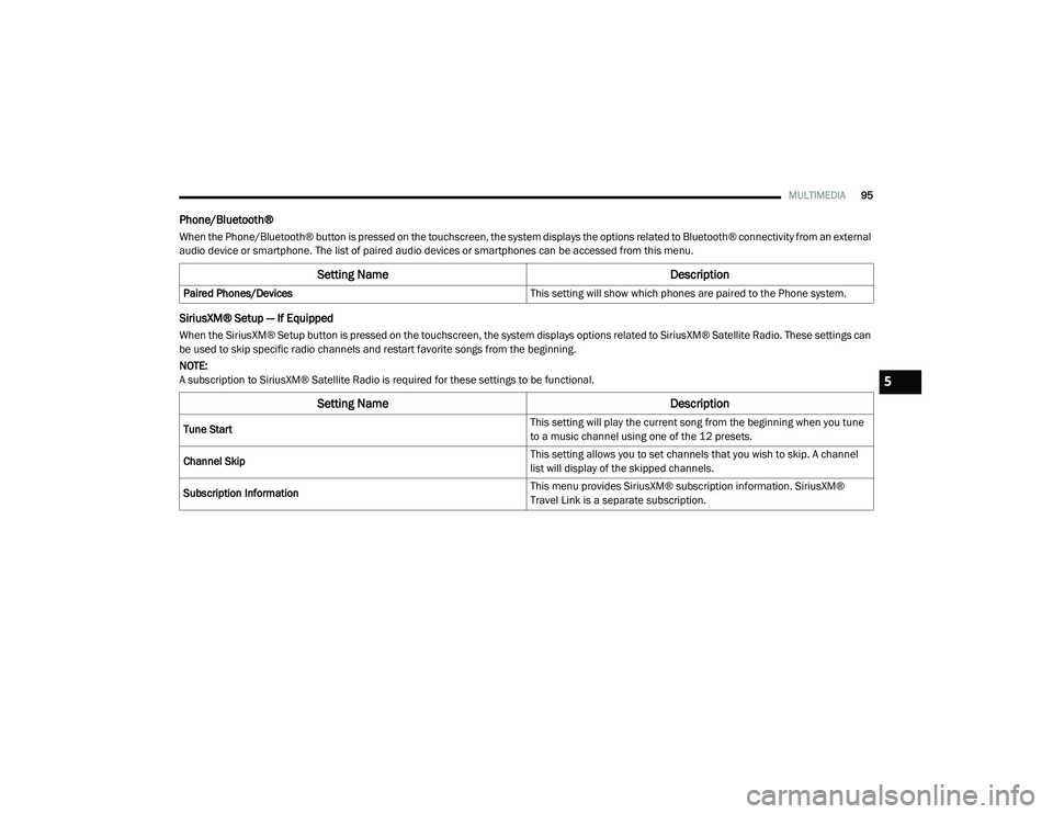
Phone/Bluetooth®
When the Phone/Bluetooth® button is pressed on the touchscreen, the system displays the options related to Bluetooth® connectivity from an external
audio device or smartphone. The list of paired audio devices or smartphones can be accessed from this menu.
SiriusXM® Setup — If Equipped
When the SiriusXM® Setup button is pressed on the touchscreen, the system displays options related to SiriusXM® Satellite Radio. These settings can
be used to skip specific radio channels and restart favorite songs from the beginning.
NOTE:
A subscription to SiriusXM® Satellite Radio is required for these settings to be functional.
Setting Name Description
Paired Phones/Devices This setting will show which phones are paired to the Phone system.
Setting NameDescription
Tune Start This setting will play the current song from the beginning when you tune
to a music channel using one of the 12 presets.
Channel Skip This setting allows you to set channels that you wish to skip. A channel
list will display of the skipped channels.
Subscription Information This menu provides SiriusXM® subscription information. SiriusXM®
Travel Link is a separate subscription.
5
21_VM_OM_EN_USC_t.book Page 95
Page 98 of 280
96MULTIMEDIA
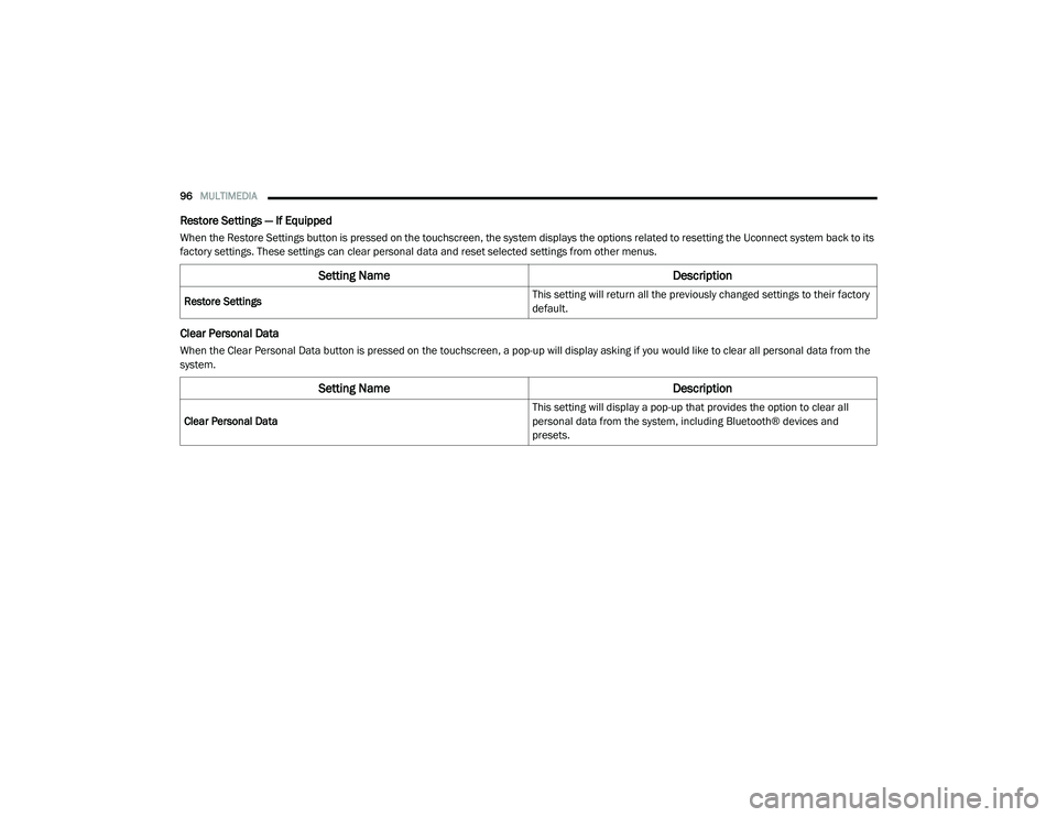
Restore Settings — If Equipped
When the Restore Settings button is pressed on the touchscreen, the system displays the options related to resetting the Uconnect system back to its
factory settings. These settings can clear personal data and reset selected settings from other menus.
Clear Personal Data
When the Clear Personal Data button is pressed on the touchscreen, a pop-up will display asking if you would like to clear all personal data from the
system.
Setting Name Description
Restore Settings This setting will return all the previously changed settings to their factory
default.
Setting Name
Description
Clear Personal Data This setting will display a pop-up that provides the option to clear all
personal data from the system, including Bluetooth® devices and
presets.
21_VM_OM_EN_USC_t.book Page 96
Page 109 of 280
MULTIMEDIA107
Radio Voice Commands
Use your voice to quickly get to the AM, FM, or
SiriusXM® Satellite Radio stations you would
like to hear. (Subscription or included
SiriusXM® Satellite Radio trial required.)
Push the VR button and wait for the beep to
say a command. See some examples below.
“Tune to ninety-five-point-five FM”
“Tune to Satellite Channel Hits 1”
Did You Know: At any time, if you are not sure of
what to say or want to learn a Voice Command,
push the VR button and say “ Help”. The
system provides you with a list of commands.
Media Mode
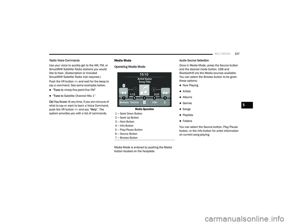
Operating Media Mode
Media Operation
Media Mode is entered by pushing the Media
button located on the faceplate. Audio Source Selection
Once in Media Mode, press the Source button
and the desired mode button. USB and
Bluetooth® are the Media sources available.
You can select the Browse button to be given
these options:
Now Playing
Artists
Albums
Genres
Songs
Playlists
Folders
You can select the Source button, Play/Pause
button, or the Info button for artist information
on current song playing.
1 — Seek Down Button
2 — Seek Up Button
3 — Next Button
4 — Info Button
5 — Play/Pause Button
6 — Source Button
7 — Browse Button
5
21_VM_OM_EN_USC_t.book Page 107