Page 105 of 212

103
Practical information
7
► Insert the nozzle into the vehicle's charging
connector .
The indicator lamp in the flap comes on fixed to
indicate that the nozzle is locked.
When charging has started, the message
"CHARGING" appears on the display integrated
into the rear view mirror and the level of current
flowing into the traction battery is shown.
If this is not the case, charging has not started.
Depending on the message displayed in the rear
view mirror, proceed as follows:
–
"UNPLUG&PLUG": remove and then reinsert
the nozzle.
–
"WAITING x SEC": wait several seconds until
the message "DC CHARGE READY " appears.
Disconnection
Charging is complete when the message
"CHARGE FULL" is shown on the display
integrated into the rear view mirror.
Before disconnecting the nozzle from the
charging connector:
►
Switch off the current to the charging unit (if
applicable).
or
►
Press the locking button on the remote
control for 5 seconds.
The charging nozzle unlocks (confirmed when
the indicator lamp above the charging connector
goes out).
Accelerated charging, mode 3
When the nozzle is unlocked, the message
"PLUGGED IN" appears in the display integrated
into the rear view mirror.
►
Remove the charging nozzle within 30
seconds
.
If the charging nozzle is not removed
within 30 seconds, it automatically locks
again inside the flap and charging
recommences (the message " CHARGING"
appears on the display integrated into the rear
view mirror).
Superfast charging, mode 4
When the nozzle is unlocked, the message
"CHARGE STOP" appears on the display
integrated into the rear view mirror.
►
W
ait until the message "UNPLUG" appears,
then remove the charging nozzle.
Never try to remove the charging nozzle
when it is locked (indicator lamp on fixed)
- risk of irreversibly damaging the locking
mechanism and preventing charging of the
traction battery!
►
Replace the protective covers over the
charging connector and close the charging flap.
► Disconnect the cable from the charging unit
(if applicable).
Snow chains
In wintry conditions, snow chains improve
traction as well as the behaviour of the
vehicle when braking.
The snow chains must be fitted only to the front wheels. They must never be
fitted to "space-saver" type spare wheels.
Observe the legislation in force in your
country on the use of snow chains and
the maximum authorised speed.
Only use chains that have been designed to be
fitted to the type of wheel on the vehicle:
Original tyre size Maximum link size.
205/70 R15 16 mm
215/70 R15 12 mm
225/70 R15 16 mm
215/75 R16 12 mm
225/75 R16 16 mm
For more information, contact a PEUGEOT
dealer or a qualified workshop.
Page 106 of 212

104
Practical information
Installation tips
► To fit the snow chains during a journey, stop
the vehicle on a flat surface at the side of the
road.
►
Apply the parking brake and position any
wheel chocks under the wheels to prevent
movement of the vehicle.
►
Fit the snow chains following the instructions
provided by the manufacturer
.
►
Move off gently and drive for a few moments,
without exceeding 31
mph (50 km/h).
►
Stop the vehicle and check that the snow
chains are correctly tightened.
It is strongly recommended that you
practise fitting the snow chains on a level
and dry surface before setting off.
Avoid driving with snow chains on roads that have been cleared of snow to avoid
damaging the vehicle's tyres and the road
surface. If the vehicle is fitted with alloy
wheels, check that no part of the chain or its
fixings is in contact with the wheel rim.
Towing a trailer
The type-approved towable weights are entered
in your vehicle's registration certificate, as well
as on the manufacturer's plate.
For more information on the Technical
characteristics of the vehicle and
particularly on weights and towable loads,
refer to the corresponding section.
You will then have information on your vehicle's
ability to tow a trailer, a caravan, a boat, etc.
These values are also given in the sales
brochures.
We recommend using genuine
PEUGEOT towbars and their harnesses
that have been tested and approved from the
design stage of your vehicle, and having a
PEUGEOT dealer fit the towbar.
These genuine towbars are compatible with
the operation of the rear parking sensors and
the reversing camera, if your vehicle is so
equipped.
If the towbar is not fitted by a PEUGEOT
dealer, it must still be fitted in accordance with
the vehicle manufacturer's instructions.
Electric motor
An electric vehicle cannot under any
circumstances be fitted with a towing device.
It is therefore not possible to tow a trailer or
caravan.
Towbar with quickly detachable towball
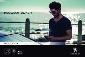
Presentation
This genuine towball can be easily and quickly
fitted or removed. These operations do not
require any tools.
Page 107 of 212

105
Practical information
7
1.Carrier
2. Connection socket
3. Safety eye
4. Detachable towball
5. Locking / unlocking wheel
6. Key lock with removable cap
7. Key reference label
For more information on the Technical
data of the vehicle, and in particular on
the weights and towed loads, refer to the
corresponding section.
A. Locked position; the locking wheel is in contact with the towball (no gap).
B. Unlocked position; the locking wheel is no longer in contact with the towball (gap of
around 5 mm).
Observe the legislation in force in the
country where you are driving.
Before each use
Check that the towball is correctly locked,
verifying the follow points:
–
the green mark on the wheel is in line with
the green mark on the towball,
–
the wheel is in contact with the towball,
–
the key lock is closed and the key removed;
the wheel can no longer be operated,
– the towball must not be able to move in its
carrier; test by shaking it with your hand.
During use
Never release the locking system with a
trailer or load carrier on the towball.
Never exceed the maximum authorised
weight for the vehicle (the Gross Vehicle
Weight - GVW), the trailer, or the sum of the
two (the Gross Train Weight - GTW).
Following use
When travelling without a trailer or load on a
towbar-mounted carrier, the towball must be
removed and the protective plug inserted in the
carrier. This measure applies particularly where
the towball might obscure visibility of the number
plate or its lighting.
Page 108 of 212

106
Practical information
Fitting the towball
► Below the rear bumper, remove the protective
plug from the carrier.
►
Insert the end of towball
4 into carrier 1 and
push it upwards; the locking will take place
automatically.
The wheel 5 turns a quarter of a turn anti-
clockwise; take care to keep your hands clear.
► Check that the mechanism has correctly
locked into place (position A ).
►
Close lock 6
using the key. ►
Always remove the key
. The key cannot be
removed when the lock is open.
►
Clip the cap onto the lock.
► Remove the protective cover from the
towball.
►
Attach the trailer to the towball.
►
Attach the cable on the trailer to safety eye
3
on the carrier.
►
Connect the trailer plug to connection
socket
2 on the carrier.
Removing the towball
► Disconnect the trailer plug from the
connection socket 2 on the carrier.
►
Detach the cable on the trailer from the safety
eye
3 on the carrier.
►
Detach the trailer from the towball.
►
Refit the protective cover to the towball.
►
Remove the cap from the lock and press it
onto the head of the key
.
►
Insert the key into lock
6.
► Open the lock using the key .
► Hold towball 4
firmly in one hand; using
the other hand, pull and turn wheel 5 fully in a
clockwise direction; do not release the wheel.
►
Extract the towball from the bottom of its
carrier
1.
►
Release the wheel; this automatically stops in
the unlocked position (position
B
).
►
Refit the protective plug to the carrier .
►
Carefully stow the towball in its bag away
from knocks and dirt.
Maintenance
Correct operation is only possible if the towball
and its carrier are kept clean.
Before cleaning the vehicle with a high-pressure
jet wash, the towball must be removed and the
protective plug fitted to the carrier.
Affix the enclosed label in a clearly visible
location, close to the carrier or in the boot.
Work on the towing device
Contact a PEUGEOT dealer or a
qualified workshop.
Page 109 of 212
 approved for the v")
107
Practical information
7Roof-mounted carrying
systems
For safety reasons and to avoid damaging the
roof, it is imperative to use a carrying system
(roof bars or roof rack) approved for the vehicle.
Roof bars can only be fitted on H1 or H2 height
versions of vans, combis and minibuses. On
minibuses, check the presence of a roof air
conditioning unit.
The carrying device must be fixed to the
anchorage points on the roof of the vehicle: 6,
8 or 10, depending on the wheelbase of the
vehicle.
Observe the fitting instructions and the
conditions of use in the guide supplied with the
carrying device.
Maximum roof load, evenly distributed:
150 kg, for all versions, within the limits
of the gross vehicle weight (GVW).
Roofs cannot be equipped with a
carrying system on H3 height versions.
Strictly observe the legal provisions in
force concerning the maximum volume
measurements.
For more information on the Technical
data of the vehicle, and in particular on
the dimensions, refer to the corresponding
section.
Bonnet
Opening
Before doing anything under the bonnet,
deactivate the Stop & Start system to
avoid the risk of injury related to an automatic
change to START mode.
Electric motor
Take care with objects or clothing that
could be caught in the blades of the cooling
fan or in certain moving components - risk of
strangulation and serious injury!
Before carrying out any work under the
bonnet, you must switch off the ignition
and
disconnect the nozzle from the charging
connector
if it is connected.
On the inside
This operation must only be done with the
vehicle stationary and the driver’s door open.
► Pull the control located on the side of the
dashboard towards you.
Page 110 of 212

108
Practical information
On the outside
► Push the lever located above the grille
upwards and lift the bonnet.
Do not open the bonnet under very windy
conditions.
When the engine is hot, handle the lever and
the stay with care (risk of burns).
► Unclip the stay and rotate it to insert it into
the first slot and then into the second slot.
Because of the presence of electrical
equipment under the bonnet, it is
recommended that exposure to water (rain,
washing, etc.) be limited.
Closing the bonnet
► Before closing the bonnet, replace the stay in
its housing.
►
Lower the bonnet and release it near the end
of its travel. Check the bonnet is locked.
Diesel engines
1. Screenwash and headlamp washer reservoir
2. Power steering fluid reservoir
3. Engine coolant reservoir
4. Brake and clutch fluid reservoir
5. Diesel fuel filter
6. Fusebox
7. Air filter
8. Dipstick
9. Engine oil filler cap
Battery connections:
+ Positive metallic terminal
- Negative metallic terminal (earth)
Diesel fuel system
This system is under very high pressure.
Page 111 of 212

109
Practical information
7All work must be carried out only by a
PEUGEOT dealer or a qualified workshop
Electric motor
1.Screenwash and headlamp washer reservoir
2. Engine coolant reservoir
3. Power steering fluid reservoir
4. Brake and clutch fluid reservoir
5. Heating
circuit fluid reservoir
6. Fusebox
Checking levels
Check all of the following levels regularly in
accordance with the manufacturer's service
schedule. Top them up if required, unless
otherwise indicated.
If a level drops significantly, have the
corresponding system checked by a PEUGEOT
dealer or a qualified workshop.
The fluids must comply with the
manufacturer's requirements and with
the vehicle's engine.
Take care when working under the bonnet, as certain areas of the engine
may be extremely hot (risk of burns) and the
cooling fan could start at any time (even with
the ignition off).
If the engine cover is to be removed /
refitted, handle it with care to avoid
damaging the mounting clips.
Used products
Avoid prolonged contact of used oil or fluids with the skin.
Most of these fluids are harmful to health and
very corrosive.
Do not discard used oil or fluids into
sewers or onto the ground.
Empty used oil into the containers reserved
for this purpose at a PEUGEOT dealer or a
qualified workshop.
Engine oil
The level is checked, with the engine having been switched off for at least 30
minutes and on level ground, using the dipstick.
It is normal to top up the oil level between two
services (or oil changes). It is recommended
that you check the level, and top up if necessary,
every 3,000 miles (5,000 km).
In order to maintain the reliability of the
engine and emissions control system,
never use additives in the engine oil.
Checking using the dipstick
For the location of the dipstick, please refer
to the illustration of the corresponding engine
compartment.
►
Grasp the dipstick by its coloured grip and
pull it out completely
.
►
Wipe the end of the dipstick using a clean,
lint-free cloth.
► Reinsert the dipstick and push fully down,
then pull it out again to visually check the oil
level: the correct level is between marks A
(max)
and B (min).
Do not start the engine if the level is:
–
above mark
A: contact a PEUGEOT dealer or
a qualified workshop.
–
below mark B
: top up the engine oil
immediately.
Oil grade
Before topping up or changing the engine
oil, check that the oil is suitable for the engine
and complies with the recommendations in
Page 112 of 212
.
Use of non-recommended oil may invalidate
the contractual")
11 0
Practical information
the service schedule supplied with the vehicle
(or available from your PEUGEOT dealer and
qualified workshops).
Use of non-recommended oil may invalidate
the contractual warranty in the event of
engine failure.
Topping up the engine oil level
► Remove the dipstick before topping up.
► Recover the oil filler neck.
►
Unscrew the filler cap.
►
Install the oil filler neck in the filler hole.
►
T
op up with oil.
►
Remove the oil filler neck from the filler hole.
►
Replace the filler cap.
► Replace the dipstick.
Brake fluid
The level of this fluid should be close to the "MAX" mark. If not, check the brake
pad wear.
To know how often the brake fluid should be
replaced, refer to the manufacturer's servicing
schedule.
If topping up, clean the cap before
replacing it. Use only DOT4 brake fluid
from a sealed canister.
Power steering fluid
The level of this fluid should be close to the "MAX" mark. Check it, with the
vehicle parked on level ground and with the
engine cold, by reading the level on the filler
neck.
Unscrew the cap secured to the dipstick. To
access the reservoir cap, remove the protective
cover by turning its three fixing screws a quarter
turn, then remove the second cover placed on
the cap.
Engine coolant
(Diesel)
It is normal to top up this fluid between
two services.
The check and top-up must only be done with
the engine cold. A level of coolant that is too low risks causing
major damage to the engine; the coolant level
must be close to the "MAX" mark without ever
going above it.
If the level is close to or below the "
MIN" mark, it
is essential to top it up.
When the engine is hot, the temperature of the
coolant is regulated by the fan.
As the cooling system is pressurised, wait at
least one hour after switching off the engine
before carrying out any work.
To gain access to the reservoir cap, remove the
protective cover by turning its three fixing screws
a quarter of a turn.
In order to avoid the risk of scalding if you need
to top up in an emergency, wrap a cloth around
the cap and unscrew the cap by two turns to
allow the pressure to drop.
Once the pressure has dropped, remove the cap
and top up to the required level.
 1
1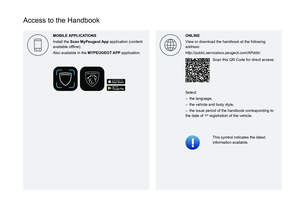 2
2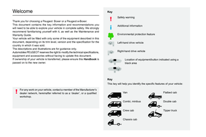 3
3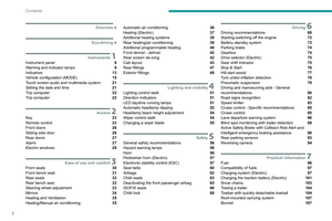 4
4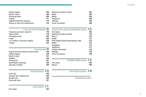 5
5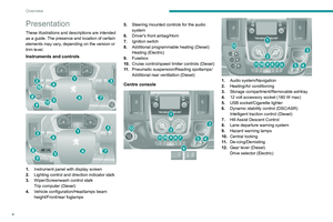 6
6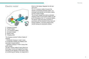 7
7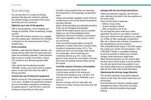 8
8 9
9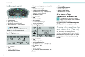 10
10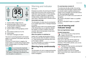 11
11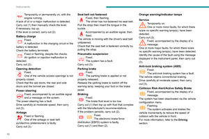 12
12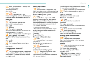 13
13 14
14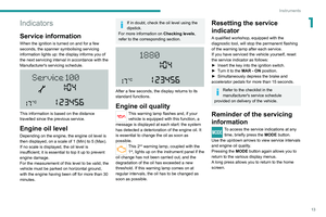 15
15 16
16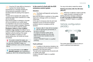 17
17 18
18 19
19 20
20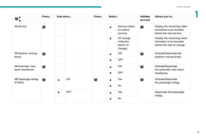 21
21 22
22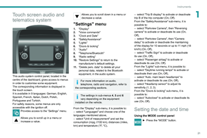 23
23 24
24 25
25 26
26 27
27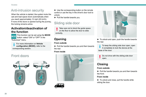 28
28 29
29 30
30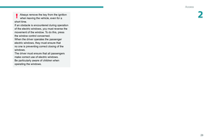 31
31 32
32 33
33 34
34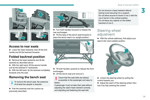 35
35 36
36 37
37 38
38 39
39 40
40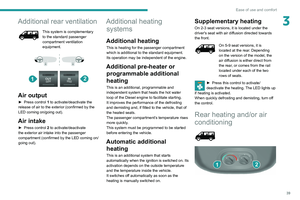 41
41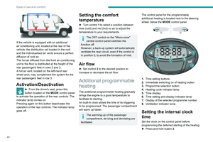 42
42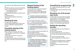 43
43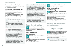 44
44 45
45 46
46 47
47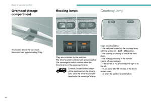 48
48 49
49 50
50 51
51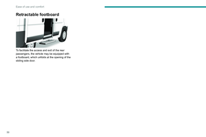 52
52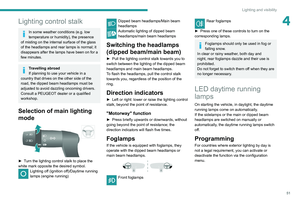 53
53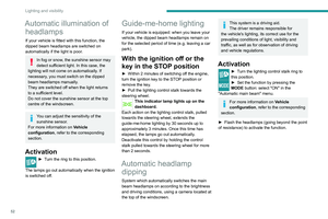 54
54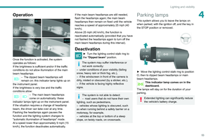 55
55 56
56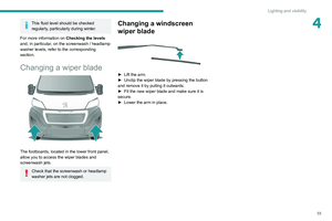 57
57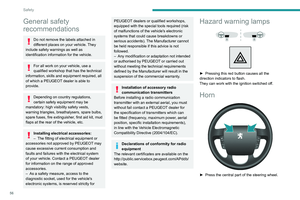 58
58 59
59 60
60 61
61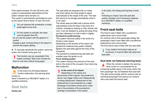 62
62 63
63 64
64 65
65 66
66 67
67 68
68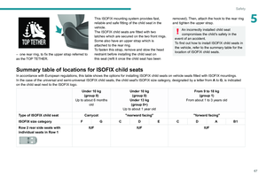 69
69 70
70 71
71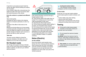 72
72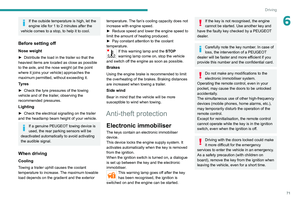 73
73 74
74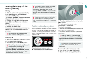 75
75 76
76 77
77 78
78 79
79 80
80 81
81 82
82 83
83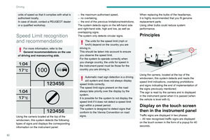 84
84 85
85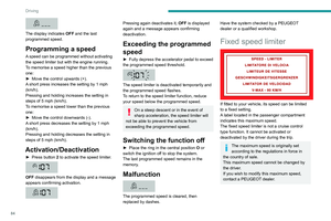 86
86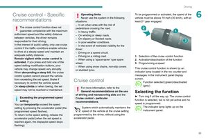 87
87 88
88 89
89 90
90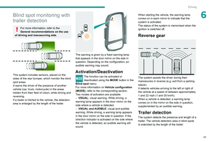 91
91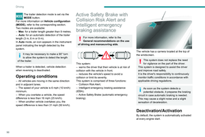 92
92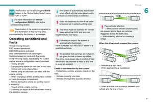 93
93 94
94 95
95 96
96 97
97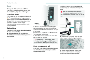 98
98 99
99 100
100 101
101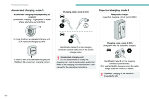 102
102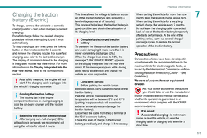 103
103 104
104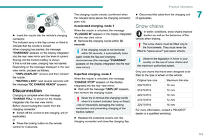 105
105 106
106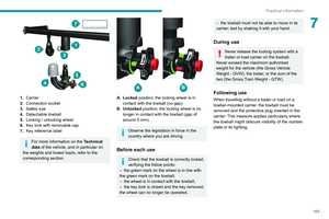 107
107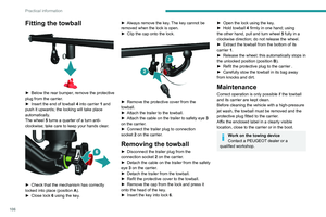 108
108 109
109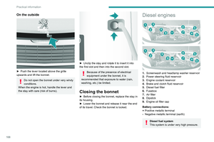 110
110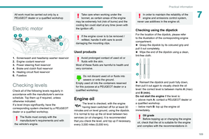 111
111 112
112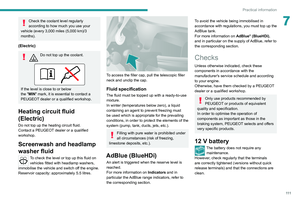 113
113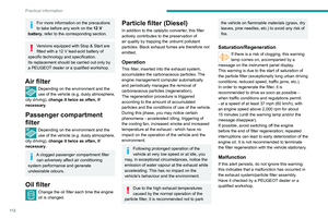 114
114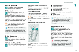 115
115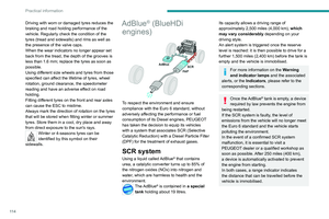 116
116 117
117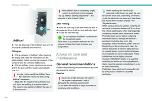 118
118 119
119 120
120 121
121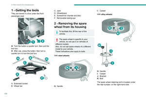 122
122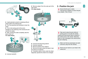 123
123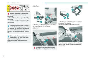 124
124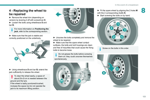 125
125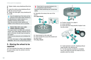 126
126 127
127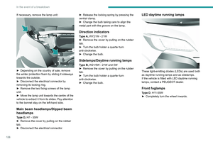 128
128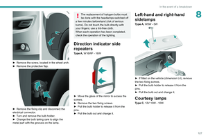 129
129 130
130 131
131 132
132 133
133 134
134 135
135 136
136 137
137 138
138 139
139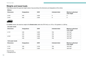 140
140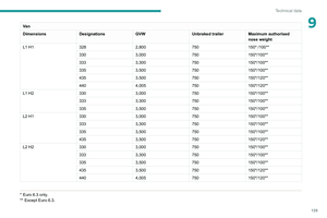 141
141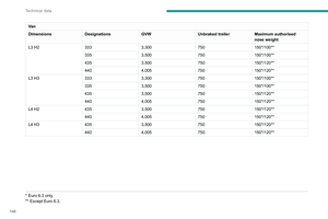 142
142 143
143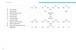 144
144 145
145 146
146 147
147 148
148 149
149 150
150 151
151 152
152 153
153 154
154 155
155 156
156 157
157 158
158 159
159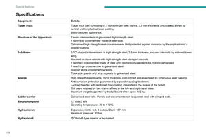 160
160 161
161 162
162 163
163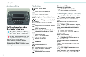 164
164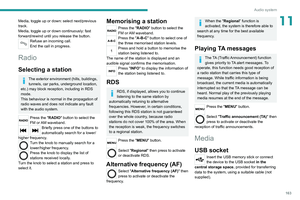 165
165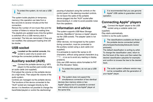 166
166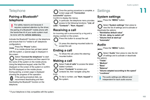 167
167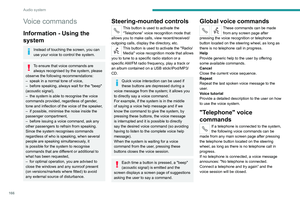 168
168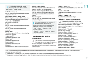 169
169 170
170 171
171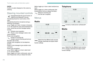 172
172 173
173 174
174 175
175 176
176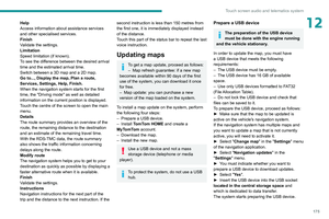 177
177 178
178 179
179 180
180 181
181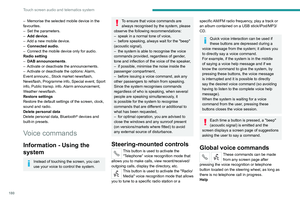 182
182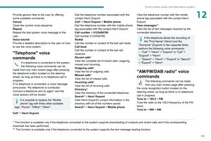 183
183 184
184 185
185 186
186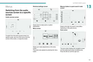 187
187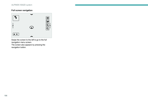 188
188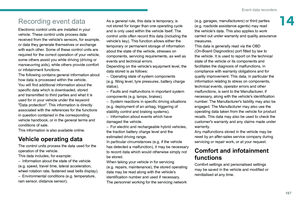 189
189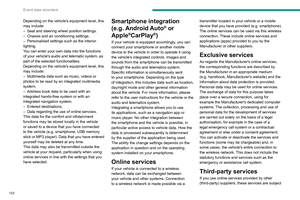 190
190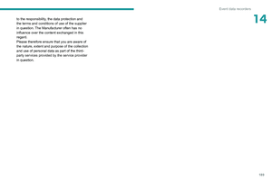 191
191 192
192 193
193 194
194 195
195 196
196 197
197 198
198 199
199 200
200 201
201 202
202 203
203 204
204 205
205 206
206 207
207 208
208 209
209 210
210 211
211