2021 CHRYSLER 300 lock
[x] Cancel search: lockPage 132 of 268
130 MULTIMEDIA
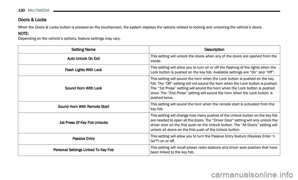
Doors & Locks
When the Doors & Locks button is pressed on the touchscreen, the system displays the options related to locking and unlocking the vehicle’s doors.
NOTE:
Depending on the vehicle’s options, feature settings may vary.
Setting Name Description
Auto Unlock On ExitThis setting will unlock the doors when any of the doors are opened from the
i
n
side.
Flash Lights With Lock This setting will allow you to turn on or off the flashing of the lights when the
Loc
k
button is pushed on the key fob. Available settings are “On” and “Off”.
Sound Horn With Lock This setting will sound the horn when the Lock button is pushed on the key
f
ob
. The “Off” setting will not sound the horn when the Lock button is pushed.
The “1st Press” setting will sound the horn when the Lock button is pushed
once. The “2nd Press” setting will sound the horn when the Lock button is
pushed twice.
Sound Horn With Remote Start This setting will sound the horn when the remote start is activated from the
ke
y fob.
1st Press Of Key Fob Unlocks This setting will change how many pushes of the Unlock button on the key fob
a
r
e needed to open all the doors. The “Driver Door” setting will only unlock the
driver door on the first push on the Unlock button. The “All Doors” setting will
unlock all doors on the first push of the Unlock button.
Passive Entry This setting will allow you to turn the Passive Entry feature (Keyless Enter ‘n
G
o™
) on or off.
Personal Settings Linked To Key Fob This setting will recall preset radio stations and driver seat position that have
b
e
en linked to the key fob.
Page 139 of 268
137
(Continued)
SAFETY
SAFETY FEATURES
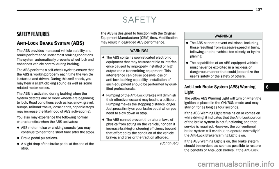
ANTI-LOCK BRAKE SYSTEM (ABS)
The ABS provides increased vehicle stability and
brake performance under most braking conditions.
The system automatically prevents wheel lock and
enhances vehicle control during braking.
The ABS performs a self-check cycle to ensure that
th
e ABS is working properly each time the vehicle
is started and driven. During this self-check, you
may hear a slight clicking sound as well as some
related motor noises.
The ABS is activated during braking when the
s y
stem detects one or more wheels are beginning
to lock. Road conditions such as ice, snow, gravel,
bumps, railroad tracks, loose debris, or panic stops
may increase the likelihood of ABS activation(s).
You also may experience the following normal
c h
aracteristics when the ABS activates:
ABS motor noise or clicking sounds (you may
continue to hear for a short time after the stop).
Brake pedal pulsations.
A slight drop of the brake pedal at the end of the
stop. The ABS is designed to function with the Original
E
q
uipment Manufacturer (OEM) tires. Modification
may result in degraded ABS performance.
Anti-Lock Brake System (ABS) Warning
Light
The yellow ABS Warning Light will turn on when the
ignition is placed in the ON/RUN mode and may
stay on for as long as four seconds.
If the ABS Warning Light remains on or comes on
w h
ile driving, it indicates that the Anti-Lock portion
of the brake system is not functioning and that
service is required. However, the conventional
brake system will continue to operate normally if
the Anti-Lock Brake Warning Light is on.
If the ABS Warning Light is on, the brake system
s h
ould be serviced as soon as possible to restore
the benefits of Anti-Lock Brakes. If the Anti-Lock
WARNING!
The ABS contains sophisticated electronic
equipment that may be susceptible to interfer -
ence caused by improperly installed or high
out
put radio transmitting equipment. This
interference can cause possible loss of
anti-lock braking capability. Installation of
such equipment should be performed by qual -
ified professionals.
Pumping of the Anti-Lock Brakes will diminish
their effectiveness and may lead to a collision.
Pumping makes the stopping distance longer.
Just press firmly on your brake pedal when you
need to slow down or stop.
The ABS cannot prevent the natural laws of
physics from acting on the vehicle, nor can it
increase braking or steering efficiency beyond
that afforded by the condition of the vehicle
brakes and tires or the traction afforded.
The ABS cannot prevent collisions, including
those resulting from excessive speed in turns,
following another vehicle too closely, or hydro -
planing.
The capabilities of an ABS equipped vehicle
must never be exploited in a reckless or
dangerous manner that could jeopardize the
user’s safety or the safety of others.
WARNING!
6
Page 140 of 268
138 SAFETY
Brake Warning Light does not come on when the
ignition is placed in the ON/RUN mode, have the
light repaired as soon as possible.
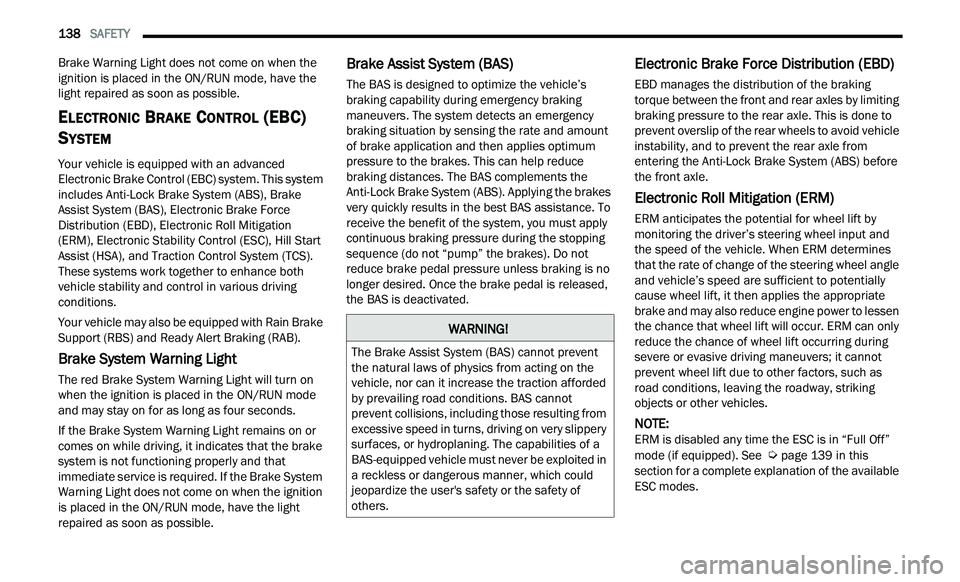
ELECTRONIC BRAKE CONTROL (EBC)
S
YSTEM
Your vehicle is equipped with an advanced
Electronic Brake Control (EBC) system. This system
includes Anti-Lock Brake System (ABS), Brake
Assist System (BAS), Electronic Brake Force
Distribution (EBD), Electronic Roll Mitigation
(ERM), Electronic Stability Control (ESC), Hill Start
Assist (HSA), and Traction Control System (TCS).
These systems work together to enhance both
vehicle stability and control in various driving
conditions.
Your vehicle may also be equipped with Rain Brake
S u
pport (RBS) and Ready Alert Braking (RAB).
Brake System Warning Light
The red Brake System Warning Light will turn on
when the ignition is placed in the ON/RUN mode
and may stay on for as long as four seconds.
If the Brake System Warning Light remains on or
com
es on while driving, it indicates that the brake
system is not functioning properly and that
immediate service is required. If the Brake System
Warning Light does not come on when the ignition
is placed in the ON/RUN mode, have the light
repaired as soon as possible.
Brake Assist System (BAS)
The BAS is designed to optimize the vehicle’s
braking capability during emergency braking
maneuvers. The system detects an emergency
braking situation by sensing the rate and amount
of brake application and then applies optimum
pressure to the brakes. This can help reduce
braking distances. The BAS complements the
Anti-Lock Brake System (ABS). Applying the brakes
very quickly results in the best BAS assistance. To
receive the benefit of the system, you must apply
continuous braking pressure during the stopping
sequence (do not “pump” the brakes). Do not
reduce brake pedal pressure unless braking is no
longer desired. Once the brake pedal is released,
the BAS is deactivated.
Electronic Brake Force Distribution (EBD)
EBD manages the distribution of the braking
torque between the front and rear axles by limiting
braking pressure to the rear axle. This is done to
prevent overslip of the rear wheels to avoid vehicle
instability, and to prevent the rear axle from
entering the Anti-Lock Brake System (ABS) before
the front axle.
Electronic Roll Mitigation (ERM)
ERM anticipates the potential for wheel lift by
monitoring the driver’s steering wheel input and
the speed of the vehicle. When ERM determines
that the rate of change of the steering wheel angle
and vehicle’s speed are sufficient to potentially
cause wheel lift, it then applies the appropriate
brake and may also reduce engine power to lessen
the chance that wheel lift will occur. ERM can only
reduce the chance of wheel lift occurring during
severe or evasive driving maneuvers; it cannot
prevent wheel lift due to other factors, such as
road conditions, leaving the roadway, striking
objects or other vehicles.
NOTE:
ERM is disabled any time the ESC is in “Full Off”
m od
e (if equipped). See Ú page 139 in this
section for a complete explanation of the available
E S
C modes.
WARNING!
The Brake Assist System (BAS) cannot prevent
the natural laws of physics from acting on the
vehicle, nor can it increase the traction afforded
by prevailing road conditions. BAS cannot
prevent collisions, including those resulting from
excessive speed in turns, driving on very slippery
surfaces, or hydroplaning. The capabilities of a
BAS-equipped vehicle must never be exploited in
a reckless or dangerous manner, which could
jeopardize the user's safety or the safety of
others.
Page 145 of 268

SAFETY 143
BSM Warning Light
The BSM detection zone covers approximately one
la
ne width on both sides of the vehicle 12 ft
( 3
.8 m). The zone length starts at the outside
r e
arview mirror and extends approximately 10 ft
( 3
m) beyond the rear fascia/bumper of the
v e
hicle. The BSM system monitors the detection
zones on both sides of the vehicle when the vehicle
speed reaches approximately 6 mph (10 km/h) or
h i
gher and will alert the driver of vehicles in these
areas.
NOTE:
The BSM system DOES NOT alert the driver
about rapidly approaching vehicles that are
outside the detection zones.
The BSM system detection zone DOES NOT
change if your vehicle is towing a trailer. There -
fore, visually verify the adjacent lane is clear for
b ot
h your vehicle and trailer before making a lane change. If the trailer or other object (i.e.,
bicycle, sports equipment) extends beyond the
side of your vehicle, this may result in the BSM
warning light randomly alerting on the trailer or
even remaining illuminated the entire time the
vehicle is in a forward gear
Ú page 122.
The Blind Spot Monitoring (BSM) system may
experience drop outs (blinking on and off) of the
side mirror warning indicator lamps when a
motorcycle or any small object remains at the
side of the vehicle for extended periods of time
(more than a couple of seconds).
The BSM system can become blocked if snow, ice,
mu
d, or other road contaminations accumulate on
the rear fascia/bumper where the radar sensors
are located. The system may also detect blockage
if the vehicle is operated in areas with extremely
low radar returns such as a desert or parallel to a
large elevation drop. If blockage is detected, a
“Blind Spot Temporarily Unavailable, Wipe Rear
Corners” message will display in the cluster, both
mirror lights will illuminate, and BSM and RCP
alerts will not occur. This is normal operation. The
system will automatically recover and resume
function when the condition clears. To minimize
system blockage, do not block the area of the rear
fascia/bumper where the radar sensors are
located with foreign objects (bumper stickers,
bicycle racks, etc.) and keep it clear of road
contaminations.
Sensor Location (Driver Side Shown)
The BSM system notifies the driver of objects in the
d e
tection zones by illuminating the BSM warning
light located in the outside mirrors in addition to
sounding an audible (chime) alert and reducing the
radio volume if the corresponding turn signal is
activated
Ú page 146.
The BSM system monitors the detection zone from
t h
ree different entry points (side, rear, front) while
driving to see if an alert is necessary. The BSM
system will issue an alert during these types of
zone entries.
6
Page 147 of 268

SAFETY 145
The BSM system will not alert you of objects that
are traveling in the opposite direction of the vehicle
in adjacent lanes
Ú page 254.
Opposing Traffic
Rear Cross Path (RCP) Detection — If
Equipped
RCP is intended to aid the driver when backing out
of parking spaces where their vision of oncoming
vehicles may be blocked. Proceed slowly and
cautiously out of the parking space until the rear
end of the vehicle is exposed. The RCP system will
then have a clear view of the cross traffic and if an
oncoming vehicle is detected, alert the driver.
RCP Detection Zones
RCP monitors the rear detection zones on both
si
des of the vehicle, for objects that are moving
toward the side of the vehicle with a minimum
speed of approximately 3 mph (5 km/h), to objects
m ov
ing a maximum of approximately 20 mph
( 3
2 km/h), such as in parking lot situations. When RCP is on and the vehicle is in REVERSE, the
d
r
iver is alerted using both the visual and audible
alarms, including reducing the radio volume.
NOTE:
In a parking lot situation, oncoming vehicles can be
b l
ocked by vehicles parked on either side. If the
sensors are blocked by other structures or
vehicles, the system will not be able to alert the
driver.
WARNING!
The Blind Spot Monitoring system is only an aid
to help detect objects in the blind spot zones.
The BSM system is not designed to detect
pedestrians, bicyclists, or animals. Even if your
vehicle is equipped with the BSM system, always
check your vehicle’s mirrors, glance over your
shoulder, and use your turn signal before
changing lanes. Failure to do so can result in
serious injury or death.
WARNING!
Rear Cross Path Detection (RCP) is not a backup
aid system. It is intended to be used to help a
driver detect an oncoming vehicle in a parking
lot situation. Drivers must be careful when
backing up, even when using RCP. Always check
carefully behind your vehicle, look behind you,
and be sure to check for pedestrians, animals,
other vehicles, obstructions, and blind spots
before backing up. Failure to do so can result in
serious injury or death.
6
Page 155 of 268
SAFETY 153
(Continued)
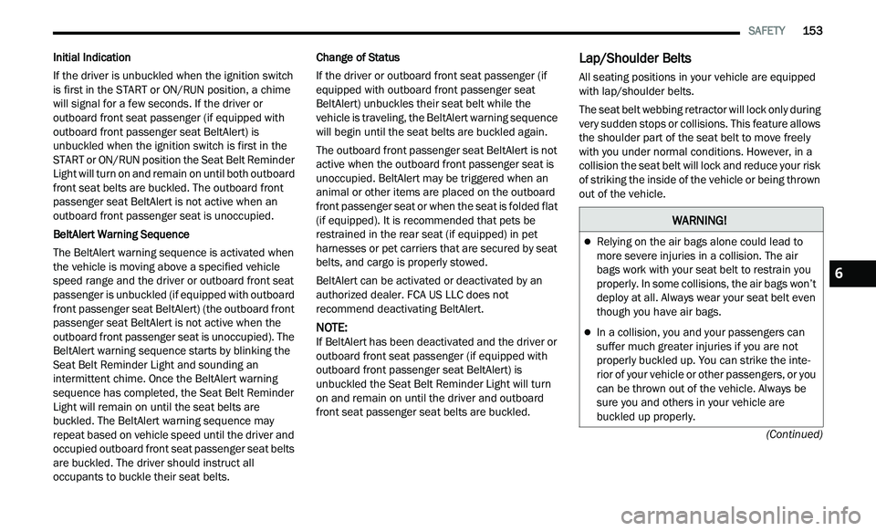
Initial Indication
If the driver is unbuckled when the ignition switch
i s
first in the START or ON/RUN position, a chime
will signal for a few seconds. If the driver or
outboard front seat passenger (if equipped with
outboard front passenger seat BeltAlert) is
unbuckled when the ignition switch is first in the
START or ON/RUN position the Seat Belt Reminder
Light will turn on and remain on until both outboard
front seat belts are buckled. The outboard front
passenger seat BeltAlert is not active when an
outboard front passenger seat is unoccupied.
BeltAlert Warning Sequence
The BeltAlert warning sequence is activated when
t h
e vehicle is moving above a specified vehicle
speed range and the driver or outboard front seat
passenger is unbuckled (if equipped with outboard
front passenger seat BeltAlert) (the outboard front
passenger seat BeltAlert is not active when the
outboard front passenger seat is unoccupied). The
BeltAlert warning sequence starts by blinking the
Seat Belt Reminder Light and sounding an
intermittent chime. Once the BeltAlert warning
sequence has completed, the Seat Belt Reminder
Light will remain on until the seat belts are
buckled. The BeltAlert warning sequence may
repeat based on vehicle speed until the driver and
occupied outboard front seat passenger seat belts
are buckled. The driver should instruct all
occupants to buckle their seat belts. Change of Status
If the driver or outboard front seat passenger (if
e
q
uipped with outboard front passenger seat
BeltAlert) unbuckles their seat belt while the
vehicle is traveling, the BeltAlert warning sequence
will begin until the seat belts are buckled again.
The outboard front passenger seat BeltAlert is not
a c
tive when the outboard front passenger seat is
unoccupied. BeltAlert may be triggered when an
animal or other items are placed on the outboard
front passenger seat or when the seat is folded flat
(if equipped). It is recommended that pets be
restrained in the rear seat (if equipped) in pet
harnesses or pet carriers that are secured by seat
belts, and cargo is properly stowed.
BeltAlert can be activated or deactivated by an
a u
thorized dealer. FCA US LLC does not
recommend deactivating BeltAlert.
NOTE:
If BeltAlert has been deactivated and the driver or
ou t
board front seat passenger (if equipped with
outboard front passenger seat BeltAlert) is
unbuckled the Seat Belt Reminder Light will turn
on and remain on until the driver and outboard
front seat passenger seat belts are buckled.
Lap/Shoulder Belts
All seating positions in your vehicle are equipped
with lap/shoulder belts.
The seat belt webbing retractor will lock only during
ve
ry sudden stops or collisions. This feature allows
the shoulder part of the seat belt to move freely
with you under normal conditions. However, in a
collision the seat belt will lock and reduce your risk
of striking the inside of the vehicle or being thrown
out of the vehicle.
WARNING!
Relying on the air bags alone could lead to
more severe injuries in a collision. The air
bags work with your seat belt to restrain you
properly. In some collisions, the air bags won’t
deploy at all. Always wear your seat belt even
though you have air bags.
In a collision, you and your passengers can
suffer much greater injuries if you are not
properly buckled up. You can strike the inte -
rior of your vehicle or other passengers, or you
c a
n be thrown out of the vehicle. Always be
sure you and others in your vehicle are
buckled up properly.
6
Page 158 of 268
156 SAFETY
Adjustable Upper Shoulder Belt Anchorage
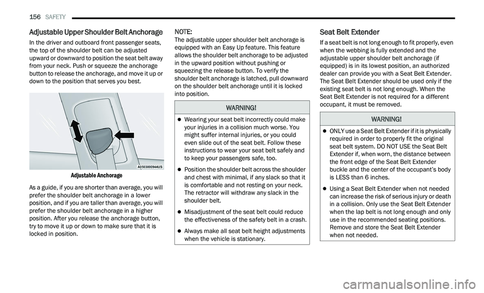
In the driver and outboard front passenger seats,
the top of the shoulder belt can be adjusted
upward or downward to position the seat belt away
from your neck. Push or squeeze the anchorage
button to release the anchorage, and move it up or
down to the position that serves you best.
Adjustable Anchorage
As a guide, if you are shorter than average, you will
p r
efer the shoulder belt anchorage in a lower
position, and if you are taller than average, you will
prefer the shoulder belt anchorage in a higher
position. After you release the anchorage button,
try to move it up or down to make sure that it is
locked in position.
NOTE:
The adjustable upper shoulder belt anchorage is
e q
uipped with an Easy Up feature. This feature
allows the shoulder belt anchorage to be adjusted
in the upward position without pushing or
squeezing the release button. To verify the
shoulder belt anchorage is latched, pull downward
on the shoulder belt anchorage until it is locked
into position.Seat Belt Extender
If a seat belt is not long enough to fit properly, even
when the webbing is fully extended and the
adjustable upper shoulder belt anchorage (if
equipped) is in its lowest position, an authorized
dealer can provide you with a Seat Belt Extender.
The Seat Belt Extender should be used only if the
existing seat belt is not long enough. When the
Seat Belt Extender is not required for a different
occupant, it must be removed.
WARNING!
Wearing your seat belt incorrectly could make
your injuries in a collision much worse. You
might suffer internal injuries, or you could
even slide out of the seat belt. Follow these
instructions to wear your seat belt safely and
to keep your passengers safe, too.
Position the shoulder belt across the shoulder
and chest with minimal, if any slack so that it
is comfortable and not resting on your neck.
The retractor will withdraw any slack in the
shoulder belt.
Misadjustment of the seat belt could reduce
the effectiveness of the safety belt in a crash.
Always make all seat belt height adjustments
when the vehicle is stationary.
WARNING!
ONLY use a Seat Belt Extender if it is physically
required in order to properly fit the original
seat belt system. DO NOT USE the Seat Belt
Extender if, when worn, the distance between
the front edge of the Seat Belt Extender
buckle and the center of the occupant’s body
is LESS than 6 inches.
Using a Seat Belt Extender when not needed
can increase the risk of serious injury or death
in a collision. Only use the Seat Belt Extender
when the lap belt is not long enough and only
use in the recommended seating positions.
Remove and store the Seat Belt Extender
when not needed.
Page 159 of 268
SAFETY 157
Seat Belts And Pregnant Women
Seat Belts and Pregnant Women
Seat belts must be worn by all occupants including
pr
egnant women: the risk of injury in the event of
an accident is reduced for the mother and the
unborn child if they are wearing a seat belt.
Position the lap belt snug and low below the
ab
domen and across the strong bones of the hips.
Place the shoulder belt across the chest and away
from the neck. Never place the shoulder belt
behind the back or under the arm.
Seat Belt Pretensioner
The front outboard seat belt system is equipped
with pretensioning devices that are designed to
remove slack from the seat belt in the event of a
collision. These devices may improve the
performance of the seat belt by removing slack from the seat belt early in a collision. Pretensioners
work for all size occupants, including those in child
restraints.
NOTE:
These devices are not a substitute for proper seat
b e
lt placement by the occupant. The seat belt still
must be worn snugly and positioned properly.
The pretensioners are triggered by the Occupant
R e
straint Controller (ORC). Like the air bags, the
pretensioners are single use items. A deployed
pretensioner or a deployed air bag must be
replaced immediately.
Energy Management Feature
The front outboard seat belt system is equipped
with an Energy Management feature that may help
further reduce the risk of injury in the event of a
collision. The seat belt system has a retractor
assembly that is designed to release webbing in a
controlled manner.
Switchable Automatic Locking Retractors
(ALR)
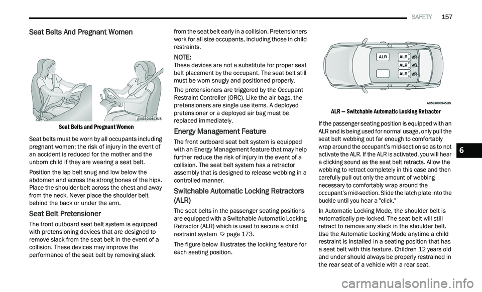
The seat belts in the passenger seating positions
are equipped with a Switchable Automatic Locking
Retractor (ALR) which is used to secure a child
restraint system
Ú page 173.
The figure below illustrates the locking feature for
e a
ch seating position.
ALR — Switchable Automatic Locking Retractor
If the passenger seating position is equipped with an
A L
R and is being used for normal usage, only pull the
seat belt webbing out far enough to comfortably
wrap around the occupant’s mid-section so as to not
activate the ALR. If the ALR is activated, you will hear
a clicking sound as the seat belt retracts. Allow the
webbing to retract completely in this case and then
carefully pull out only the amount of webbing
necessary to comfortably wrap around the
occupant’s mid-section. Slide the latch plate into the
buckle until you hear a "click."
In Automatic Locking Mode, the shoulder belt is
a u
tomatically pre-locked. The seat belt will still
retract to remove any slack in the shoulder belt.
Use the Automatic Locking Mode anytime a child
restraint is installed in a seating position that has
a seat belt with this feature. Children 12 years old
and under should always be properly restrained in
the rear seat of a vehicle with a rear seat.
6