2021 CHRYSLER 300 lock
[x] Cancel search: lockPage 25 of 268
GETTING TO KNOW YOUR VEHICLE 23
CHILD-PROTECTION DOOR LOCK
S
YSTEM — REAR DOORS
To provide a safer environment for small children
riding in the rear seats, the rear doors are
equipped with Child-Protection Door Lock system.
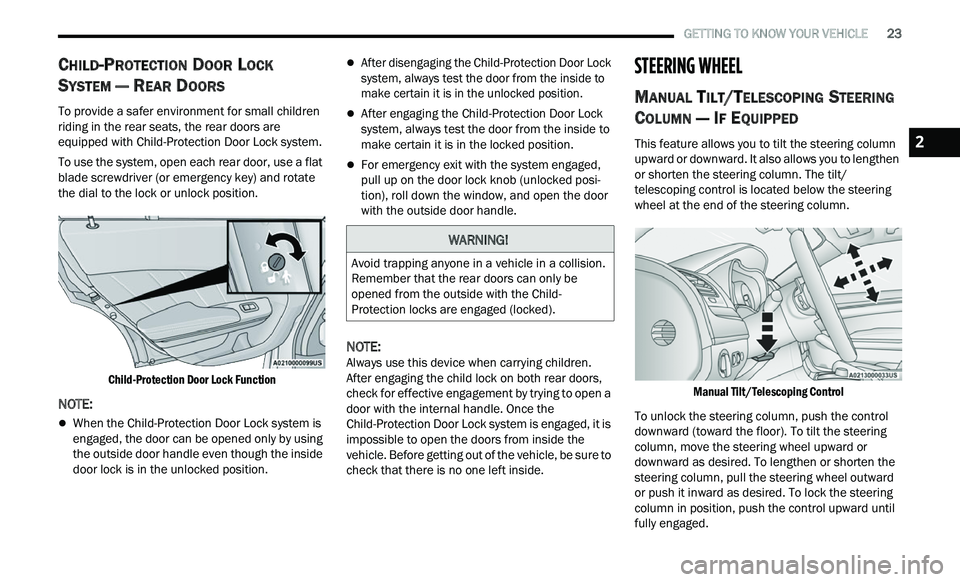
To use the system, open each rear door, use a flat
b l
ade screwdriver (or emergency key) and rotate
the dial to the lock or unlock position.
Child-Protection Door Lock Function
NOTE:
When the Child-Protection Door Lock system is
engaged, the door can be opened only by using
the outside door handle even though the inside
door lock is in the unlocked position.
After disengaging the Child-Protection Door Lock
system, always test the door from the inside to
make certain it is in the unlocked position.
After engaging the Child-Protection Door Lock
system, always test the door from the inside to
make certain it is in the locked position.
For emergency exit with the system engaged,
pull up on the door lock knob (unlocked posi -
tion), roll down the window, and open the door
w i
th the outside door handle.
NOTE:
Always use this device when carrying children.
A f
ter engaging the child lock on both rear doors,
check for effective engagement by trying to open a
door with the internal handle. Once the
Child-Protection Door Lock system is engaged, it is
impossible to open the doors from inside the
vehicle. Before getting out of the vehicle, be sure to
check that there is no one left inside.
STEERING WHEEL
MANUAL TILT/TELESCOPING STEERING
C
OLUMN — IF EQUIPPED
This feature allows you to tilt the steering column
upward or downward. It also allows you to lengthen
or shorten the steering column. The tilt/
telescoping control is located below the steering
wheel at the end of the steering column.
Manual Tilt/Telescoping Control
To unlock the steering column, push the control
dow
nward (toward the floor). To tilt the steering
column, move the steering wheel upward or
downward as desired. To lengthen or shorten the
steering column, pull the steering wheel outward
or push it inward as desired. To lock the steering
column in position, push the control upward until
fully engaged.
WARNING!
Avoid trapping anyone in a vehicle in a collision.
Remember that the rear doors can only be
opened from the outside with the Child-
Protection locks are engaged (locked).
2
Page 26 of 268
24 GETTING TO KNOW YOUR VEHICLE
POWER TILT/TELESCOPING STEERING
C
OLUMN — IF EQUIPPED
This feature allows you to tilt the steering column
upward or downward. It also allows you to lengthen
or shorten the steering column. The power tilt/
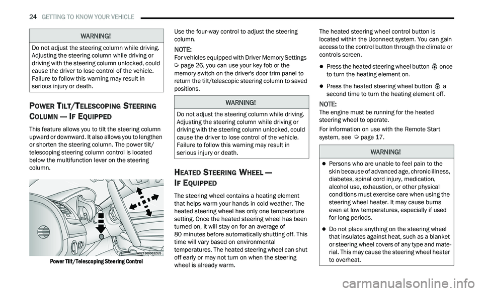
telescoping steering column control is located
below the multifunction lever on the steering
column.
Power Tilt/Telescoping Steering Control
Use the four-way control to adjust the steering
c
ol
umn.
NOTE:
For vehicles equipped with Driver Memory Settings
Ú page 26, you can use your key fob or the
memory switch on the driver's door trim panel to
r e
turn the tilt/telescopic steering column to saved
positions.
HEATED STEERING WHEEL —
I
F EQUIPPED
The steering wheel contains a heating element
that helps warm your hands in cold weather. The
heated steering wheel has only one temperature
setting. Once the heated steering wheel has been
turned on, it will stay on for an average of
80 minutes before automatically shutting off. This
t i
me will vary based on environmental
temperatures. The heated steering wheel can shut
off early or may not turn on when the steering
wheel is already warm. The heated steering wheel control button is
l
oc
ated within the Uconnect system. You can gain
access to the control button through the climate or
controls screen.
Press the heated steering wheel button once
to turn the heating element on.
Press the heated steering wheel button a
second time to turn the heating element off.
NOTE:
The engine must be running for the heated
s t
eering wheel to operate.
For information on use with the Remote Start
sy
stem, see Ú page 17.
WARNING!
Do not adjust the steering column while driving.
Adjusting the steering column while driving or
driving with the steering column unlocked, could
cause the driver to lose control of the vehicle.
Failure to follow this warning may result in
serious injury or death.
WARNING!
Do not adjust the steering column while driving.
Adjusting the steering column while driving or
driving with the steering column unlocked, could
cause the driver to lose control of the vehicle.
Failure to follow this warning may result in
serious injury or death.
WARNING!
Persons who are unable to feel pain to the
skin because of advanced age, chronic illness,
diabetes, spinal cord injury, medication,
alcohol use, exhaustion, or other physical
conditions must exercise care when using the
steering wheel heater. It may cause burns
even at low temperatures, especially if used
for long periods.
Do not place anything on the steering wheel
that insulates against heat, such as a blanket
or steering wheel covers of any type and mate
-
rial. This may cause the steering wheel heater
t o
overheat.
Page 29 of 268

GETTING TO KNOW YOUR VEHICLE 27
(Continued)
LINKING AND UNLINKING THE KEY FOB
T
O MEMORY
Your key fobs can be programmed to recall one of
two saved memory profiles.
NOTE:
Before programming your key fobs you must select
t h
e “Memory Linked To Fob” feature through the
Uconnect system
Ú page 122.
To program your key fobs, perform the following:
1. P lace the vehicle’s ignition in the OFF
p
osition.
2. Select a desired memory profile, 1 or 2.
3
. O nce the profile has been recalled, push and
r
elease the set (S) button on the memory
switch.
4. W ithin five seconds, push and release button
(
1) or (2) accordingly. “Memory Profile Set”
(1 or 2) will display in the instrument cluster.
5. P ush and release the lock button on the key
f
ob within 10 seconds.
NOTE:
Your key fob can be unlinked from your memory
s e
ttings by pushing the set (S) button, followed by
pushing the unlock button on the key fob within
10 seconds.
MEMORY POSITION RECALL
NOTE:
If a recall is attempted when the vehicle is not in
P A
RK, a message will be displayed in the
instrument cluster display.
To recall the memory settings for driver one or two,
p u
sh the desired memory button number (1 or 2)
or the unlock button on the key fob linked to the
desired memory position.
A recall can be canceled by pushing any of the
me
mory buttons (S, 1, or 2) during a recall. When
a recall is canceled, the driver seat will stop
moving. A delay of one second will occur before
another recall can be selected.
SEATS
Seats are a part of the Occupant Restraint system
of the vehicle.
MANUAL ADJUSTMENT (REAR SEATS)
Folding Rear Seat
The rear seatbacks can be folded forward to
provide an additional storage area. To fold the rear
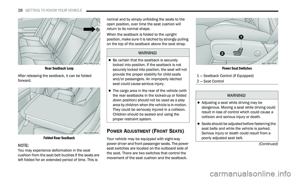
seatback, pull on the loops located on the upper
seatback.
NOTE:
These loops can be tucked away when not in use.
WARNING!
It is dangerous to ride in a cargo area, inside
or outside of a vehicle. In a collision, people
riding in these areas are more likely to be seri -
ously injured or killed.
Do not allow people to ride in any area of your
vehicle that is not equipped with seats and
seat belts. In a collision, people riding in these
areas are more likely to be seriously injured or
killed.
Be sure everyone in your vehicle is in a seat
and using a seat belt properly.
WARNING!
2
Page 30 of 268
28 GETTING TO KNOW YOUR VEHICLE
(Continued)
Rear Seatback Loop
After releasing the seatback, it can be folded
for
ward.
Folded Rear Seatback
NOTE:
You may experience deformation in the seat
c u
shion from the seat belt buckles if the seats are
left folded for an extended period of time. This is normal and by simply unfolding the seats to the
open position, over time the seat cushion will
return to its normal shape.
When the seatback is folded to the upright
p
os
ition, make sure it is latched by strongly pulling
on the top of the seatback above the seat strap.
POWER ADJUSTMENT (FRONT SEATS)
Your vehicle may be equipped with eight-way
power driver and front passenger seats. The power
seat switches are located on the outboard side of
the seat. There are two switches that control the
movement of the seat cushion and the seatback.
Power Seat Switches
WARNING!
Be certain that the seatback is securely
locked into position. If the seatback is not
securely locked into position, the seat will not
provide the proper stability for child seats
and/or passengers. An improperly latched
seat could cause serious injury.
The cargo area in the rear of the vehicle (with
the rear seatbacks in the locked-up or folded
down position) should not be used as a play
area by children when the vehicle is in motion.
They could be seriously injured in a collision.
Children should be seated and using the
proper restraint system.
1 — Seatback Control (If Equipped)
2 — Seat Control
WARNING!
Adjusting a seat while driving may be
dangerous. Moving a seat while driving could
result in loss of control which could cause a
collision and serious injury or death.
Seats should be adjusted before fastening the
seat belts and while the vehicle is parked.
Serious injury or death could result from a
poorly adjusted seat belt.
Page 36 of 268

34 GETTING TO KNOW YOUR VEHICLE
MIRRORS
INSIDE REARVIEW MIRROR
Automatic Dimming Mirror
The rearview mirror can be adjusted up, down, left,
and right. The mirror should be adjusted to center
on the view through the rear window.
This mirror automatically adjusts for headlight
gl
are from vehicles behind you.
NOTE:
The Automatic Dimming Mirror feature is disabled
w h
en the vehicle is in REVERSE to improve the
driver’s rear view.
The Automatic Dimming feature can be turned on
or
off through the Uconnect system Ú page 122.
Automatic Dimming Mirror
ILLUMINATED VANITY MIRRORS
To access an illuminated vanity mirror, flip down
one of the visors and lift the cover.
Illuminated Vanity Mirror
Sun Visor “Slide-On-Rod” Feature
The sun visor “Slide-On-Rod” feature allows for
additional flexibility in positioning the sun visor to
block out the sun.
1. Fold down the sun visor.
2
. U nclip the visor from the corner clip.
3
. P ivot the sun visor toward the side window.
4
. E xtend the sun visor for additional sun
b
lockage.
Slide-On-Rod Feature
NOTE:
The sun visor can also be extended while the sun
v i
sor is against the windshield for additional sun
blockage through the front of the vehicle.
CAUTION!
To avoid damage to the mirror during cleaning,
never spray any cleaning solution directly onto
the mirror. Apply the solution onto a clean cloth
and wipe the mirror clean.
Page 38 of 268
36 GETTING TO KNOW YOUR VEHICLE
POWER FOLDING OUTSIDE MIRRORS —
I
F EQUIPPED
If equipped with power folding mirrors, they can be
electrically folded rearward and unfolded into the
drive position.
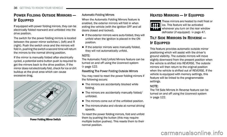
The switch for the power folding mirrors is located
b e
tween the power mirror switches L (left) and R
(right). Push the switch once and the mirrors will
fold in, pushing the switch a second time will return
the mirrors to the normal driving position.
If the mirror is manually folded after electrically
c y
cled, a potential extra button push is required to
get the mirrors back to the drive position. If the
mirror does not electrically fold, check for ice or dirt
buildup at the pivot area which can cause
excessive drag.
Power Folding Mirror Switch
Automatic Folding Mirrors
When the Automatic Folding Mirrors feature is
e
n
abled, the exterior mirrors will fold in when
exiting the vehicle (with the ignition OFF and all
doors closed and locked).
If the exterior mirrors were auto-folded, they will
unfold when the ignition is placed in the ON
position.
If the exterior mirrors were manually folded,
they will not automatically unfold.
NOTE:
The Automatic Fold/Unfold Mirrors feature can be
t u
rned on and off using the Uconnect system
Ú page 122.
Resetting The Power Folding Outside Mirrors
You may need to reset the power folding mirrors if
t h
e following occurs:
The mirrors are accidentally blocked while
folding.
The mirrors are accidentally manually folded/
unfolded.
The mirrors come out of the unfolded position.
The mirrors shake and vibrate at normal driving
speeds.
To reset the power folding mirrors, fold and unfold
th
em by pushing the button (this may require
multiple button pushes). This resets them to their
normal position.
HEATED MIRRORS — IF EQUIPPED
These mirrors are heated to melt frost or
ice. This feature will be activated
w h
enever you turn on the rear window
defroster (if equipped)
Ú page 47.
TILT SIDE MIRRORS IN REVERSE —
I
F EQUIPPED
This feature provides automatic outside mirror
positioning which will assist with the driver’s
ground visibility. The outside mirrors will move
slightly downward from the present position when
the vehicle is shifted into REVERSE. The outside
mirrors will then return to the original position
when the vehicle is shifted out of REVERSE. If the
vehicle is equipped with memory settings, this
feature will be linked to the programmable
settings.
NOTE:
The Tilt Side Mirrors In Reverse feature can be
t u
rned on and off using the Uconnect system
Ú page 122.
Page 42 of 268
40 GETTING TO KNOW YOUR VEHICLE
EXTERIOR LIGHTS
HEADLIGHT SWITCH
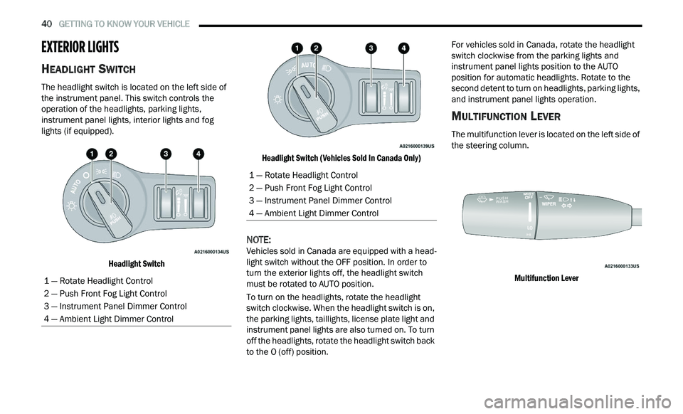
The headlight switch is located on the left side of
the instrument panel. This switch controls the
operation of the headlights, parking lights,
instrument panel lights, interior lights and fog
lights (if equipped).
Headlight Switch Headlight Switch (Vehicles Sold In Canada Only)
NOTE:
Vehicles sold in Canada are equipped with a head -
light switch without the OFF position. In order to
t u
rn the exterior lights off, the headlight switch
must be rotated to AUTO position.
To turn on the headlights, rotate the headlight
s w
itch clockwise. When the headlight switch is on,
the parking lights, taillights, license plate light and
instrument panel lights are also turned on. To turn
off the headlights, rotate the headlight switch back
to the O (off) position. For vehicles sold in Canada, rotate the headlight
sw
itch clockwise from the parking lights and
instrument panel lights position to the AUTO
position for automatic headlights. Rotate to the
second detent to turn on headlights, parking lights,
and instrument panel lights operation.
MULTIFUNCTION LEVER
The multifunction lever is located on the left side of
the steering column.
Multifunction Lever
1 — Rotate Headlight Control
2 — Push Front Fog Light Control
3 — Instrument Panel Dimmer Control
4 — Ambient Light Dimmer Control
1 — Rotate Headlight Control
2 — Push Front Fog Light Control
3 — Instrument Panel Dimmer Control
4 — Ambient Light Dimmer Control
Page 43 of 268
GETTING TO KNOW YOUR VEHICLE 41
DAYTIME RUNNING LIGHTS (DRLS)
The Daytime Running Lights will turn on when the
engine is started and will remain on unless the
headlights are turned to the on position, the
parking brake is applied, or the ignition is placed in
the OFF position.
NOTE:
For vehicles sold in Canada, the Daytime
Running Lights will automatically deactivate
when the front fog lights are turned on.
If allowed by law in the country in which the
vehicle was purchased, the Daytime Running
Lights can be turned on and off using the
Uconnect system
Ú page 122.
On some vehicles, the Daytime Running Lights
may deactivate or reduce intensity on one side
of the vehicle (when a turn signal is activated on
that side), or on both sides of the vehicle (when
the hazard warning lights are activated).
HIGH/LOW BEAM SWITCH
Push the multifunction lever toward the instrument
panel to switch the headlights to high beams.
Pulling the multifunction lever back will turn the
low beams on.
AUTOMATIC HIGH BEAM — IF EQUIPPED
The Automatic High Beam Headlamp Control
system provides increased forward lighting at night
by automating high beam control through the use
of a digital camera mounted on the inside rearview
mirror. This camera detects vehicle specific light
and automatically switches from high beams to low
beams until the approaching vehicle is out of view.
NOTE:
The Automatic High Beam Headlamp Control
can be turned on or off by selecting or dese
-
lecting “Auto High Beam” within Uconnect
Se
ttings Ú page 122, as well as turning the
headlight switch to the AUTO position.
Broken, muddy, or obstructed headlights and
taillights of vehicles in the field of view will
cause headlights to remain on longer (closer to
the vehicle). Also, dirt, film, and other obstruc -
tions on the windshield or camera lens will
c a
use the system to function improperly.
If the windshield or Automatic High Beam Head -
lamp Control mirror is replaced, the mirror must
b e
re-aimed to ensure proper performance. See
a local authorized dealer.
FLASH-TO-PASS
You can signal another vehicle with your headlights
by lightly pulling the multifunction lever toward you. This will cause the high beam headlights to turn on,
and remain on, until the lever is released.
AUTOMATIC HEADLIGHTS
This system automatically turns the headlights on
or off according to ambient light levels. To turn the
system on, rotate the headlight switch
counterclockwise to the AUTO position. When the
system is on, the headlight time delay feature is
also on. This means the headlights will stay on for
up to 90 seconds after placing the ignition in the
OFF position. The headlight time delay can be
programmed 0/30/60/90 seconds within
Uconnect Settings
Ú page 122.
To turn the automatic system off, move the
h e
adlight switch out of the AUTO position.
NOTE:
The engine must be running before the headlights
w i
ll come on in the automatic mode.
PARKING LIGHTS
To turn on the parking lights and instrument panel
lights, rotate the headlight switch clockwise. To
turn off the parking lights, rotate the headlight
switch back to the O (off) position.
NOTE:
For vehicles sold in Canada, rotate the headlight
s w
itch to the AUTO position to turn off the parking
lights.
2