2021 ALFA ROMEO STELVIO radio
[x] Cancel search: radioPage 158 of 280
SAFETY
156
disappear from the display and the symbol will
be displayed in the dedicated area of the
instrument cluster display until the next
engine shutdown.
If the driver ignores the warning provided by
the system and does not stop, the message
will continue to remain on the display, along
with the symbol.
NOTE:
In the event of a DAA system failure, an
amber symbol will appear in the instrument
cluster display along with a dedicated
message.
If the ABS system activates, “ABS ACTIVE”
will display in place of the DAA symbol and
will remain active until the ABS system
deactivates.
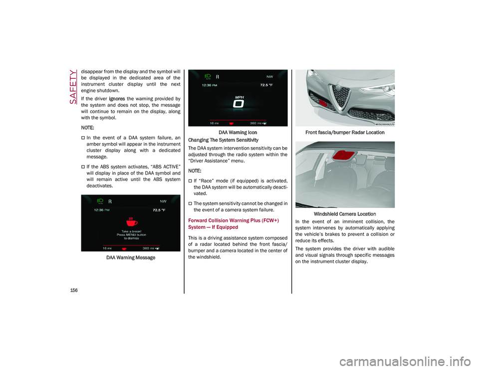
DAA Warning Message DAA Warning Icon
Changing The System Sensitivity
The DAA system intervention sensitivity can be
adjusted through the radio system within the
“Driver Assistance” menu.
NOTE:
If “Race” mode (if equipped) is activated,
the DAA system will be automatically deacti -
vated.
The system sensitivity cannot be changed in
the event of a camera system failure.
Forward Collision Warning Plus (FCW+)
System — If Equipped
This is a driving assistance system composed
of a radar located behind the front fascia/
bumper and a camera located in the center of
the windshield. Front fascia/bumper Radar Location
Windshield Camera Location
In the event of an imminent collision, the
system intervenes by automatically applying
the vehicle’s brakes to prevent a collision or
reduce its effects.
The system provides the driver with audible
and visual signals through specific messages
on the instrument cluster display.
21_GU_OM_EN_USC_t.book Page 156
Page 160 of 280
SAFETY
158
Activation/Deactivation
The Forward Collision Warning system is acti-
vated whenever the engine is started regard -
less of what is shown on the radio system.
Following a deactivation, the system will not
warn the driver about the possible collision
with a preceding vehicle, regardless of the
setting selected in the radio system.
NOTE:
Each time the engine is started, the system is
activated regardless of what setting was
selected when the engine was turned off.
This function is not active at a speed lower
than 4 mph (7 km/h) or higher than 124 mph
(200 km/h).
The system is active:
Each time the engine is started
When feature is selected within the radio
system
When the ignition is in the ON position
When the vehicle speed is between 2 mph
(4 km/h) and 124 mph (200 km/h)
When the front seat belts are fastened
The "Alfa DNA Pro" selector is not in RACE
position (if equipped)
NOTE:
If the seat belts of the front seats are not
correctly fastened, the system will not inter -vene on the braking system (only audible and
visual signals will be provided).
Changing The System Sensitivity
The sensitivity of the system can be changed
through the Information and Entertainment
system menu, choosing from one of the
following three options: "Near", "Medium" or
"Far". Refer to the description in the Informa
-
tion and Entertainment system Supplement
for how to change the settings.
The default setting is "Medium". With this
setting, the system warns the driver of a
possible collision with the vehicle in front
when that vehicle is at a standard distance,
between that of the other two settings.
With the system sensitivity set to "Far", the
system will warn the driver of a possible colli -
sion with the vehicle in front when that vehicle
is at a greater distance, thus providing the
possibility of acting on the brakes more lightly
and gradually. This setting provides the driver
with the maximum possible reaction time to
prevent a potential collision.
With the option set to "Near", the system will
alert the driver of a possible collision with the
vehicle in front when that vehicle is close. This
setting offers the driver a lower reaction time
compared to the "Medium" and "Far" settings,
in the event of a potential collision, but
permits more dynamic driving of the vehicle.
The system sensitivity setting is kept in the
memory when the engine is turned off. System Limited Operation Warning
If a dedicated message is displayed, a condi
-
tion limiting the system operation may have
occurred. The possible reasons of this limita -
tion are something is blocking the camera
view or a fault.
If an obstruction is signaled, clean the area of
the radar on the front fascia/bumper, and the
camera area on the windshield.
If a fault in the system is occurring, it will still
be possible to drive the vehicle normally, but
automatic braking will not be available in the
event of an impending collision.
When the conditions limiting the system func -
tions end, this will go back to normal and
complete operation. Should the fault persist,
contact an authorized dealer.
System Failure Signaling
If the system turns off and a dedicated
message is shown on the display, it means
that there is a fault with the system.
In this case, it is still possible to drive the
vehicle, but you are advised to contact an
authorized dealer as soon as possible.
Radar Indication Not Available
If conditions are such that the radar cannot
detect obstacles correctly, the system is deac -
tivated and a dedicated message appears on
the display. This generally occurs in the event
of poor visibility, such as when it is snowing or
raining heavily.
21_GU_OM_EN_USC_t.book Page 158
Page 161 of 280

159
The function of this system can also be tempo-
rarily reduced due to obstructions such as
mud, dirt or ice on the fascia/bumper. In such
cases, a dedicated message will be shown on
the display and the system will be deactivated.
This message can sometimes appear in condi -
tions of high reflectivity (e.g. tunnels with
reflective tiles or ice or snow). When the condi -
tions limiting the system functions end, it will
go back to normal and complete operation.
In certain cases, this dedicated message
could be displayed when the radar is not
detecting any vehicles or objects within its
view range.
If atmospheric conditions are not the reason
behind this message, check if the sensor is
dirty. It could be necessary to clean or remove
any obstructions in the area.
If the message appears frequently, even in the
absence of atmospheric conditions such as
snow, rain, mud or other obstructions, contact
an authorized dealer for a sensor alignment
check.
In the absence of visible obstructions, manu -
ally removing the decorative cover trim and
cleaning the radar surface could be required.
Have this operation performed at an autho -
rized dealer.
NOTE:
It is recommended that you do not install
devices, accessories or aerodynamic attach
-
ments in front of the sensor or darken it in any
way, as this can compromise the correct func -
tioning of the system.
Frontal Collision Alarm With Active Braking — If
Equipped
If this function is selected, the brakes are
operated to reduce the speed of the vehicle in
the event of potential frontal impact.
This function applies an additional braking
pressure if the braking pressure applied by the
driver does not suffice to prevent potential
frontal impact.
The function is active with speed above 2 mph
(4 km/h).
NOTE:
When using an automatic car wash it is recom -
mended to deactivate the system through the
settings of the radio system. The system may
detect the presence of a car, a wall or another
obstacle and activate.
Driving In Special Conditions
In certain driving conditions, system interven -
tion might be unexpected or delayed. The
driver must therefore be very careful, keeping
control of the vehicle to drive in complete
safety.Driving close to a bend.
The vehicle ahead is leaving a roundabout.
Vehicles with small dimensions and/or not
aligned in the driving lane.
Lane change by other vehicles.
Vehicles traveling at right angles to the
vehicle.
NOTE:
In particularly complex traffic conditions,
the driver can deactivate the system manu -
ally through the Information and Entertain -
ment system.
If the driver depresses the brake pedal fully
or makes an excessive steering maneuver
during system operation, the automatic
braking function may deactivate (e.g. to
allow a possible maneuver to avoid the
obstacle).
The FCW system is automatically deacti -
vated when operating in race mode and a
warning message will be displayed on the
instrument cluster.
21_GU_OM_EN_USC_t.book Page 159
Page 164 of 280
SAFETY
162
will turn off only after the tires are inflated to the
vehicle’s recommended cold placard pressure
value.Insufficient Tire Pressure Indication
If an insufficient pressure value is detected on
one or more tires, the warning light in the
instrument cluster will display alongside the
dedicated messages, the system will highlight
the tire or tires with insufficient pressure
graphically, and an acoustic signal will be
emitted.
In this case, stop the vehicle, check the infla
-
tion pressure of each tire, and inflate the
necessary tire or tires to the correct cold infla -
tion pressure value, shown on the display or in
the dedicated TPMS menu.
TPMS Temporarily Disabled:
TPMS Check Message
When a system fault is detected, the TPMS
Warning Light will flash on and off for 75 seconds,
and then remain on solid. The system fault will
also sound a chime. If the ignition is cycled, this
sequence will repeat, provided that the system
fault still exists. The TPMS Warning Light will turn
off when the fault condition no longer exists. A
system fault can occur due to any of the
following:
Jamming due to electronic devices or
driving next to facilities emitting the same
radio frequencies as the TPMS sensors.
Installing some form of aftermarket window
tinting that affects radio wave signals.
Packed snow or ice around the wheels or
wheel housings.
Using tire chains on the vehicle.
Using wheels/tires not equipped with TPMS
sensors.
After the punctured tire has been repaired
with the original tire sealant contained in the
Tire Kit, the previous condition must be
restored so that the warning light is off
during normal driving.
TPMS Deactivation
The TPMS can be deactivated by replacing all
four wheel and tire assemblies (road tires)
with wheel and tire assemblies that do not
have TPMS sensors, such as when installing
winter wheel and tire assemblies on your
vehicle.
To deactivate the TPMS, first replace all four
wheel and tire assemblies (road tires) with tires
not equipped with Tire Pressure Monitoring
System (TPMS) sensors. Then, drive the vehicle
for 20 minutes above 15 mph (24 km/h). The
TPMS will chime, the TPMS Warning Light will
flash on and off for 75 seconds and then
remain on. The instrument cluster will display
the “SERVICE TPM SYSTEM” message and then
display dashes (--) in place of the pressure
values.
Beginning with the next ignition switch cycle,
the TPMS will no longer chime or display the
“SERVICE TPM SYSTEM” message in the
instrument cluster. Instead, dashes (--) will
remain in place of the pressure values.
CAUTION!
The TPMS has been optimized for the orig -
inal equipment tires and wheels. TPMS
pressures and warning have been estab -
lished for the tire size equipped on your
vehicle. Undesirable system operation or
sensor damage may result when using
replacement equipment that is not of the
same size, type, and/or style. The TPMS
sensor is not designed for use on after -
market wheels and may contribute to a
poor overall system performance or
sensor damage. Customers are encour -
aged to use OEM wheels to assure proper
TPMS feature operation.
Using aftermarket tire sealants may cause
the Tire Pressure Monitoring System
(TPMS) sensor to become inoperable.
After using an aftermarket tire sealant it is
recommended that you take your vehicle
to an authorized dealer to have your
sensor function checked.
After inspecting or adjusting the tire pres -
sure always reinstall the valve stem cap.
This will prevent moisture and dirt from
entering the valve stem, which could
damage the TPMS sensor.
21_GU_OM_EN_USC_t.book Page 162
Page 174 of 280
SAFETY
172
damage by themselves are not good indicators
of whether or not an air bag should have
deployed.
Seat belts are necessary for your protection in
all collisions, and also are needed to help keep
you in position, away from an inflating air bag.
When the Occupant Restraint Controller (ORC)
detects a collision requiring the front air bags,
it signals the inflator units. A large quantity of
non-toxic gas is generated to inflate the front
air bags.
The steering wheel hub trim cover and the
upper passenger side of the instrument panel
separate and fold out of the way as the air
bags inflate to their full size. The front air bags
fully inflate in less time than it takes to blink
your eyes. The front air bags then quickly
deflate while helping to restrain the driver and
front passenger.
Knee Impact Bolsters
The Knee Impact Bolsters help protect the
knees of the driver and front passenger, and
position the front occupants for improved
interaction with the front air bags.
Supplemental Driver And Front Passenger
Knee Air Bags
This vehicle is equipped with a Supplemental
Driver Knee Air Bag mounted in the instrument
panel below the steering column and a
Supplemental Passenger Knee Air Bag
mounted in the instrument panel below the
glove compartment. The Supplemental Knee
Air Bags provide enhanced protection during a
frontal impact by working together with the
seat belts, pretensioners, and front air bags.
Supplemental Side Air Bags
Supplemental Seat-Mounted Side Air Bags
(SABs)
This vehicle is equipped with Supplemental
Seat-Mounted Side Air Bags (SABs).
Supplemental Seat-Mounted Side Air Bags
(SABs) are located in the outboard side of the
front seats. The SABs are marked with “SRS
AIRBAG” or “AIRBAG” on a label or on the seat
trim on the outboard side of the seats.
The SABs may help to reduce the risk of occu-
pant injury during certain side impacts, in addi-
tion to the injury reduction potential provided
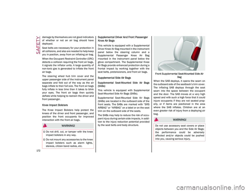
by the seat belts and body structure. Front Supplemental Seat-Mounted Side Air
Bag
When the SAB deploys, it opens the seam on
the outboard side of the seatback’s trim cover.
The inflating SAB deploys through the seat
seam into the space between the occupant
and the door. The SAB moves at a very high
speed and with such a high force that it could
injure occupants if they are not seated prop -
erly, or if items are positioned in the area
where the SAB inflates. Children are at an
even greater risk of injury from a deploying air
bag.
WARNING!
Do not drill, cut, or tamper with the knee
impact bolsters in any way.
Do not mount any accessories to the knee
impact bolsters such as alarm lights,
stereos, citizen band radios, etc.
WARNING!
Do not use accessory seat covers or place
objects between you and the Side Air Bags;
the performance could be adversely
affected and/or objects could be pushed
into you, causing serious injury.
21_GU_OM_EN_USC_t.book Page 172
Page 194 of 280
192
IN CASE OF EMERGENCY
Have a flat tire or a burnt-out bulb?
At times, a problem such as these may inter-
fere with your driving experience.
The section on emergencies can help you to
deal with critical situations independently.
In an emergency, we recommend that you call
the phone number found in “Helpful
Addresses And Telephone Numbers” under
“How To Deal With Warranty Problems” in the
Warranty Book.
You may also consider contacting an autho -
rized dealer.
HAZARD WARNING FLASHERS
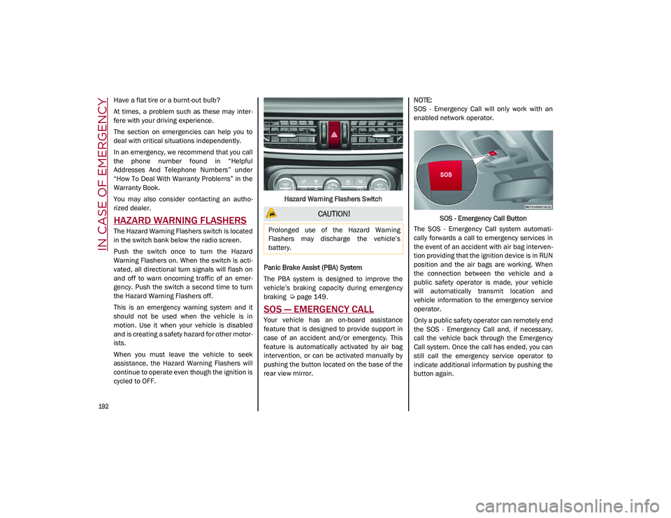
The Hazard Warning Flashers switch is located
in the switch bank below the radio screen.
Push the switch once to turn the Hazard
Warning Flashers on. When the switch is acti -
vated, all directional turn signals will flash on
and off to warn oncoming traffic of an emer -
gency. Push the switch a second time to turn
the Hazard Warning Flashers off.
This is an emergency warning system and it
should not be used when the vehicle is in
motion. Use it when your vehicle is disabled
and is creating a safety hazard for other motor -
ists.
When you must leave the vehicle to seek
assistance, the Hazard Warning Flashers will
continue to operate even though the ignition is
cycled to OFF. Hazard Warning Flashers Switch
Panic Brake Assist (PBA) System
The PBA system is designed to improve the
vehicle’s braking capacity during emergency
braking
Ú
page 149.
SOS — EMERGENCY CALL
Your vehicle has an on-board assistance
feature that is designed to provide support in
case of an accident and/or emergency. This
feature is automatically activated by air bag
intervention, or can be activated manually by
pushing the button located on the base of the
rear view mirror.
NOTE:
SOS - Emergency Call will only work with an
enabled network operator.
SOS - Emergency Call Button
The SOS - Emergency Call system automati -
cally forwards a call to emergency services in
the event of an accident with air bag interven -
tion providing that the ignition device is in RUN
position and the air bags are working. When
the connection between the vehicle and a
public safety operator is made, your vehicle
will automatically transmit location and
vehicle information to the emergency service
operator.
Only a public safety operator can remotely end
the SOS - Emergency Call and, if necessary,
call the vehicle back through the Emergency
Call system. Once the call has ended, you can
still call the emergency service operator to
indicate additional information by pushing the
button again.
CAUTION!
Prolonged use of the Hazard Warning
Flashers may discharge the vehicle’s
battery.
21_GU_OM_EN_USC_t.book Page 192
Page 196 of 280
IN CASE OF EMERGENCY
194
(Continued)
Even if the SOS - Emergency Call system is fully
functional, external or uncontrolled factors
may prevent or stop SOS - Emergency Call
operation. These include, but are not limited
to, the following factors:
The ignition is in OFF position.
The vehicle’s electrical systems are not
intact.
The SOS - Emergency Call system software
and/or hardware is damaged during a
vehicle collision.
There are network problems that could limit
or impair service operation (e.g., error by
operator, busy network, bad weather, etc.).
If the vehicle battery connection fails due to a
collision or accident, the system can support
an SOS - Emergency Call for a limited period of
time. If the battery is disconnected for service,
the system turns off. In this case, it will be
possible to make an SOS - Emergency Call only
when the battery is reconnected to the
vehicle’s electrical system.
System Requirements
Vehicle must have an operable 3G network
connection.
Vehicle must be powered with a properly
functioning electrical system.
The ignition must be in the RUN or ACC posi -
tion.
WARNING!
Never place anything on or near the
vehicle’s 3G and GPS aerials. You could
prevent 3G and GPS signal reception,
which can prevent your vehicle from
placing an emergency call. An operable
3G network connection and a GPS signal
is required for the SOS-Emergency Call
system to function properly.
Do not add any aftermarket electrical
equipment to the vehicle’s electrical
system. This may prevent your vehicle
from sending a signal to initiate an emer -
gency call. To avoid interference that can
cause the SOS-Emergency Call system to
fail, never add aftermarket equipment
(e.g., two-way mobile radio, CB radio, data
recorder, etc.) to your vehicle’s electrical
system or modify the antennas on your
vehicle. IF YOUR VEHICLE AND SYSTEM
LOSES BATTERY POWER FOR ANY
REASON (INCLUDING DURING OR AFTER
AN ACCIDENT) THE SOS FEATURES, APPS
AND SERVICES AMONG OTHERS WILL
NOT OPERATE.
The Occupant Restraint Controller (ORC)
turns on the air bag warning light in the
instrument cluster if a malfunction in any
part of the air bag system is detected. If
the air bag warning light is illuminated, the
air bag system may not be working prop -
erly and the SOS-Emergency Call system
may not be able to send a signal to an
emergency service operator. If the air bag
warning light is illuminated, contact the
Service Network to have the air bag
system checked immediately.
Ignoring the LED on the SOS-Emergency
Call button could mean you will not have
emergency call services if needed. If the
LED on SOS-Emergency Call button is illu -
minated red, contact the Service Network
to have the emergency call system
checked immediately.
If anyone in the vehicle could be in danger
(e.g., fire or smoke is visible, dangerous
road conditions or location), do not wait
for voice contact from an emergency
service operator. All occupants should exit
the vehicle immediately and move to a
safe location.
Failure to perform scheduled mainte -
nance and regularly inspect your vehicle
may result in vehicle damage, accident or
injury.
WARNING! (Continued)
21_GU_OM_EN_USC_t.book Page 194
Page 219 of 280
217
Washer Fluid For Windshield/Headlights
The windshield and headlight (if equipped)
washer fluid reservoir is equipped with a tele-
scopic filler neck.
If the level is too low, remove reservoir cap and
lift the filler neck. Then, add the fluid
described
Ú
page 263. After filling the reser -
voir, lower the filler neck and install the reser -
voir cap until you hear it click.
NOTE:
The headlight washers are activated every 10
activations of the windshield washer.
note:
The headlight washing system will not work if
the liquid level is low (situation indicated by
the symbol on the instrument cluster display
Ú
page 69). The windshield washer will keep
working.
On vehicles equipped with headlight washers,
there is a reference notch on the dipstick:
ONLY the windshield/rear window washer
operates with the level below this reference.
Brake Fluid
Check that the fluid is at the maximum level. If
the fluid level in the tank is low, contact an
authorized dealer to have the system checked.
Automatic Transmission Activation System
Oil
The transmission control oil level should only
be checked at an authorized dealer.
Useful Advice For Extending The Life Of
Your Battery
To avoid draining your battery and make it last
longer, observe the following instructions:
When you park the vehicle, ensure that the
doors and liftgate are closed properly to
prevent any lights from remaining on inside
the passenger's compartment.
Do not keep accessories (e.g. radio, hazard
warning lights, etc.) switched on for a long
time when the engine is not running.
Before performing any operation on the
electrical system, disconnect the negative
battery cable.
If you wish to install electrical accessories
after purchasing the vehicle that require
permanent electrical supply (e.g. alarm, etc.),
or accessories which influence the electrical
supply requirements, contact an authorized
dealer, who’s qualified staff will evaluate the
overall electrical consumption.
NOTE:
After the battery is disconnected, the steering
must be initialized. The warning light on the
instrument cluster display switches on to indi
-
cate this. To carry out this procedure, simply
turn the steering wheel all the way from one
end to the other, and then turn it back to the
central position.Battery
The battery does not require the electrolyte to
be topped up with distilled water. A periodic
check carried out at an authorized dealer,
however, is necessary to check efficiency.
Follow the battery manufacturer's instructions
for maintenance.
CAUTION!
If the charge level remains under 50% for a
long time, the battery may be damaged by
sulfation, reducing its capacity and
efficiency during the vehicle start. The
battery is also more prone to the risk of
freezing (at temperatures as high as 14°F
(-10°C).
21_GU_OM_EN_USC_t.book Page 217