2021 ALFA ROMEO STELVIO tow
[x] Cancel search: towPage 207 of 280
205
(Continued)
MANUAL PARK RELEASE
See an authorized dealer to disengage the
manual park release lever.
TOWING A DISABLED VEHICLE
This section describes procedures for towing a
disabled vehicle using a commercial towing
service.
NOTE:
If your vehicle is equipped with a Anti-Lift
Protection system, you will need to disable the
system prior to towing by pushing the button
located on the overhead console
Ú
page 23.
The operators of the assistance vehicle must
be informed with regard to the vehicle's
minimum height from ground in order to avoid
contact between the ends of the bumpers with
the equipment of the breakdown truck.
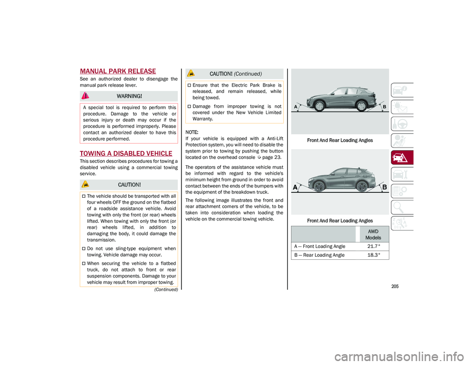
The following image illustrates the front and
rear attachment corners of the vehicle, to be
taken into consideration when loading the
vehicle on the commercial towing vehicle. Front And Rear Loading Angles
Front And Rear Loading Angles
WARNING!
A special tool is required to perform this
procedure. Damage to the vehicle or
serious injury or death may occur if the
procedure is performed improperly. Please
contact an authorized dealer to have this
procedure performed.
CAUTION!
The vehicle should be transported with all
four wheels OFF the ground on the flatbed
of a roadside assistance vehicle. Avoid
towing with only the front (or rear) wheels
lifted. When towing with only the front (or
rear) wheels lifted, in addition to
damaging the body, it could damage the
transmission.
Do not use sling-type equipment when
towing. Vehicle damage may occur.
When securing the vehicle to a flatbed
truck, do not attach to front or rear
suspension components. Damage to your
vehicle may result from improper towing.
Ensure that the Electric Park Brake is
released, and remain released, while
being towed.
Damage from improper towing is not
covered under the New Vehicle Limited
Warranty.
CAUTION! (Continued)
AWD
Models
A — Front Loading Angle 21.7°
B — Rear Loading Angle 18.3°
21_GU_OM_EN_USC_t.book Page 205
Page 208 of 280
IN CASE OF EMERGENCY
206
(Continued)
Four-Wheel Drive (AWD) Models
It is recommended to tow the vehicle with all
four wheels OFF the ground on the flatbed of a
commercial towing vehicle.
TOW EYES
If the vehicle has been in an accident or has
broken down, a tow eye is provided in the tools
container located inside the luggage compart-
ment for vehicle towing. Towing is meant only
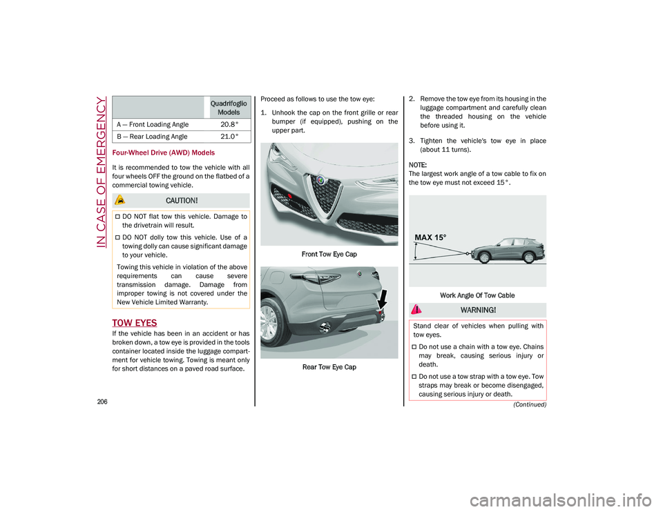
for short distances on a paved road surface. Proceed as follows to use the tow eye:
1. Unhook the cap on the front grille or rear
bumper (if equipped), pushing on the
upper part.
Front Tow Eye CapRear Tow Eye Cap 2. Remove the tow eye from its housing in the
luggage compartment and carefully clean
the threaded housing on the vehicle
before using it.
3. Tighten the vehicle's tow eye in place (about 11 turns).
NOTE:
The largest work angle of a tow cable to fix on
the tow eye must not exceed 15°.
Work Angle Of Tow Cable
Quadrifoglio Models
A — Front Loading Angle 20.8°
B — Rear Loading Angle 21.0°
CAUTION!
DO NOT flat tow this vehicle. Damage to
the drivetrain will result.
DO NOT dolly tow this vehicle. Use of a
towing dolly can cause significant damage
to your vehicle.
Towing this vehicle in violation of the above
requirements can cause severe
transmission damage. Damage from
improper towing is not covered under the
New Vehicle Limited Warranty.
WARNING!
Stand clear of vehicles when pulling with
tow eyes.
Do not use a chain with a tow eye. Chains
may break, causing serious injury or
death.
Do not use a tow strap with a tow eye. Tow
straps may break or become disengaged,
causing serious injury or death.
21_GU_OM_EN_USC_t.book Page 206
Page 209 of 280
207
ENHANCED ACCIDENT
RESPONSE SYSTEM (EARS)
This vehicle is equipped with an Enhanced
Accident Response System.
This feature is a communication network that
takes effect in the event of an impact
Ú
page 175.
EVENT DATA RECORDER (EDR)
This vehicle is equipped with an event data
recorder (EDR). The main purpose of an EDR is
to record data that will assist in understanding
how a vehicle’s systems performed under
certain crash or near crash-like situations,
such as an air bag deployment or hitting a road
obstacle
Ú
page 178.
Failure to follow proper tow eye usage may
cause components to break resulting in
serious injury or death.
CAUTION!
The tow eye must be used exclusively for
roadside assistance operations. Only use
the tow eye with an appropriate device in
accordance with the highway code (a rigid
bar or rope) to flat tow the vehicle for a
short distance to the nearest service loca -
tion.
Tow eyes MUST NOT be used to tow vehi -
cles off the road or where there are obsta -
cles.
In compliance with the above conditions,
towing with a tow eye must take place with
two vehicles (one towing, the other towed)
aligned as much as possible along the
same center line. Damage to your vehicle
may occur if these guidelines are not
followed.
When towing, only use a facility that can
tow vehicles with low ground clearances
as extensive damage can result by using a
standard tow truck platform.
WARNING! (Continued)
21_GU_OM_EN_USC_t.book Page 207
Page 215 of 280
213
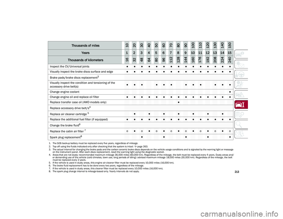
Inspect the CV/Universal joints●●●●●●●●●●●●●●●
Visually inspect the brake discs surface and edge
●●●●●●●●●●●●●●●
Brake pads/brake discs replacement
3
Visually
inspect the condition and tensioning of the
accessory drive belt(s)
●●●●●●●●●●●●
Change engine coolant
●
Change engine oil and replace oil filter
●●●●●●●●●●●●●●●
Replace transfer case oil (AWD models only)
●
Replace accessory drive belt/s4
Replace
air cleaner cartridge
5●●●●●●●
Replace the additional fuel filter (if equipped)●●●●●●●●●●●●●●●
Change the brake fluid
6
Replace
the cabin air filter
7 o●o●o●o●o●o●o●o
Spark plug replacement
8●●●●●
1. The SOS backup battery must be replaced every five years, regardless of mileage.
2. Top off using the fluids indicated only after checking that the system is intact
Ú
page 263.
3. The actual interval for changing the brake pads and the carbon ceramic brake discs depends on the vehicle usage conditions and is signaled by the warning light or message on the instrument panel. After each discs replacement, reset the warning light using the diagnostic socket.
4. Areas that are not dusty: recommended maximum mileage 36,000 miles (60,000 km). Regardless of the mileage, the belt must be replaced every 4 years. Dusty areas and/ or demanding use of the vehicle (cold climates, town use, long periods of idling): advised maximum mileage 18,000 miles (30,000 km). Regardless of the mileage, the belt must be replaced every 2 years.
5. If the vehicle is used in dusty areas, this engine air cleaner filter must be replaced every 10,000 miles (16,000 km).
6. The brake fluid replacement has to be done every two years, regardless of the mileage.
7. If the vehicle is used in dusty areas, this cleaner filter must be replaced every 10,000 miles (16,000 km). 8. The spark plug change interval is mileage-based only. Yearly intervals do not apply.
Thousands of miles102030405060708090100110120130140150
Years123456789101112131415
Thousands of kilometers163248648096112128144160176192208224240
21_GU_OM_EN_USC_t.book Page 213
Page 231 of 280
229
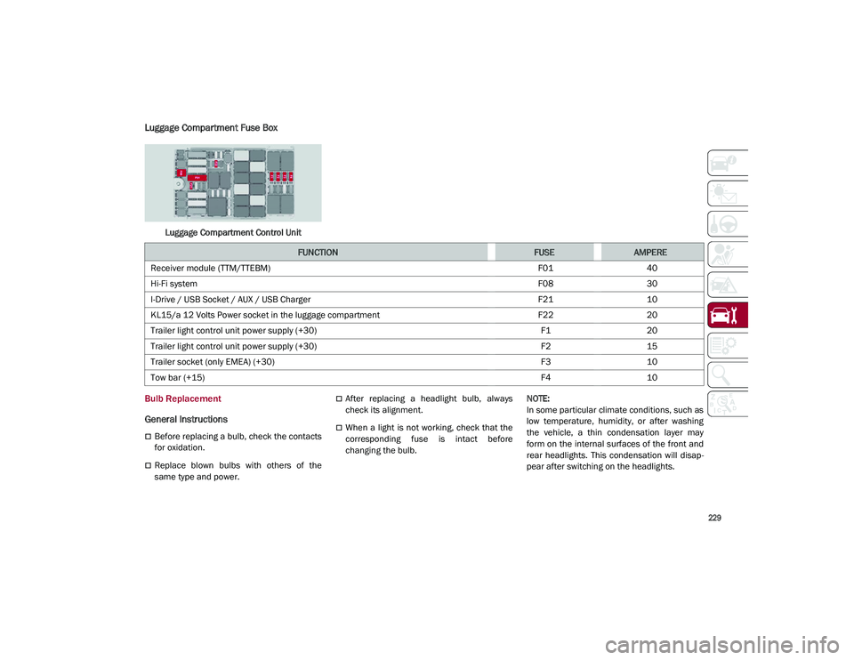
Luggage Compartment Fuse Box
Luggage Compartment Control Unit
Bulb Replacement
General Instructions
Before replacing a bulb, check the contacts
for oxidation.
Replace blown bulbs with others of the
same type and power.
After replacing a headlight bulb, always
check its alignment.
When a light is not working, check that the
corresponding fuse is intact before
changing the bulb.
NOTE:
In some particular climate conditions, such as
low temperature, humidity, or after washing
the vehicle, a thin condensation layer may
form on the internal surfaces of the front and
rear headlights. This condensation will disap
-
pear after switching on the headlights.
FUNCTIONFUSEAMPERE
Receiver module (TTM/TTEBM) F0140
Hi-Fi system F0830
I-Drive / USB Socket / AUX / USB Charger F2110
KL15/a 12 Volts Power socket in the luggage compartment F2220
Trailer light control unit power supply (+30) F120
Trailer light control unit power supply (+30) F215
Trailer socket (only EMEA) (+30) F310
Tow bar (+15) F410
21_GU_OM_EN_USC_t.book Page 229
Page 240 of 280
SERVICING AND MAINTENANCE
238
NOTE:
Under a maximum loaded vehicle condition,
gross axle weight ratings (GAWRs) for the front
and rear axles must not be exceeded. For
further information on GAWRs, vehicle
loading, and trailer towing
Ú
page 135.
To determine the maximum loading conditions
of your vehicle, locate the statement “The
combined weight of occupants and cargo
should never exceed XXX kg or XXX lbs” on the
Tire and Loading Information placard. The
combined weight of occupants, cargo/luggage
and trailer tongue weight (if applicable) should
never exceed the weight referenced here.
Steps For Determining Correct Load
Limit—
(1) Locate the statement “The
combined weight of occupants and
cargo should never exceed XXX kg or
XXX lbs.” on your vehicle's placard.
(2) Determine the combined weight of
the driver and passengers that will be
riding in your vehicle.
(3) Subtract the combined weight of the
driver and passengers from XXX kg or
XXX lbs. (4) The resulting figure equals the avail
-
able amount of cargo and luggage load
capacity. For example, if “XXX” amount
equals 1400 lbs. and there will be five
150 lb passengers in your vehicle, the
amount of available cargo and luggage
load capacity is 650 lbs. (1400-750
(5x150) = 650 lbs.).
(5) Determine the combined weight of
luggage and cargo being loaded on the
vehicle. That weight may not safely
exceed the available cargo and luggage
load capacity calculated in Step 4.
(6) If your vehicle will be towing a trailer,
load from your trailer will be transferred
to your vehicle. Consult this manual to
determine how this reduces the avail -
able cargo and luggage load capacity of
your vehicle.
Metric Example For Load Limit
For example, if “XXX” amount equals 635 kg
and there will be five 68 kg passengers in your
vehicle, the amount of available cargo and
luggage load capacity is 295 kg (635-340
(5x68) = 295 kg) as shown in step 4.
NOTE:
If your vehicle will be towing a trailer, load
from your trailer will be transferred to your
vehicle. The following table shows examples
on how to calculate total load, cargo/
luggage, and towing capacities of your
vehicle with varying seating configurations
and number and size of occupants. This
table is for illustration purposes only and
may not be accurate for the seating and
load carry capacity of your vehicle.
For the following example, the combined
weight of occupants and cargo should never
exceed 865 lbs (392 kg).
21_GU_OM_EN_USC_t.book Page 238
Page 245 of 280
243
Run Flat Tires — If Equipped
Run Flat tires allow you the capability to drive
50 miles (80 km) at 50 mph (80 km/h) after a
rapid loss of inflation pressure. This rapid loss
of inflation is referred to as the Run Flat mode.
A Run Flat mode occurs when the tire inflation
pressure is of/or below 14 psi (96 kPa). Once
a Run Flat tire reaches the run flat mode it has
limited driving capabilities and needs to be
replaced immediately. A Run Flat tire is not
repairable. When a run flat tire is changed
after driving with underinflated tire condition,
please replace the TPM sensor as it is not
designed to be reused when driven under run
flat mode 14 psi (96 kPa) condition.
NOTE:
TPM Sensor must be replaced after driving the
vehicle on a flat tire condition.
It is not recommended driving a vehicle loaded
at full capacity or to tow a trailer while a tire is
in the run flat mode.
For more information
Ú
page 161.
Tire Spinning
When stuck in mud, sand, snow, or ice condi -
tions, do not spin your vehicle's wheels above
30 mph (48 km/h) or for longer than 30 seconds
continuously without stopping.
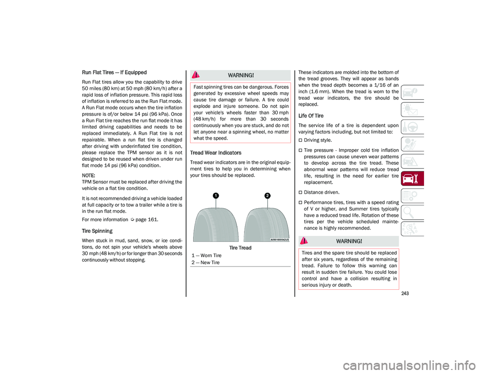
Tread Wear Indicators
Tread wear indicators are in the original equip -
ment tires to help you in determining when
your tires should be replaced.
Tire Tread These indicators are molded into the bottom of
the tread grooves. They will appear as bands
when the tread depth becomes a 1/16 of an
inch (1.6 mm). When the tread is worn to the
tread wear indicators, the tire should be
replaced.
Life Of Tire
The service life of a tire is dependent upon
varying factors including, but not limited to:
Driving style.
Tire pressure - Improper cold tire inflation
pressures can cause uneven wear patterns
to develop across the tire tread. These
abnormal wear patterns will reduce tread
life, resulting in the need for earlier tire
replacement.
Distance driven.
Performance tires, tires with a speed rating
of V or higher, and Summer tires typically
have a reduced tread life. Rotation of these
tires per the vehicle scheduled mainte
-
nance is highly recommended.
WARNING!
Fast spinning tires can be dangerous. Forces
generated by excessive wheel speeds may
cause tire damage or failure. A tire could
explode and injure someone. Do not spin
your vehicle's wheels faster than 30 mph
(48 km/h) for more than 30 seconds
continuously when you are stuck, and do not
let anyone near a spinning wheel, no matter
what the speed.
1 — Worn Tire
2 — New Tire
WARNING!
Tires and the spare tire should be replaced
after six years, regardless of the remaining
tread. Failure to follow this warning can
result in sudden tire failure. You could lose
control and have a collision resulting in
serious injury or death.
21_GU_OM_EN_USC_t.book Page 243
Page 261 of 280
259
Luggage Compartment Volume
Capacity (VDA standards)
Rear seats not folded
Vehicle unladen: 18.54 cubic feet (525 liters)
WEIGHTS
Weights (lbs)2.0L Engine AWD2.0L Engine RWD
Unladen weight (with all fluids, fuel tank filled to 90% and without optional equipment) 4,007
3,901
Payload including the driver
1
1. If special equipment is fitted (trailer towing equipment, etc.) the empty weight will increase and consequently the payload will decrease in relation to the maximum permitted loads.
992 992
Maximum permitted loads
2
2. Loads not to be exceeded. The user is responsible for arranging goods in the luggage compartment and/or on the load platform within the maximum permitted loads.
242 242
Front axle 2,4912,403
Rear axle 2,9762,932
Total 5,2475,115
Towable loads --
Braked trailer 3,000 lbs (1,360 kg)3,000 lbs (1,360 kg)
Unbraked trailer 1,000 lbs (454 kg)1,000 lbs (454 kg)
Maximum load on roof 165 lbs (75 kg)165 lbs (75 kg)
Maximum load on tow hitch (braked trailer) 300 lbs (136 kg)300 lbs (136 kg)
Weights (lbs)2.9L engine
Unladen weight (with all fluids, fuel tank filled to 90% and
without optional equipment) 4,313
Payload including the driver
1992
21_GU_OM_EN_USC_t.book Page 259