2021 ALFA ROMEO STELVIO sensor
[x] Cancel search: sensorPage 165 of 280
163
To reactivate the TPMS, replace all four wheel
and tire assemblies (road tires) with tires
equipped with TPMS sensors. Then, drive the
vehicle for up to 20 minutes above 15 mph
(24 km/h). The TPMS will chime, the TPMS
Warning Light will flash on and off for 75
seconds and then turn off. The instrument
cluster will display the “SERVICE TPM
SYSTEM” message and then display pressure
values in place of the dashes. On the next igni-
tion switch cycle the “SERVICE TPM SYSTEM”
message will no longer be displayed, as long
as no system fault exists.
NOTE:
The TPMS is not intended to replace normal
tire care and maintenance, or to provide
warning of a tire failure or condition.
The TPMS should not be used as a tire pres -
sure gauge while adjusting your tire pres -
sure.
Driving on a significantly underinflated tire
will cause the tire to overheat, and can lead
to tire failure. Underinflation also reduces
fuel efficiency and tire tread life, and may
affect the vehicle’s handling and stopping
ability.
The TPMS is not a substitute for proper tire
maintenance, and it is the driver’s responsi -
bility to maintain correct tire pressure using
an accurate tire pressure gauge, even if underinflation has not reached the level to
trigger illumination of the TPMS Warning
Light.
Seasonal temperature changes will affect
tire pressure, and the TPMS will monitor the
actual tire pressure in the tire
Ú
page 268.
OCCUPANT RESTRAINT
SYSTEMS
Some of the most important safety features in
your vehicle are the restraint systems:
Occupant Restraint Systems Features
Seat Belt Systems
Supplemental Restraint Systems (SRS) Air
Bags
Child Restraints
Some of the safety features described in this
section may be standard equipment on some
models, or may be optional equipment on
others. If you are not sure, ask an authorized
dealer.
Important Safety Precautions
Please pay close attention to the information
in this section. It tells you how to use your
restraint system properly, to keep you and
your passengers as safe as possible. Here are some simple steps you can take to
minimize the risk of harm from a deploying air
bag:
1. Children 12 years old and under should
always ride buckled up in the rear seat of
a vehicle with a rear seat.
2. A child who is not big enough to wear the vehicle seat belt properly must be secured
in the appropriate child restraint or
belt-positioning booster seat in a rear
seating position
Ú
page 178.
3. If a child from 2 to 12 years old (not in a rear-facing child restraint) must ride in the
front passenger seat, move the seat as far
back as possible and use the proper child
restraint
Ú
page 178.
4. Never allow children to slide the shoulder belt behind them or under their arm.
5. You should read the instructions provided with your child restraint to make sure that
you are using it properly.
6. All occupants should always wear their lap and shoulder belts properly.
7. The driver and front passenger seats should be moved back as far as practical
to allow the front air bags room to inflate.
8. Do not lean against the door or window. If your vehicle has side air bags, and deploy -
ment occurs, the side air bags will inflate
21_GU_OM_EN_USC_t.book Page 163
Page 171 of 280
169
Supplemental Restraint Systems (SRS)
Some of the safety features described in this
section may be standard equipment on some
models, or may be optional equipment on
others. If you are not sure, ask an authorized
dealer.
The air bag system must be ready to protect
you in a collision. The Occupant Restraint
Controller (ORC) monitors the internal circuits
and interconnecting wiring associated with the
electrical Air Bag System Components. Your
vehicle may be equipped with the following Air
Bag System Components:
Air Bag System Components
Occupant Restraint Controller (ORC)
Air Bag Warning Light
Steering Wheel and Column
Instrument Panel
Knee Impact Bolsters
Driver and Front Passenger Air Bags
Seat Belt Buckle Switch
Supplemental Side Air Bags
Supplemental Knee Air Bags
Front and Side Impact Sensors
Seat Belt Pretensioners
Seat Track Position Sensors
Air Bag Warning Light
The Occupant Restraint Controller
(ORC) monitors the readiness of the
electronic parts of the air bag system
whenever the ignition switch is in the
START or ON/RUN position. If the ignition
switch is in the OFF position or in the ACC posi -
tion, the air bag system is not on and the air
bags will not inflate.
The ORC contains a backup power supply
system that may deploy the air bag system
even if the battery loses power or it becomes
disconnected prior to deployment.
The ORC turns on the Air Bag Warning Light in
the instrument panel for approximately four to
eight seconds for a self-check when the igni -
tion switch is first in the ON/RUN position.
After the self-check, the Air Bag Warning Light
will turn off. If the ORC detects a malfunction
in any part of the system, it turns on the Air
Bag Warning Light, either momentarily or continuously. A single chime will sound to alert
you if the light comes on again after initial
startup.
The ORC also includes diagnostics that will illu
-
minate the instrument panel Air Bag Warning
Light if a malfunction is detected that could
affect the air bag system. The diagnostics also
record the nature of the malfunction. While
the air bag system is designed to be mainte -
nance free, if any of the following occurs, have
an authorized dealer service the air bag
system immediately.The Air Bag Warning Light does not come on
during the four to eight seconds when the
ignition switch is first in the ON/RUN posi -
tion.
The Air Bag Warning Light remains on after
the four to eight-second interval.
The Air Bag Warning Light comes on inter-
mittently or remains on while driving.
NOTE:
If the speedometer, tachometer, or any engine
related gauges are not working, the Occupant
Restraint Controller (ORC) may also be
disabled. In this condition the air bags may not
be ready to inflate for your protection. Have an
authorized dealer service the air bag system
immediately.
Do not use the Automatic Locking Mode to
restrain occupants who are wearing the
seat belt or children who are using booster
seats. The locked mode is only used to
install rear-facing or forward-facing child
restraints that have a harness for
restraining the child.
WARNING! (Continued)
21_GU_OM_EN_USC_t.book Page 169
Page 173 of 280
171
(Continued)
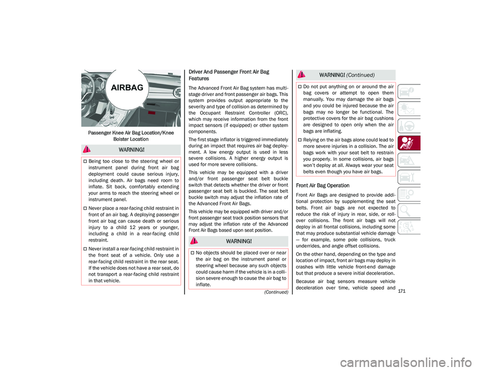
Passenger Knee Air Bag Location/Knee Bolster Location
Driver And Passenger Front Air Bag
Features
The Advanced Front Air Bag system has multi -
stage driver and front passenger air bags. This
system provides output appropriate to the
severity and type of collision as determined by
the Occupant Restraint Controller (ORC),
which may receive information from the front
impact sensors (if equipped) or other system
components.
The first stage inflator is triggered immediately
during an impact that requires air bag deploy -
ment. A low energy output is used in less
severe collisions. A higher energy output is
used for more severe collisions.
This vehicle may be equipped with a driver
and/or front passenger seat belt buckle
switch that detects whether the driver or front
passenger seat belt is buckled. The seat belt
buckle switch may adjust the inflation rate of
the Advanced Front Air Bags.
This vehicle may be equipped with driver and/or
front passenger seat track position sensors that
may adjust the inflation rate of the Advanced
Front Air Bags based upon seat position.
Front Air Bag Operation
Front Air Bags are designed to provide addi -
tional protection by supplementing the seat
belts. Front air bags are not expected to
reduce the risk of injury in rear, side, or roll -
over collisions. The front air bags will not
deploy in all frontal collisions, including some
that may produce substantial vehicle damage
— for example, some pole collisions, truck
underrides, and angle offset collisions.
On the other hand, depending on the type and
location of impact, front air bags may deploy in
crashes with little vehicle front-end damage
but that produce a severe initial deceleration.
Because air bag sensors measure vehicle
deceleration over time, vehicle speed and
WARNING!
Being too close to the steering wheel or
instrument panel during front air bag
deployment could cause serious injury,
including death. Air bags need room to
inflate. Sit back, comfortably extending
your arms to reach the steering wheel or
instrument panel.
Never place a rear-facing child restraint in
front of an air bag. A deploying passenger
front air bag can cause death or serious
injury to a child 12 years or younger,
including a child in a rear-facing child
restraint.
Never install a rear-facing child restraint in
the front seat of a vehicle. Only use a
rear-facing child restraint in the rear seat.
If the vehicle does not have a rear seat, do
not transport a rear-facing child restraint
in that vehicle.
WARNING!
No objects should be placed over or near
the air bag on the instrument panel or
steering wheel because any such objects
could cause harm if the vehicle is in a colli -
sion severe enough to cause the air bag to
inflate.
Do not put anything on or around the air
bag covers or attempt to open them
manually. You may damage the air bags
and you could be injured because the air
bags may no longer be functional. The
protective covers for the air bag cushions
are designed to open only when the air
bags are inflating.
Relying on the air bags alone could lead to
more severe injuries in a collision. The air
bags work with your seat belt to restrain
you properly. In some collisions, air bags
won’t deploy at all. Always wear your seat
belts even though you have air bags.
WARNING! (Continued)
21_GU_OM_EN_USC_t.book Page 171
Page 175 of 280
173
(Continued)
Supplemental Side Air Bag Inflatable Curtains
(SABICs)
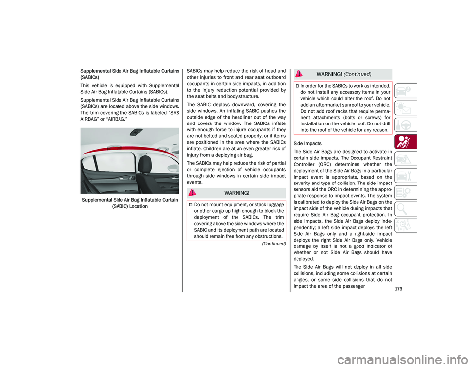
This vehicle is equipped with Supplemental
Side Air Bag Inflatable Curtains (SABICs).
Supplemental Side Air Bag Inflatable Curtains
(SABICs) are located above the side windows.
The trim covering the SABICs is labeled “SRS
AIRBAG” or “AIRBAG.”Supplemental Side Air Bag Inflatable Curtain (SABIC) Location SABICs may help reduce the risk of head and
other injuries to front and rear seat outboard
occupants in certain side impacts, in addition
to the injury reduction potential provided by
the seat belts and body structure.
The SABIC deploys downward, covering the
side windows. An inflating SABIC pushes the
outside edge of the headliner out of the way
and covers the window. The SABICs inflate
with enough force to injure occupants if they
are not belted and seated properly, or if items
are positioned in the area where the SABICs
inflate. Children are at an even greater risk of
injury from a deploying air bag.
The SABICs may help reduce the risk of partial
or complete ejection of vehicle occupants
through side windows in certain side impact
events.
Side Impacts
The Side Air Bags are designed to activate in
certain side impacts. The Occupant Restraint
Controller (ORC) determines whether the
deployment of the Side Air Bags in a particular
impact event is appropriate, based on the
severity and type of collision. The side impact
sensors aid the ORC in determining the appro
-
priate response to impact events. The system
is calibrated to deploy the Side Air Bags on the
impact side of the vehicle during impacts that
require Side Air Bag occupant protection. In
side impacts, the Side Air Bags deploy inde -
pendently; a left side impact deploys the left
Side Air Bags only and a right-side impact
deploys the right Side Air Bags only. Vehicle
damage by itself is not a good indicator of
whether or not Side Air Bags should have
deployed.
The Side Air Bags will not deploy in all side
collisions, including some collisions at certain
angles, or some side collisions that do not
impact the area of the passenger
WARNING!
Do not mount equipment, or stack luggage
or other cargo up high enough to block the
deployment of the SABICs. The trim
covering above the side windows where the
SABIC and its deployment path are located
should remain free from any obstructions.
In order for the SABICs to work as intended,
do not install any accessory items in your
vehicle which could alter the roof. Do not
add an aftermarket sunroof to your vehicle.
Do not add roof racks that require perma -
nent attachments (bolts or screws) for
installation on the vehicle roof. Do not drill
into the roof of the vehicle for any reason.
WARNING! (Continued)
21_GU_OM_EN_USC_t.book Page 173
Page 176 of 280
SAFETY
174
(Continued)
compartment. The Side Air Bags may deploy
during angled or offset frontal collisions where
the front air bags deploy.
Side Air Bags are a supplement to the seat belt
restraint system. Side Air Bags deploy in less
time than it takes to blink your eyes.
NOTE:
Air bag covers may not be obvious in the inte-
rior trim, but they will open during air bag
deployment.
Rollover Events
Side Air Bags and seat belt pretensioners are
designed to activate in certain rollover events.
The Occupant Restraint Controller (ORC)
determines whether deployment in a partic -
ular rollover event is appropriate, based on the
severity and type of collision. Vehicle damage
by itself is not a good indicator of whether or
not Side Air Bags and seat belt pretensioners
should have deployed.
The Side Air Bags and seat belt pretensioners
will not deploy in all rollover events. The roll -
over sensing system determines if a rollover
event may be in progress and whether deploy -
ment is appropriate. In the event the vehicle
experiences a rollover or near rollover event, and deployment is appropriate, the rollover
sensing system will deploy the side air bags
and seat belt pretensioners on both sides of
the vehicle.
The SABICs may help reduce the risk of partial
or complete ejection of vehicle occupants
through side windows in certain rollover or
side impact events.
Air Bag System Components
NOTE:
The Occupant Restraint Controller (ORC) moni
-
tors the internal circuits and interconnecting
wiring associated with electrical Air Bag
System Components listed below:
Occupant Restraint Controller (ORC)
Air Bag Warning Light
Steering Wheel and Column
Instrument Panel
Knee Impact Bolsters
Driver and Front Passenger Air Bags
Seat Belt Buckle Switch
Supplemental Side Air Bags
Supplemental Knee Air Bags
Front and Side Impact Sensors
Seat Belt Pretensioners
Seat Track Position Sensors
WARNING!
Occupants, including children, who are up
against or very close to Side Air Bags can
be seriously injured or killed. Occupants,
including children, should never lean on or
sleep against the door, side windows, or
area where the side air bags inflate, even
if they are in an infant or child restraint.
Seat belts (and child restraints where appro -
priate) are necessary for your protection in
all collisions. They also help keep you in
position, away from an inflating Side Air Bag.
To get the best protection from the Side Air
Bags, occupants must wear their seat belts
properly and sit upright with their backs
against the seats. Children must be properly
restrained in a child restraint or booster seat
that is appropriate for the size of the child.
WARNING!
Side Air Bags need room to inflate. Do not
lean against the door or window. Sit
upright in the center of the seat.
Being too close to the Side Air Bags during
deployment could cause you to be
severely injured or killed.
Relying on the Side Air Bags alone could
lead to more severe injuries in a collision.
The Side Air Bags work with your seat belt
to restrain you properly. In some colli -
sions, Side Air Bags won’t deploy at all.
Always wear your seat belt even though
you have Side Air Bags.
WARNING! (Continued)
21_GU_OM_EN_USC_t.book Page 174
Page 221 of 280
219
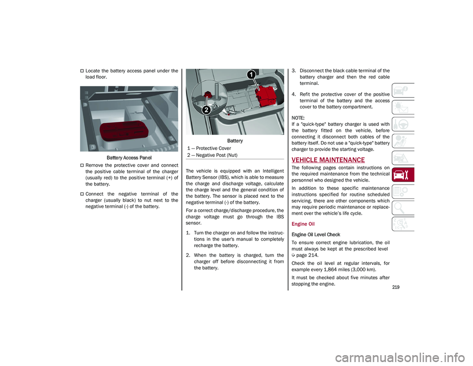
Locate the battery access panel under the
load floor.Battery Access Panel
Remove the protective cover and connect
the positive cable terminal of the charger
(usually red) to the positive terminal (+) of
the battery.
Connect the negative terminal of the
charger (usually black) to nut next to the
negative terminal (-) of the battery. Battery
The vehicle is equipped with an Intelligent
Battery Sensor (IBS), which is able to measure
the charge and discharge voltage, calculate
the charge level and the general condition of
the battery. The sensor is placed next to the
negative terminal (-) of the battery.
For a correct charge/discharge procedure, the
charge voltage must go through the IBS
sensor.
1. Turn the charger on and follow the instruc -
tions in the user's manual to completely
recharge the battery.
2. When the battery is charged, turn the charger off before disconnecting it from
the battery. 3. Disconnect the black cable terminal of the
battery charger and then the red cable
terminal.
4. Refit the protective cover of the positive terminal of the battery and the access
cover to the battery compartment.
NOTE:
If a "quick-type" battery charger is used with
the battery fitted on the vehicle, before
connecting it disconnect both cables of the
battery itself. Do not use a "quick-type" battery
charger to provide the starting voltage.
VEHICLE MAINTENANCE
The following pages contain instructions on
the required maintenance from the technical
personnel who designed the vehicle.
In addition to these specific maintenance
instructions specified for routine scheduled
servicing, there are other components which
may require periodic maintenance or replace -
ment over the vehicle’s life cycle.
Engine Oil
Engine Oil Level Check
To ensure correct engine lubrication, the oil
must always be kept at the prescribed level
Ú
page 214.
Check the oil level at regular intervals, for
example every 1,864 miles (3,000 km).
It must be checked about five minutes after
stopping the engine.
1 — Protective Cover
2 — Negative Post (Nut)
21_GU_OM_EN_USC_t.book Page 219
Page 244 of 280
SERVICING AND MAINTENANCE
242
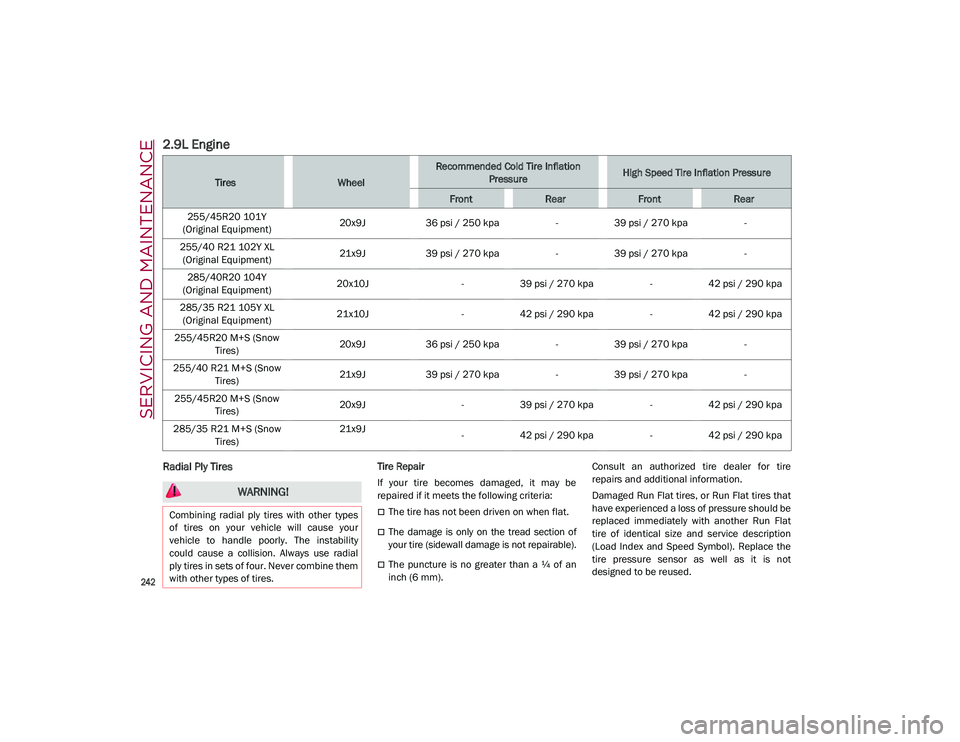
2.9L Engine
Radial Ply Tires Tire Repair
If your tire becomes damaged, it may be
repaired if it meets the following criteria:
The tire has not been driven on when flat.
The damage is only on the tread section of
your tire (sidewall damage is not repairable).
The puncture is no greater than a ¼ of an
inch (6 mm).Consult an authorized tire dealer for tire
repairs and additional information.
Damaged Run Flat tires, or Run Flat tires that
have experienced a loss of pressure should be
replaced immediately with another Run Flat
tire of identical size and service description
(Load Index and Speed Symbol). Replace the
tire pressure sensor as well as it is not
designed to be reused.
TiresWheel
Recommended Cold Tire Inflation
PressureHigh Speed Tire Inflation Pressure
FrontRearFrontRear
255/45R20 101Y
(Original Equipment) 20x9J
36 psi / 250 kpa -39 psi / 270 kpa -
255/40 R21 102Y XL (Original Equipment) 21x9J
39 psi / 270 kpa -39 psi / 270 kpa -
285/40R20 104Y
(Original Equipment) 20x10J
-39 psi / 270 kpa -42 psi / 290 kpa
285/35 R21 105Y XL (Original Equipment) 21x10J
-42 psi / 290 kpa -42 psi / 290 kpa
255/45R20 M+S (Snow Tires) 20x9J
36 psi / 250 kpa -39 psi / 270 kpa -
255/40 R21 M+S (Snow Tires) 21x9J
39 psi / 270 kpa -39 psi / 270 kpa -
255/45R20 M+S (Snow Tires) 20x9J
-39 psi / 270 kpa -42 psi / 290 kpa
285/35 R21 M+S (Snow Tires) 21x9J
-42 psi / 290 kpa -42 psi / 290 kpa
WARNING!
Combining radial ply tires with other types
of tires on your vehicle will cause your
vehicle to handle poorly. The instability
could cause a collision. Always use radial
ply tires in sets of four. Never combine them
with other types of tires.
21_GU_OM_EN_USC_t.book Page 242
Page 245 of 280
243
Run Flat Tires — If Equipped
Run Flat tires allow you the capability to drive
50 miles (80 km) at 50 mph (80 km/h) after a
rapid loss of inflation pressure. This rapid loss
of inflation is referred to as the Run Flat mode.
A Run Flat mode occurs when the tire inflation
pressure is of/or below 14 psi (96 kPa). Once
a Run Flat tire reaches the run flat mode it has
limited driving capabilities and needs to be
replaced immediately. A Run Flat tire is not
repairable. When a run flat tire is changed
after driving with underinflated tire condition,
please replace the TPM sensor as it is not
designed to be reused when driven under run
flat mode 14 psi (96 kPa) condition.
NOTE:
TPM Sensor must be replaced after driving the
vehicle on a flat tire condition.
It is not recommended driving a vehicle loaded
at full capacity or to tow a trailer while a tire is
in the run flat mode.
For more information
Ú
page 161.
Tire Spinning
When stuck in mud, sand, snow, or ice condi -
tions, do not spin your vehicle's wheels above
30 mph (48 km/h) or for longer than 30 seconds
continuously without stopping.
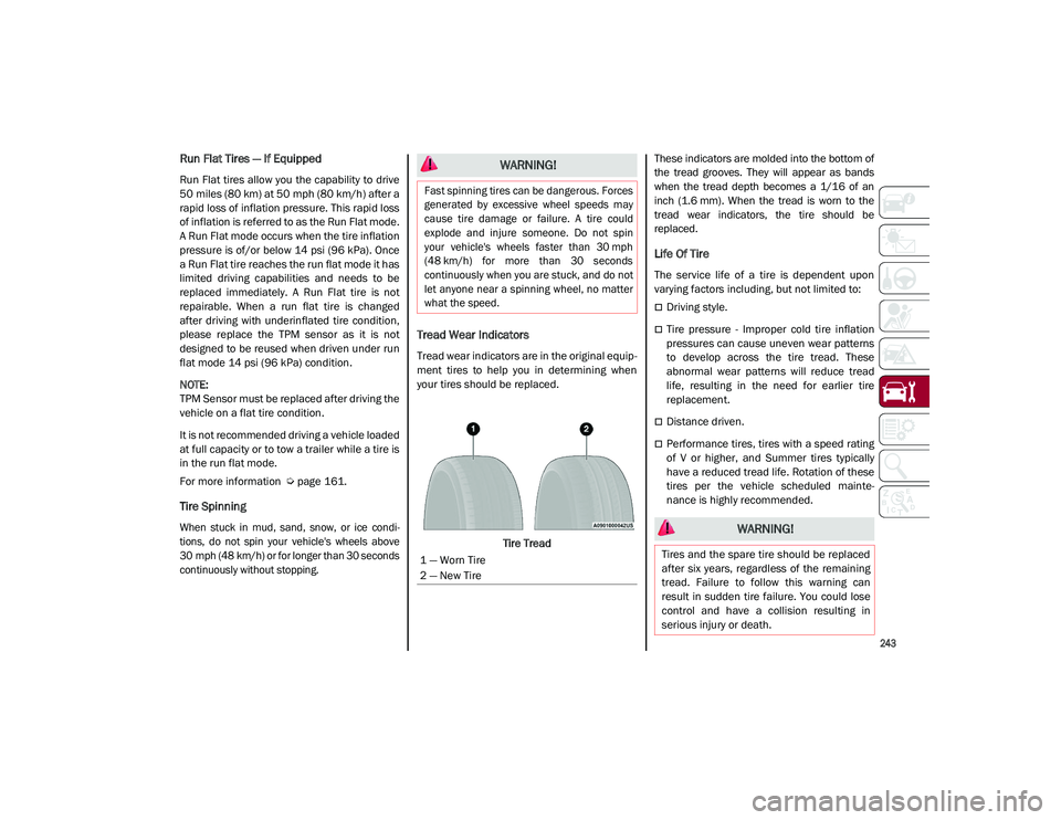
Tread Wear Indicators
Tread wear indicators are in the original equip -
ment tires to help you in determining when
your tires should be replaced.
Tire Tread These indicators are molded into the bottom of
the tread grooves. They will appear as bands
when the tread depth becomes a 1/16 of an
inch (1.6 mm). When the tread is worn to the
tread wear indicators, the tire should be
replaced.
Life Of Tire
The service life of a tire is dependent upon
varying factors including, but not limited to:
Driving style.
Tire pressure - Improper cold tire inflation
pressures can cause uneven wear patterns
to develop across the tire tread. These
abnormal wear patterns will reduce tread
life, resulting in the need for earlier tire
replacement.
Distance driven.
Performance tires, tires with a speed rating
of V or higher, and Summer tires typically
have a reduced tread life. Rotation of these
tires per the vehicle scheduled mainte
-
nance is highly recommended.
WARNING!
Fast spinning tires can be dangerous. Forces
generated by excessive wheel speeds may
cause tire damage or failure. A tire could
explode and injure someone. Do not spin
your vehicle's wheels faster than 30 mph
(48 km/h) for more than 30 seconds
continuously when you are stuck, and do not
let anyone near a spinning wheel, no matter
what the speed.
1 — Worn Tire
2 — New Tire
WARNING!
Tires and the spare tire should be replaced
after six years, regardless of the remaining
tread. Failure to follow this warning can
result in sudden tire failure. You could lose
control and have a collision resulting in
serious injury or death.
21_GU_OM_EN_USC_t.book Page 243