2021 ALFA ROMEO STELVIO lights
[x] Cancel search: lightsPage 56 of 280
GETTING TO KNOW YOUR VEHICLE
54
the flow of air. The air vanes of the center
outlets and outboard outlets can be moved up
and down or side to side to regulate airflow
direction. There is a shut off wheel located
below the air vanes to shut off or adjust the
amount of airflow from these outlets.
Bi-Level Mode
Air comes from the instrument panel
outlets and floor outlets. A slight
amount of air is directed through the
defrost and side window demister
outlets.
NOTE:
Bi-Level mode is designed under comfort
conditions to provide cooler air out of the
panel outlets and warmer air from the floor
outlets.
Floor Mode
Air comes from the floor outlets. A
slight amount of air is directed
through the defrost and side window
demister outlets. This setting heats
the passenger compartment the quickest.
Mix Mode
Air is directed through the floor,
defrost, and side window demister
outlets. This setting works best in
cold or snowy conditions that require
extra heat to the windshield. This setting is
good for maintaining comfort while reducing
moisture on the windshield.
Front Defrost And Panel Mode
Air flow is distributed between the
windshield demisting/defrosting
vents and side/central dashboard
vents. This setting allows air to flow
to the windshield on sunny days.
Front Defrost And Bi-Level Mode
Air flow is distributed to all vents.
Switching The Climate Control System On/
Off
To Turn Off The Climate Control System
Rotate the Air Speed Adjustment Knob
completely counterclockwise to turn off the
Climate Control system.
With the air conditioner is off:
Air recirculation is on
The A/C compressor is off
The fan is off
The heated rear window can be activated/
deactivated
NOTE:
The Climate Control system stores the previ -
ously set temperatures and resumes opera -
tion when any button on the system is pushed. To Turn On The Climate Control System
To switch the Climate Control system on in
automatic mode, push the AUTO button.
Operating Mode
The Climate Control system can be activated
in different ways. It is recommended to use the
automatic function. Push the AUTO button and
set the desired temperatures.
The automatic system adjusts the tempera
-
ture, quantity, and distribution of air intro -
duced into the passenger compartment. It
also controls air recirculation and the activa -
tion of the air conditioner.
At any time during automatic operation, you
can change the temperature, activate or deac -
tivate the Rear Defrost, activate SYNC, acti -
vate or deactivate the air conditioner, and
activate or deactivate air recirculation. The
system will automatically adjust to the new
settings.
Climate Control Display Settings
The Climate Control settings are visible on the
radio screen.
The display on the radio system is a pop up
window, which is activated by pushing the
buttons or turning the knobs on the Climate
Control system. The indicator lights located on
the buttons and knobs indicate that the
selected feature is on/off. If no operation is
performed for a predetermined time, the
pop-up will close on the display.
21_GU_OM_EN_USC_t.book Page 54
Page 64 of 280
GETTING TO KNOW YOUR VEHICLE
62
Closing The Hood
To close, lower the hood to approximately
16 inches (40 cm) from the engine compart-
ment then let it drop. Make sure that the hood
is completely closed and fully latched.
NOTE:
Since the hood is equipped with a double
locking system, one for each side, you must
check that it is closed on each side.
POWER LIFTGATE
Unlocking of the liftgate is electrically oper -
ated and is deactivated when the vehicle is in
motion.
If anything obstructs the power liftgate while it
is closing or opening, the liftgate will automat -
ically reverse to the closed or open position,
provided it meets sufficient resistance.
Opening
The liftgate may be released in several ways:
Pressing the liftgate release button on the
key fob twice within five seconds
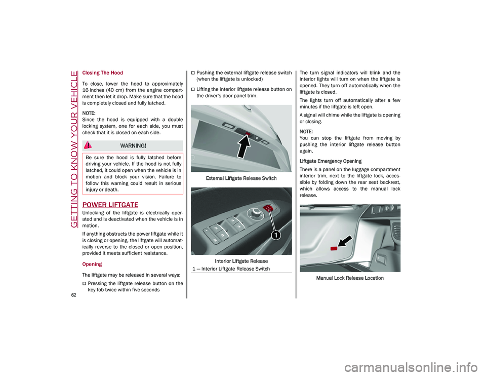
Pushing the external liftgate release switch
(when the liftgate is unlocked)
Lifting the interior liftgate release button on
the driver’s door panel trim.
External Liftgate Release Switch
Interior Liftgate Release The turn signal indicators will blink and the
interior lights will turn on when the liftgate is
opened. They turn off automatically when the
liftgate is closed.
The lights turn off automatically after a few
minutes if the liftgate is left open.
A signal will chime while the liftgate is opening
or closing.
NOTE:
You can stop the liftgate from moving by
pushing the interior liftgate release button
again.
Liftgate Emergency Opening
There is a panel on the luggage compartment
interior trim, next to the liftgate lock, acces
-
sible by folding down the rear seat backrest,
which allows access to the manual lock
release.
Manual Lock Release Location
WARNING!
Be sure the hood is fully latched before
driving your vehicle. If the hood is not fully
latched, it could open when the vehicle is in
motion and block your vision. Failure to
follow this warning could result in serious
injury or death.
1 — Interior Liftgate Release Switch
21_GU_OM_EN_USC_t.book Page 62
Page 71 of 280
69
3. Instrument Cluster Display•The instrument cluster display features
a driver interactive display
Ú
page 69.
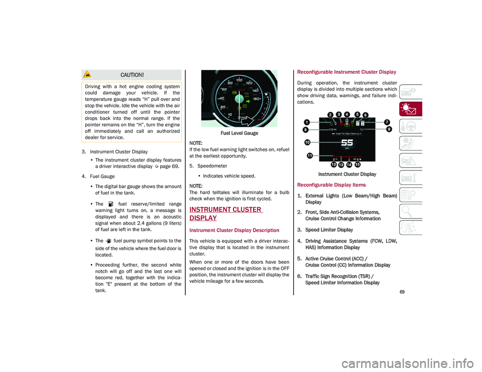
4. Fuel Gauge •The digital bar gauge shows the amount
of fuel in the tank.
• The fuel reserve/limited range
warning light turns on, a message is
displayed and there is an acoustic
signal when about 2.4 gallons (9 liters)
of fuel are left in the tank.
• The fuel pump symbol points to the
side of the vehicle where the fuel door is
located.
• P
roceeding further, the second white
notch will go off and the last one will become red, together with the indica-
tion "E" present at the bottom of the
tank. Fuel
Level Gauge
NOTE:
If the low fuel warning light switches on, refuel
at the earliest opportunity.
5. Speedometer •Indicates vehicle speed.
NOTE:
The hard telltales will illuminate for a bulb
check when the ignition is first cycled.
INSTRUMENT CLUSTER
DISPLAY
Instrument Cluster Display Description
This vehicle is equipped with a driver interac -
tive display that is located in the instrument
cluster.
When one or more of the doors have been
opened or closed and the ignition is in the OFF
position, the instrument cluster will display the
vehicle mileage for a few seconds.
Reconfigurable Instrument Cluster Display
During operation, the instrument cluster
display is divided into multiple sections which
show driving data, warnings, and failure indi -
cations.
Instrument Cluster Display
Reconfigurable Display Items
1. External Lights (Low Beam/High Beam)Display
2. Front, Side Anti-Collision Systems, Cruise Control Change Information
3. Speed Limiter Display
4. Driving Assistance Systems (FCW, LDW, HAS) Information Display
5. Active Cruise Control (ACC) / Cruise Control (CC) Information Display
6. Traffic Sign Recognition (TSR) / Speed Limiter Information Display
CAUTION!
Driving with a hot engine cooling system
could damage your vehicle. If the
temperature gauge reads “H” pull over and
stop the vehicle. Idle the vehicle with the air
conditioner turned off until the pointer
drops back into the normal range. If the
pointer remains on the “H”, turn the engine
off immediately and call an authorized
dealer for service.
21_GU_OM_EN_USC_t.book Page 69
Page 73 of 280
71
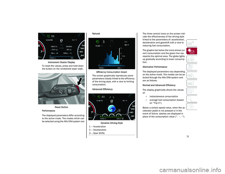
Instrument Cluster Display
To reset the values, press and hold down
the button on the windshield wiper stalk.
Reset Button
Performance
The displayed parameters differ according
to the active mode. The modes which can
be selected using the Alfa DNA system are: Natural
Efficiency Consumption Graph
The screen graphically reproduces some
parameters closely linked to the efficiency
of the driving style, with a view to limiting
consumption.
Advanced Efficiency
Dynamic Driving Style The three central icons on the screen indi
-
cate the effectiveness of the driving style
linked to the parameters of: acceleration,
deceleration and gearshift with a view to
reducing fuel consumption.
The graphic bar below the icons shows cur -
rent consumption and the green line rep -
resents the optimal area. The globe lights
up gradually according to lower consump -
tion.
Alternative Performance
The displayed parameters vary depending
on the active mode. The modes can be se -
lected through the Alfa DNA system and
are as follows:
Normal and Advanced Efficiency
The display graphically shows the values
of:
○ instantaneous consumption
○ average fuel consumption (based on “Trip A”);
Below a certain speed value, when the ac -
celerator pedal is not pressed or in the
event of failure, dashes are displayed in
place of the consumption value ("– –. –").
1 — Acceleration
2 — Deceleration
3 — Gear Shifts
21_GU_OM_EN_USC_t.book Page 71
Page 76 of 280
GETTING TO KNOW YOUR INSTRUMENT PANEL
74
(Continued)
To access and the change the setting, turn and
push the Rotary Pad or press the desired
setting on the touchscreen.
WARNING LIGHTS AND
MESSAGES ON THE
INSTRUMENT PANEL
The following pages consist of warning lights
and messages.
NOTE:
The warning light turns on together with a
dedicated message and/or chime when
applicable. These indications are precau-
tionary and as such must not be considered
as exhaustive and/or alternative to the
information contained in the Owner’s
Manual, which you are advised to read care -
fully in all cases. Always refer to the informa -
tion in this section in the event of a failure
indication.
The failure indicators appearing on the
display are divided into two categories: very
serious and less serious faults. Serious
faults are indicated by a repeated and
prolonged warning cycle. Less serious faults
are indicated by a warning cycle with a
shorter duration. You can stop the warning
cycle in both cases by pushing the button
located on the windshield wiper stalk. The
instrument panel warning light will stay on
until the cause of the failure is eliminated.
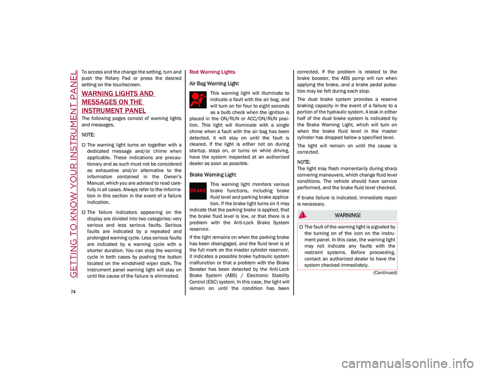
Red Warning Lights
Air Bag Warning Light
This warning light will illuminate to
indicate a fault with the air bag, and
will turn on for four to eight seconds
as a bulb check when the ignition is
placed in the ON/RUN or ACC/ON/RUN posi -
tion. This light will illuminate with a single
chime when a fault with the air bag has been
detected, it will stay on until the fault is
cleared. If the light is either not on during
startup, stays on, or turns on while driving,
have the system inspected at an authorized
dealer as soon as possible.
Brake Warning Light
This warning light monitors various
brake functions, including brake
fluid level and parking brake applica -
tion. If the brake light turns on it may
indicate that the parking brake is applied, that
the brake fluid level is low, or that there is a
problem with the Anti-Lock Brake System
reservoir.
If the light remains on when the parking brake
has been disengaged, and the fluid level is at
the full mark on the master cylinder reservoir,
it indicates a possible brake hydraulic system
malfunction or that a problem with the Brake
Booster has been detected by the Anti-Lock
Brake System (ABS) / Electronic Stability
Control (ESC) system. In this case, the light will
remain on until the condition has been corrected. If the problem is related to the
brake booster, the ABS pump will run when
applying the brake, and a brake pedal pulsa
-
tion may be felt during each stop.
The dual brake system provides a reserve
braking capacity in the event of a failure to a
portion of the hydraulic system. A leak in either
half of the dual brake system is indicated by
the Brake Warning Light, which will turn on
when the brake fluid level in the master
cylinder has dropped below a specified level.
The light will remain on until the cause is
corrected.
NOTE:
The light may flash momentarily during sharp
cornering maneuvers, which change fluid level
conditions. The vehicle should have service
performed, and the brake fluid level checked.
If brake failure is indicated, immediate repair
is necessary.
WARNING!
The fault of the warning light is signaled by
the turning on of the icon on the instru -
ment panel. In this case, the warning light
may not indicate any faults with the
restraint systems. Before proceeding,
contact an authorized dealer to have the
system checked immediately.
21_GU_OM_EN_USC_t.book Page 74
Page 77 of 280
75
Vehicles equipped with the Anti-Lock Brake
System (ABS) are also equipped with Elec-
tronic Brake Force Distribution (EBD). In the
event of an EBD failure, the Brake Warning
Light will turn on along with the ABS Light.
Immediate repair to the ABS system is
required.
Operation of the Brake Warning Light can be
checked by turning the ignition switch from the
OFF position to the ON/RUN position. The light
should illuminate for approximately two
seconds. The light should then turn off unless
the parking brake is applied or a brake fault is
detected. If the light does not illuminate, have
the light inspected by an authorized dealer.
The light also will turn on when the parking
brake is applied with the ignition switch in the
ON/RUN position.
NOTE:
This light shows only that the parking brake is
applied. It does not show the degree of brake
application.
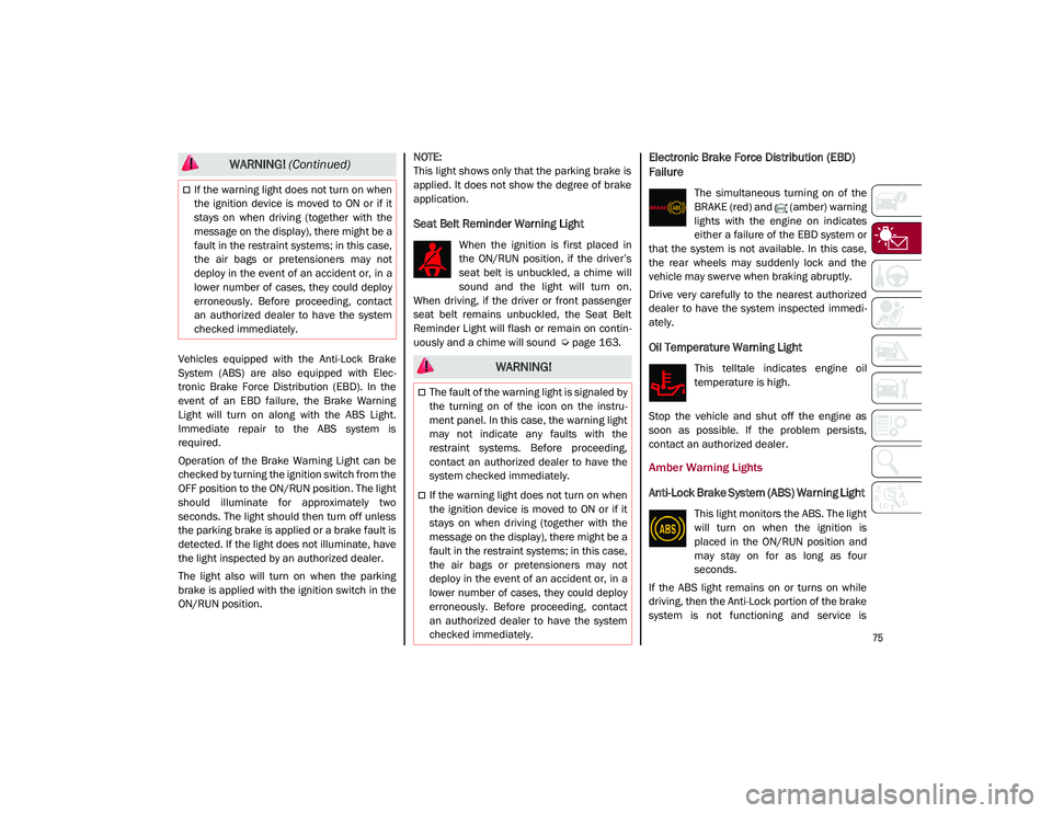
Seat Belt Reminder Warning Light
When the ignition is first placed in
the ON/RUN position, if the driver’s
seat belt is unbuckled, a chime will
sound and the light will turn on.
When driving, if the driver or front passenger
seat belt remains unbuckled, the Seat Belt
Reminder Light will flash or remain on contin -
uously and a chime will sound
Ú
page 163.
Electronic Brake Force Distribution (EBD)
Failure
The simultaneous turning on of the
BRAKE (red) and (amber) warning
lights with the engine on indicates
either a failure of the EBD system or
that the system is not available. In this case,
the rear wheels may suddenly lock and the
vehicle may swerve when braking abruptly.
Drive very carefully to the nearest authorized
dealer to have the system inspected immedi -
ately.
Oil Temperature Warning Light
This telltale indicates engine oil
temperature is high.
Stop the vehicle and shut off the engine as
soon as possible. If the problem persists,
contact an authorized dealer.
Amber Warning Lights
Anti-Lock Brake System (ABS) Warning Light
This light monitors the ABS. The light
will turn on when the ignition is
placed in the ON/RUN position and
may stay on for as long as four
seconds.
If the ABS light remains on or turns on while
driving, then the Anti-Lock portion of the brake
system is not functioning and service is
If the warning light does not turn on when
the ignition device is moved to ON or if it
stays on when driving (together with the
message on the display), there might be a
fault in the restraint systems; in this case,
the air bags or pretensioners may not
deploy in the event of an accident or, in a
lower number of cases, they could deploy
erroneously. Before proceeding, contact
an authorized dealer to have the system
checked immediately.
WARNING! (Continued)
WARNING!
The fault of the warning light is signaled by
the turning on of the icon on the instru -
ment panel. In this case, the warning light
may not indicate any faults with the
restraint systems. Before proceeding,
contact an authorized dealer to have the
system checked immediately.
If the warning light does not turn on when
the ignition device is moved to ON or if it
stays on when driving (together with the
message on the display), there might be a
fault in the restraint systems; in this case,
the air bags or pretensioners may not
deploy in the event of an accident or, in a
lower number of cases, they could deploy
erroneously. Before proceeding, contact
an authorized dealer to have the system
checked immediately.
21_GU_OM_EN_USC_t.book Page 75
Page 79 of 280
77
also reduces fuel efficiency and tire tread life,
and may affect the vehicle’s handling and
stopping ability.
Please note that the TPMS is not a substitute
for proper tire maintenance, and it is the
driver’s responsibility to maintain correct tire
pressure, even if under inflation has not
reached the level to trigger illumination of the
TPMS low tire pressure telltale.
Your vehicle has also been equipped with a
TPMS malfunction indicator to indicate when
the system is not operating properly. The
TPMS malfunction indicator is combined with
the low tire pressure telltale. When the system
detects a malfunction, the telltale will flash for
approximately one minute and then remain
continuously illuminated. This sequence will
continue upon subsequent vehicle start-ups
as long as the malfunction exists. When the
malfunction indicator is illuminated, the
system may not be able to detect or signal low
tire pressure as intended. TPMS malfunctions
may occur for a variety of reasons, including
the installation of replacement or alternate
tires or wheels on the vehicle that prevent the
TPMS from functioning properly. Always check
the TPMS malfunction telltale after replacing
one or more tires or wheels on your vehicle to
ensure that the replacement or alternate tires
and wheels allow the TPMS to continue to
function properly.
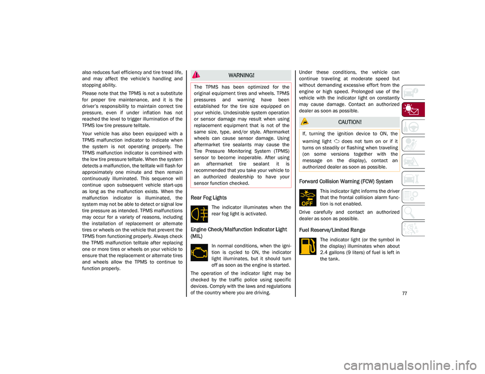
Rear Fog Lights
The indicator illuminates when the
rear fog light is activated.
Engine Check/Malfunction Indicator Light
(MIL)
In normal conditions, when the igni-
tion is cycled to ON, the indicator
light illuminates, but it should turn
off as soon as the engine is started.
The operation of the indicator light may be
checked by the traffic police using specific
devices. Comply with the laws and regulations
of the country where you are driving. Under these conditions, the vehicle can
continue traveling at moderate speed but
without demanding excessive effort from the
engine or high speed. Prolonged use of the
vehicle with the indicator light on constantly
may cause damage. Contact an authorized
dealer as soon as possible.
Forward Collision Warning (FCW) System
This indicator light informs the driver
that the frontal collision alarm func
-
tion is not enabled.
Drive carefully and contact an authorized
dealer as soon as possible.
Fuel Reserve/Limited Range
The indicator light (or the symbol in
the display) illuminates when about
2.4 gallons (9 liters) of fuel is left in
the tank.
WARNING!
The TPMS has been optimized for the
original equipment tires and wheels. TPMS
pressures and warning have been
established for the tire size equipped on
your vehicle. Undesirable system operation
or sensor damage may result when using
replacement equipment that is not of the
same size, type, and/or style. Aftermarket
wheels can cause sensor damage. Using
aftermarket tire sealants may cause the
Tire Pressure Monitoring System (TPMS)
sensor to become inoperable. After using
an aftermarket tire sealant it is
recommended that you take your vehicle to
an authorized dealership to have your
sensor function checked.
CAUTION!
If, turning the ignition device to ON, the
warning light does not turn on or if it
turns on steadily or flashing when traveling
(on some versions together with the
message on the display), contact an
authorized dealer as soon as possible.
21_GU_OM_EN_USC_t.book Page 77
Page 80 of 280
GETTING TO KNOW YOUR INSTRUMENT PANEL
78
Green Indicator Lights
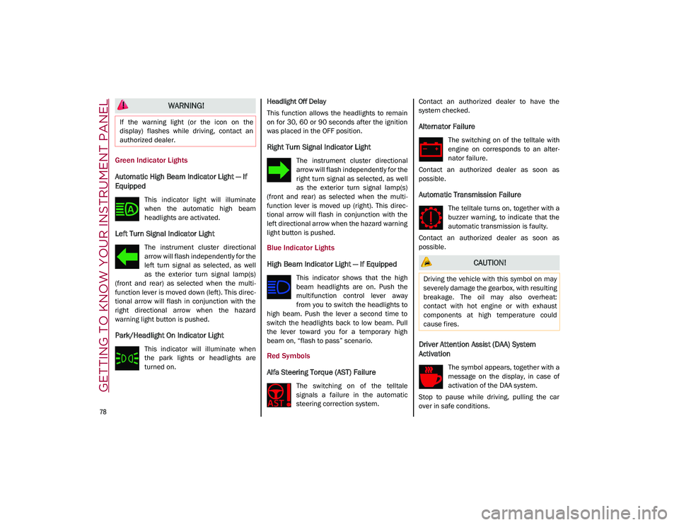
Automatic High Beam Indicator Light — If
Equipped
This indicator light will illuminate
when the automatic high beam
headlights are activated.
Left Turn Signal Indicator Light
The instrument cluster directional
arrow will flash independently for the
left turn signal as selected, as well
as the exterior turn signal lamp(s)
(front and rear) as selected when the multi -
function lever is moved down (left). This direc -
tional arrow will flash in conjunction with the
right directional arrow when the hazard
warning light button is pushed.
Park/Headlight On Indicator Light
This indicator will illuminate when
the park lights or headlights are
turned on. Headlight Off Delay
This function allows the headlights to remain
on for 30, 60 or 90 seconds after the ignition
was placed in the OFF position.
Right Turn Signal Indicator Light
The instrument cluster directional
arrow will flash independently for the
right turn signal as selected, as well
as the exterior turn signal lamp(s)
(front and rear) as selected when the multi -
function lever is moved up (right). This direc -
tional arrow will flash in conjunction with the
left directional arrow when the hazard warning
light button is pushed.
Blue Indicator Lights
High Beam Indicator Light — If Equipped
This indicator shows that the high
beam headlights are on. Push the
multifunction control lever away
from you to switch the headlights to
high beam. Push the lever a second time to
switch the headlights back to low beam. Pull
the lever toward you for a temporary high
beam on, “flash to pass” scenario.
Red Symbols
Alfa Steering Torque (AST) Failure
The switching on of the telltale
signals a failure in the automatic
steering correction system. Contact an authorized dealer to have the
system checked.
Alternator Failure
The switching on of the telltale with
engine on corresponds to an alter
-
nator failure.
Contact an authorized dealer as soon as
possible.
Automatic Transmission Failure
The telltale turns on, together with a
buzzer warning, to indicate that the
automatic transmission is faulty.
Contact an authorized dealer as soon as
possible.
Driver Attention Assist (DAA) System
Activation
The symbol appears, together with a
message on the display, in case of
activation of the DAA system.
Stop to pause while driving, pulling the car
over in safe conditions.
WARNING!
If the warning light (or the icon on the
display) flashes while driving, contact an
authorized dealer.
CAUTION!
Driving the vehicle with this symbol on may
severely damage the gearbox, with resulting
breakage. The oil may also overheat:
contact with hot engine or with exhaust
components at high temperature could
cause fires.
21_GU_OM_EN_USC_t.book Page 78